



A client recently brought us an urgent project requiring precision internal threads in heat-treated mold steel exceeding HRC60. Initial test parts passed inspection cleanly, but as production scaled, thread tolerances began drifting. Go/No-Go gauges bound inconsistently, minor burrs emerged along the crests, and cutting edges chipped prematurely. The client suspected poor tool quality, but a deep review of holder runout, pre-hole diameters, and programmed paths revealed the true root cause: the dynamics of the thread milling process needed a complete overhaul.
This scenario is common in precision machine shops. Most machinists know that thread milling uses helical interpolation rather than the direct axial drive of a tap. However, when cutting ultra-hard steels like HRC62 or HRC65, a standard helical path is not enough. Tool deflection, instantaneous radial engagement, and cutter-workpiece contact arcs dictate dimensional stability. At this hardness level, minor machining forces quickly multiply into severe pitch errors and premature tool failure.
At its mechanical core, thread milling relies on simultaneous multi-axis CNC interpolation rather than simple rotary displacement. The cutter executes a circular motion in the X-Y plane while synchronizing precise axial feed along the Z-axis to match the thread pitch. In standard carbon steels, slight cutter push-off often goes unnoticed. In hardened mold steel, extreme cutting resistance immediately exposes uneven chip loads, making tool rigidity and precise helical entry paths non-negotiable.
Consequently, cutting parameters for thread milling hardened steel cannot be selected from generic tool catalog charts. Variables like hole depth, thread pitch, and machine rigidity radically shift tool performance. An excessive radial depth of cut creates catastrophic load spikes that snap solid carbide teeth. Conversely, rubbing from overly light feeds work-hardens the surface instantly. Floor adjustments must prioritize balanced radial step-overs and consistent chip thickness over aggressive cycle times.
This balance highlights why thread milling outperforms tapping in difficult-to-machine alloys. Taps trap high torque inside the hole, turning a broken tool into a scrapped workpiece. In contrast, a thread mill operates with radial clearance, enabling safe chip evacuation, lower spindle load, and manageable tool wear. For blind holes in high-hardness steel, this clearance provides the process security that rigid tapping simply cannot match.
Mastering this process begins by shifting focus away from generic speeds and feeds. Instead, machinists must understand how tool engagement geometry transforms a blank hole into a true-to-gage thread. Evaluating radial depth, cutter diameter ratios, and enter-arc motions creates a stable, repeatable process that holds tight tolerances even in materials above HRC60.
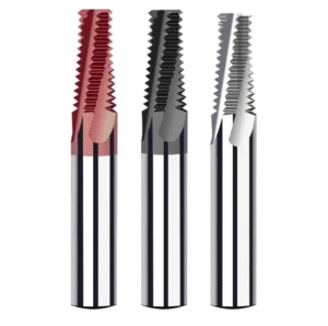
What is Thread Milling? Basic Principles of the Thread Milling Process
When evaluating process reliability on the shop floor, we look past tooling catalogs and examine the live cut. In a recent job threading blind holes in HRC62 mold steel, the first parts passed inspection, but pitch diameter drifted shortly after. The root cause was not tool failure, but an inaccurate kinematic setup. At its foundation, thread milling generates internal or external profiles by coordinating tool rotation with synchronized multi-axis CNC interpolation.
Before dialing in cutting speeds and feeds on hardened stock, machinists must master this kinetic relationship. The machine drives the spindle while interpolating the tool center along a circular path, shifting axially by exactly one pitch per revolution. Unlike conventional slot milling, thread milling high-hardness alloys leaves zero room for tracking errors. Minor path deviations instantly cause pitch errors, surface chatter, and chipped cutting edges.
How Does Thread Milling Create Threads Through Helical Motion?
Machinists often underestimate how dynamic helical interpolation is in hardened materials. Inside a blind hole, the cutter does not simply sweep around the perimeter. It combines continuous circular interpolation with steady Z-axis travel. In HRC60 to HRC65 steels, tool runout and arc radii directly affect the final form. An aggressive radial cut spikes lateral tool pressure, while an overly light cut rubs and work-hardens the part.
Helical motion governs the three-dimensional geometry of every cut. The circular path sets the pitch diameter, while simultaneous axial travel generates the precise thread lead. In thread milling hardened steel, this path must remain completely smooth. Abrupt direction changes or jerky feed transitions shock solid carbide flutes, destroying thread flank accuracy and tool life.
Basic Steps of the Thread Milling Process
A dependable setup always begins with meticulous pre-machining checks. We first verify the drilled pre-hole diameter and effective depth, then select a cutter diameter that leaves adequate chip clearance. Tool holder runout must stay under 0.0002 inches (5 microns) to prevent tooth overloading. In thread milling, rigid tool holding and verified dry runs prevent catastrophic cutter breaks in hard workpieces.
Once cutting begins, we monitor entry roll-in, helical progression, and tangential exit motion. After the initial pass, inspect the threads immediately using calibrated Go/No-Go plug gauges. If dimensions sit out of tolerance, adjust CNC tool radius compensation rather than altering raw geometry. This disciplined, step-by-step thread milling process ensures repeatable tolerances across production runs.
How Does the Thread Milling Toolpath Control Thread Formation?
We often see setups where tooling and machines check out fine, yet thread tolerances still drift. The problem almost always traces back to poor thread milling toolpath programming. Thread form generation is extremely sensitive to tool-center-point compensation. Any calculation error between the programmed arc radius, tool diameter, and major thread diameter directly distorts the flank angle.
Tool entry and exit strategies require equal precision. Never plunge straight into the cut; always program a smooth tangential roll-in arc to ease radial cutting forces onto the tool flutes. For hard steels, a stable thread milling toolpath balances chip load and limits radial deflection across multi-pass cuts. This programmed consistency delivers true-to-gage threads that satisfy the most stringent quality inspections.

How Does the Thread Milling Toolpath Achieve Threading?
Thread tolerance issues often stem from poor toolpath trajectory rather than bad tooling. In a project milling deep blind holes in HRC62 mold steel, the cutter generated flank scuffing and taper errors. The tooling was correct, but the tool-center trajectory failed to manage cutting pressure during circular interpolation. When machining ultra-hard alloys, the tool cannot simply trace a loop; the profile requires a smooth, coordinated spatial progression.
Before tweaking spindle speeds or table feeds, evaluate the core motion phases: roll-in arc, helical circle, pitch-synchronized Z-travel, and tangential exit. This diagnostic approach quickly reveals whether dimensional scrap is caused by premature insert wear, incorrect cutter compensation, or severe load spikes. Mastering the programmed thread milling toolpath is critical to maintaining process stability in hardened materials.
Helical Interpolation and the Thread Milling Toolpath
Helical interpolation coordinates circular X-Y motion with continuous Z-axis travel. As the cutter sweeps the bore diameter, it feeds axially by exactly one pitch per revolution. In rigid machining setups, the relationship between cutter diameter, pre-hole bore, and interpolation radius must be calculated accurately. Any mismatch between programmed geometry and machine kinematics distorts the pitch diameter and flank angle.
For workpieces exceeding HRC60, tool engagement must remain perfectly uniform. Abrupt plunge paths or erratic radius transitions produce violent force spikes on solid carbide flutes. A well-optimized thread milling toolpath maintains constant radial engagement and steady axial advance. This fluid spatial motion eliminates chatter marks and protects delicate cutting teeth from micro-chipping.
How Radial Infeed and Axial Feed Form the Thread Profile
Radial infeed governs chip thickness, while axial feed controls lead generation and pitch accuracy. To prevent cutter deflection in hardened steels, the tool must step over radially across multiple passes before reaching final depth. Oversized radial passes rapidly overload flutes, whereas rubbing passes cause severe work-hardening, friction, and thermal stress on the cutting edge.
During an HRC62 mold machining run, we eliminated tooth breakage by dividing the radial depth of cut into balanced roughing passes and one spring pass. Adjusting radial step-over balances cutting forces far better than simply backing off spindle speed. In thread milling hardened steel, radial engagement and axial timing must work together to maintain flank finish and tool life.
The Relationship Between Thread Pitch, Thread Depth, and Tool Motion
Thread pitch and depth establish the exact three-dimensional boundary for the cutter. Pitch defines the Z-travel required per 360-degree rotation, while depth determines total radial wall penetration. In blind holes, programming must account for hole-bottom clearance, chip clearance space, and safe radial retraction points before driving the tool clear.
When cutting steels from HRC62 to HRC65, never jump straight into production without verification. Perform a test cut and check gauge fit, flank finish, and tooth wear under a toolmaker’s microscope. If pitch diameter drifts, recheck tool radius offsets, radial pass distribution, and bore diameter. Matching thread milling kinematics directly to thread geometry ensures repeatable, high-precision results across difficult jobs.
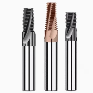
How Do Thread Milling Parameters Affect the Machining Process?
Machining parameters are never static numbers copied straight from a tooling catalog. On a recent job cutting internal threads in HRC62 die steel, changing to a longer holder triggered sudden chatter and scuffed thread flanks under previously successful settings. System rigidity and dynamic cutting forces had shifted. Dialing in thread milling parameters requires evaluating workpiece hardness, tool overhang, machine taper rigidity, and cutter diameter as an integrated system.
When cutting hard metals, parameter tuning is a delicate balancing act. Spindle speed controls thermal load at the cutting edge, feed rate dictates instantaneous tooth pressure, and radial engagement sets tool deflection. During live test cuts, listen for high-frequency squeal, watch the chip color, and inspect edge wear under magnification. Making incremental adjustments quickly establishes a reliable operating window in materials from HRC62 to HRC65.
Thread Milling Parameters: Cutting Speed and Spindle Speed
Surface footage must be calculated based on carbide substrate grade, workpiece hardness, and effective cutting diameter. Pushing cutting speed too high in high-hardness steel generates extreme friction, accelerating flank wear and micro-cracking the coating. Conversely, dropping RPM too low increases cutting pressure per tooth, risking edge fracture. Always establish surface speed first, then derive rotational spindle speed.
When thread milling alloys harder than HRC60, rapid edge breakdown usually points to thermal shock or excessive surface footage. Before backing off speeds, inspect tool runout, holder balance, and air-blast pressure used for chip evacuation. Cutting speed cannot be evaluated alone; it directly influences tool temperature and wear resistance. Balance your spindle speed with a rigid setup to prevent premature carbide degradation.
How Feed Rate and Feed per Tooth Affect Thread Milling
On the shop floor, table feed rate should always be derived from the programmed chip load per tooth. The number of flutes, spindle RPM, and internal arc compensation dictate the actual feed rate at the tool center. In hardened steel, an excessive feed per tooth chips fragile carbide edges. However, an overly light feed rubs the material, causing work-hardening and rapid flank wear.
Controlling chip load is vital when running multi-flute tools or threading small bores. For HRC62 to HRC65 materials, calculate internal circular feed carefully to prevent over-engaging the cutter flutes. Never spike feed rates simply to shave seconds off cycle times. Setting a consistent, calculated feed per tooth protects cutter teeth and keeps pitch diameters uniform part after part.
Controlling Cutting Load via Radial Engagement and Axial Depth
Radial engagement dictates the tool-workpiece contact arc, directly influencing cutting pressure and tool deflection. Taking heavy radial passes in hardened mold steel spikes lateral loads, creating chatter, pitch taper, and broken tools. Light, multi-pass roughing cuts maintain a stable contact arc, reducing vibration while preserving thread accuracy in deep cavities.
In deep-hole threading or HRC65 applications, excessive tool stick-out amplifies cutting forces. Distribute the total depth of cut across two to four balanced radial passes, finishing with a 0.001-inch spring pass to clean up tool push-off. Optimizing radial step-over alongside programmed thread milling parameters ensures exceptional flank finish, precise gauge fit, and dependable tool life.
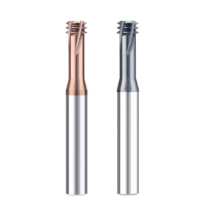
How Does Thread Milling in Hardened Steel Work?
Transitioning from soft pre-heat-treat steels to fully hardened tool steel exposes every weakness in a machining setup. In a past project milling threads into SKD11 heat-treated to HRC65, standard practices led to severe flank burrs and micro-chipping within three holes. Rather than blaming the cutter, we evaluated how radial engagement, cutter reach, and cutting load transfer behaved under extreme shear stress.
Successful thread milling in hardened steel requires isolating and balancing cutting forces. Ultra-hard alloys magnify minor vibrations and heat spikes that standard steels easily absorb. When tackling steels between HRC62 and HRC65, pairing a rigid tool holder with balanced radial depths of cut prevents tooth overloading, edge chipping, and dimensional drift.
The Cutting Mechanism of Thread Milling in Hardened Steel
Hardened alloys resist plastic deformation, causing extreme cutting forces to concentrate along a narrow contact arc. A solid carbide thread mill removes material incrementally through synchronized circular and axial motion. Because high-hardness alloys generate immense shear pressure, excessive radial step-over instantly spikes side loads, creating cutter deflection and taper errors inside the hole.
Chip control is equally vital to process stability. Recutting hard chips inside a blind hole scratches thread flanks and chips cutting edges. In thread milling hardened steel, apply a high-pressure air blast rather than flood coolant to evacuate chips cleanly and prevent thermal shock. Always evaluate chip color, acoustic pitch, and tool wear to confirm the cutting edge remains stable.
Cutting Characteristics of HRC62–HRC65 Hardened Steel
At HRC62 to HRC65, the usable machining window narrows significantly. High cutting resistance transfers vibration straight into the tool shank, amplifying runout and tool holder deflection. In heat-treated steels like SKD11, localized core hardness variations can also trigger unpredictable cutting load spikes, requiring conservative radial passes to prevent tool fracture.
Never select cutting parameters based on hardness alone. Bore depth, thread diameter, pitch, and cutter overhang dictate actual tool stability. Threading a shallow M4 hole behaves entirely differently from interpolating a deep cavity. Maintaining smooth toolpath kinematics and consistent tooth engagement ensures reliable thread quality in high-hardness tool steels.
Handling Cutting Loads in High-Hardness Materials with HRC65 Thread Mills
A dedicated HRC65 thread mill requires more than just an advanced AlTiN or TiSiN coating. The substrate must balance micro-grain hardness with edge toughness, supported by an optimized core diameter and negative rake geometry. In deep mold cavities, excessive tool stick-out easily induces harmonic chatter, ruining thread flank finish regardless of tool grade.
Protect the cutter teeth by dividing the total depth of cut into multiple light radial passes, followed by a zero-stock spring pass. Keep tool overhang as short as possible and lock runout under 0.0002 inches. When deploying an HRC65 thread mill, balancing radial stock removal against rigid machine kinematics delivers consistent thread accuracy, repeatable tool life, and zero broken tools.
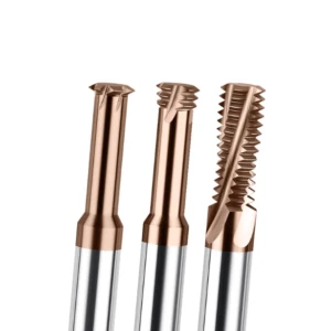
How Do Carbide Thread Mills Affect the Thread Milling Process?
Selecting the right tool for hard machining requires more than checking whether a cutter is labeled solid carbide. On a previous project tapping into mold cavities above HRC60, standard cutters dulled immediately, leaving scratched flanks and out-of-spec pitch diameters after three holes. Upgrading to a harder carbide grade alone failed to resolve the issue. The real solution required balancing substrate toughness, edge prep, cutter geometry, and live radial cutting pressures.
When cutting heat-treated tool steels, evaluate the cutting tool as an integrated mechanical system. The tungsten carbide substrate provides the structural core to resist lateral deflection, while flute geometry and thin-film coatings dictate chip flow and thermal defense. In the HRC62 to HRC65 bracket, machinists must balance wear resistance against fracture toughness. Selecting specialized carbide thread mills ensures the cutting edges survive interrupted cuts without chipping.
Carbide Substrates and Cutting Edges
The carbide substrate must withstand severe mechanical shock while maintaining a razor-sharp cutting wedge. In high-hardness alloys, the tool demands exceptional hardness to resist abrasive flank wear, combined with sufficient toughness for interrupted milling cycles. An overly hard, brittle sub-micron substrate fractures easily under slight machine chatter. Conversely, a tougher grade without adequate hot hardness deforms plastically under high cutting temperatures.
On the shop floor, inspecting the cutting edge under magnification reveals whether failure stems from abrasive wear or micro-fracture. When milling SKD11 dies, uniform flank wear indicates balanced parameters, whereas chipped cutting teeth point to severe runout or cutter deflection. High-performance solid carbide thread mills rely on reinforced edge hones that protect delicate crests from micro-chipping while keeping cutting forces manageable.
How Carbide Thread Mill Geometry Affects Thread Milling
Tool geometry directly controls cutting resistance, tooth engagement, and chip evacuation dynamics. In hard metal applications, multi-flute configurations distribute cutting forces across more teeth, reducing individual chip loads and stabilizing circular interpolation. Meanwhile, a thicker core web enhances tool rigidity to prevent taper errors, while optimized flute gullets ensure fine, hardened chips do not pack tightly inside blind holes.
Overhang length must be matched strictly to the required thread depth. Choosing a tool with excessive reach drastically lowers dynamic rigidity, inducing harmonic vibration that ruins surface finish even on premium machine centers. When selecting carbide thread mill geometry, balance flute core diameter, helix angle, and functional reach against the bore dimensions to maintain maximum stiffness throughout the helical path.
Coatings, Edge Strength, and Thread Milling of Hardened Steel
Advanced PVD coatings serve as a vital thermal barrier, but they cannot compensate for poor toolpath kinematics or spindle runout. Multi-layer coatings like AlTiN or TiSiN retain micro-hardness at temperatures exceeding 900°C, preventing thermal cracking during dry machining. However, an elite coating applied over a weak edge prep will still peel or chip under excessive radial step-overs.
When evaluating thread milling hardened steel, always look at coating adhesion and edge prep together. If thread finish degrades rapidly after a few parts, inspect the setup for thermal shock, dry air-blast volume, and toolholder runout under 0.0002 inches. Combining high-temperature PVD coatings with negative edge reinforcement gives carbide thread mills the heat and wear resistance needed to deliver repeatable, high-precision threads.
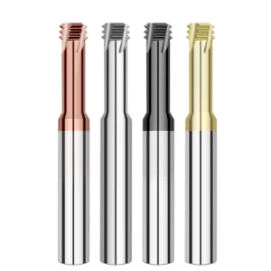
Thread Milling vs Tapping: What Are the Differences in Machining Principles?
Machinists often default to tapping because it is fast, familiar, and economical for standard steels. However, when cutting mold components heat-treated past HRC60, tapping frequently leads to tool binding, torn crests, and broken tools embedded in expensive cavities. We recently audited an aerospace job struggling with tap failure in hardened tool steel; switching the operation to thread milling restored dimensional control and eliminated catastrophic scrap.
Choosing between thread milling vs tapping is never about declaring a universal winner, but rather identifying the wider machining window. High-volume runs in soft aluminum strongly favor rigid tapping. Conversely, hardened alloys, deep blind holes, and tight pitch tolerances demand the process control of helical milling. Machinists must balance cycle times against the catastrophic costs of digging a snapped tap out of a finished core.
Tool Motion in Thread Milling vs Tapping
The core distinction between these methods lies in cutting kinematics. Tapping forces a full-profile tool straight down the hole axis in a 1:1 synchronized rotational feed, engaging every tooth simultaneously. In contrast, thread milling uses multi-axis CNC helical interpolation, moving a smaller-diameter tool around the bore perimeter while ramping axially along the pitch lead.
This kinematic difference drastically alters chip formation and clearance in blind holes. A tap wedges chips tightly into the flutes as it reaches the bottom of the bore. A thread mill operates with generous radial clearance, letting compressed air flush chips freely upward. This programmed toolpath flexibility also lets operators machine right down to the hole bottom without requiring deep tap relief.
Cutting Loads and Tool Breakage Risks: Thread Milling vs Tapping
In an HRC62 die cavity, extreme shear resistance creates massive torsional friction along the entire body of a tap. If chip evacuation stalls or the leading edge chips, the tap snaps instantly, often ruining an expensive, semi-finished workpiece. Because taps fill the bore diameter completely, extracting broken carbide remnants requires costly EDM burning or causes total part scrap.
In contrast, thread milling vs tapping for hardened steel offers far greater process security. Thread mills maintain a tool diameter substantially smaller than the hole, reducing cutting forces to a single point of tangential contact. If a thread mill chips, the tool does not wedge inside the part; operators simply replace the cutter, adjust wear offsets, and re-run the hole without scrapping the workpiece.
When Should You Choose Thread Milling Over Tapping?
Tapping remains the gold standard for high-speed production in unhardened carbon steels, brass, and structural aluminum. However, when machining HRC62 to HRC65 tool steels, exotic superalloys, or thin-walled components, thread milling is the superior solution. It eliminates spindle strain, accommodates single-point pitch adjustments via CNC offsets, and cuts multiple thread diameters using the same tool pitch profile.
Furthermore, thread mills allow machinists to fine-tune thread tolerance classes with simple tool radius compensation rather than buying specialized oversize taps. For expensive mold tooling, complex prototypes, and hard-milling operations, selecting thread milling over tapping shifts the focus from raw cycle time to risk mitigation, dimensional precision, and total process reliability.
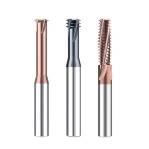
How to Control Thread Tolerance in Thread Milling?
Dimensional drift often catches machinists off guard during mid-run production. In a mold project cutting threads in HRC60 tool steel, the initial part passed inspection cleanly, but Go/No-Go plug gauges began binding after several pieces. The solid carbide cutter showed no visible chipping, yet pitch diameter had migrated out of tolerance. Root-cause analysis revealed that tool deflection and minor flute wear were shifting the effective cutting trajectory under load.
Achieving tight thread tolerance in thread milling requires managing tool deflection, spindle runout, and cutting forces simultaneously. In hard alloys from HRC62 to HRC65, consistent repeatability matters far more than passing a single first-piece inspection. Machinists must monitor effective tool radius, tool overhang, and machine repeatability together to hold Class 2B or 3B tolerances reliably across an entire production shift.
How the Thread Milling Toolpath Affects Thread Tolerance
The toolpath trajectory directly dictates thread pitch diameter and crest form. When interpolating internal threads, any discrepancy in tool center offset, lead-in arc radius, or bore diameter calculation immediately distorts the flank angle. Even slight path irregularities or sudden quadrant transitions create localized dwell marks that cause No-Go gauges to fail prematurely.
To hold tight thread tolerance, program a continuous tangential roll-in and roll-out arc rather than a direct linear plunge. This prevents shock loads that deflect the tool off its programmed center line. In deep bores or hardened materials, verifying toolpath continuity and maintaining a steady helical motion ensures the cutter generates a uniform, true-to-gage thread form from top to bottom.
Thread Milling Parameters and Thread Dimensional Accuracy
Cutting data directly influences cutting pressure, tool push-off, and final pitch diameter. When machining hardened materials, excessive chip loads or heavy radial step-overs cause the cutter shank to deflect away from the hole wall, cutting an undersized or tapered thread. This elastic deflection is often mistaken for incorrect tool sizing or inaccurate machine coordinates.
Rather than altering tool diameter offsets immediately, first inspect your thread milling parameters. Dividing the radial cut into two balanced roughing passes and a light spring pass relieves cutting pressure and eliminates tool push-off. Stabilizing cutting forces before tweaking offsets produces predictable dimensions, superior flank finish, and repeatable thread accuracy in high-hardness alloys.
Controlling Thread Tolerance via Tool Compensation
CNC tool radius compensation is designed for micro-adjusting pitch diameter, not masking an unstable machining setup. If a tool holder has excessive runout or the cutter is worn out, adjusting wear offsets only provides a temporary fix. True dimensional stability requires confirming mechanical rigidity and spindle accuracy before dialing in offset values on the control.
When running HRC65 steels, wear progresses gradually along the tool crests. Track pitch diameter growth across consecutive parts, and apply incremental tool compensation adjustments in small, traceable steps of 0.0002 to 0.0005 inches. Controlling thread tolerance in thread milling with measured offsets prevents over-cutting and keeps precision internal threads perfectly centered within specification.
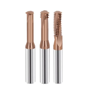
The Actual Machining Process for HRC65 Thread Mills
Machining ultra-hard tool steels requires far more than brute cutting force; it demands long-term process stability. When threading HRC62 to HRC65 mold inserts, we inspect material condition, hole size, and cutter overhang before generating the toolpath. In hardened tool steels like SKD11, bulk hardness is only one factor. Spindle taper rigidity, shrink-fit holder balance, and part clamping stiffness dictate final thread quality.
If you are running an HRC65 thread mill, examine your overall setup rather than pushing cycle times immediately. Premature tool wear usually stems from harmonic chatter or unbalanced radial loads rather than material hardness alone. Run test cuts to dial in a secure operating window, refining speeds, feeds, and radial depths based on gauge engagement and edge wear.
Which Hardened Steels Are Suitable for HRC65 Thread Mills?
A tool rated for high hardness should not be selected by Rockwell numbers alone. Mold steels like SKD11, D2, and powdered metallurgy grades generate severe shear resistance and localized heat. Microstructural variations, core hardness, and surface oxidation alter cutting dynamics significantly. Always evaluate the specific alloy, heat-treat condition, and bore geometry before cutting.
When choosing an HRC65 thread mill, verify the effective flute length and shank reach against your hole depth. Deep blind holes and small diameters require thick core webs and short overhangs to prevent deflection. For rigid, shallow threads, you can push parameters toward cycle efficiency. Matching tool geometry to hole depth delivers repeatable, chip-free threads in ultra-hard alloys.
How Should Thread Milling Parameters Be Set for HRC65 Thread Mills?
Dialing in cutting data requires coordinating speeds, feeds, and dynamic toolpaths. Start with conservative baseline parameters based on cutter diameter and machine rigidity. Monitor spindle load, acoustic pitch, and chip color before nudging RPM or feed rates. In HRC65 materials, sudden feed spikes overload delicate carbide crests, triggering instant tool fracture.
When setting thread milling parameters for HRC65 thread mills, check three essentials: minimize overhang, reduce radial step-overs, and verify true chip load per tooth. Cut a test hole, inspect with a pitch micrometer, and dial in fine offsets using CNC radius compensation. Taking time to stabilize parameters upfront ensures long tool life and zero scrapped parts during continuous runs.
How Do You Balance Thread Tolerance, Surface Finish, and Tool Life?
Dimensional accuracy, surface finish, and tool life are inextricably linked in hard milling. Running overly light passes to save the cutter causes friction, work-hardening, and accelerated flank wear. Conversely, heavy cuts to shorten cycle times induce deflection, ruining thread flank finish. The goal is identifying the sweet spot that holds required thread tolerance while maximizing cutter longevity.
When cutting HRC65 steels, compare production parts against the first article: watch for pitch diameter drift, flank tearing, or micro-chipping under magnification. Eliminate chatter by refining radial pass depths before adjusting tool wear offsets. Balancing tool rigidity against cutting pressure ensures an HRC65 thread mill delivers flawless thread tolerances, clean flank finishes, and predictable tool life across long production batches.

FAQ: How Does Thread Milling Work?
Machining internal threads in hardened tool steels frequently triggers shop-floor questions about toolpath selection, parameter tuning, and thread dimensional stability. When working with alloys exceeding HRC60, success depends on balancing cutting loads with machine rigidity. Addressing these fundamental kinematic and tooling questions helps shops prevent tool failure and out-of-spec parts.
Below are practical, engineer-tested answers to the most common questions regarding how thread milling works in production environments.
How Does Thread Milling Work on Hardened Steel?
In hardened materials, thread milling generates internal profiles via synchronized 3-axis helical interpolation rather than full-profile axial forcing. The cutter rotates at high speed, ramps into the bore along a tangential roll-in arc, and advances axially by one pitch per revolution.
Taking multiple radial passes avoids overloading the carbide teeth when cutting HRC60 to HRC65 alloys. High-pressure air blasts clear hot chips immediately, preventing recutting, thermal shock, and catastrophic tool failure.
Is Thread Milling Better Than Tapping for Hardened Steel?
For alloys exceeding HRC60, thread milling provides far greater process security than tapping. Rigid taps engage every tooth simultaneously, creating immense torsional loads that snap tools inside blind holes.
Thread mills run at smaller diameters than the bore, ensuring clearance for chip evacuation and lower spindle loads. If a carbide mill breaks, it leaves no seized core, saving valuable parts from expensive EDM burnouts.
What Thread Milling Parameters Affect Thread Accuracy?
Pitch diameter and crest geometry depend directly on radial step-over, feed per tooth, and spindle surface footage. Excessive chip load or heavy radial depths deflect the cutter shank, resulting in undersized or tapered threads.
Conversely, overly conservative feeds cause the cutting edge to rub, work-hardening the workpiece and degrading flank finish. Balancing radial passes with verified CNC feed rates locks in thread tolerance across continuous production runs.
Can a Carbide Thread Mill Machine HRC65 Steel?
Yes, a specialized solid carbide thread mill can machine HRC65 steel when engineered with sub-micron substrates and multi-layer AlTiN or TiSiN coatings. Negative rake angles and reinforced edge hones are required to resist micro-chipping under high shear pressures.
Success demands minimizing tool overhang, maintaining spindle runout under 0.0002 inches, and programming smooth tangential roll-in paths. Conservative radial passes eliminate dynamic chatter and protect delicate cutting crests.
How Does the Thread Milling Toolpath Affect Thread Tolerance?
The programmed thread milling toolpath dictates thread pitch diameter, lead accuracy, and flank form. Any error in tool-center-point compensation or arc interpolation directly distorts the thread profile, causing Go/No-Go plug gauges to bind prematurely.
Abrupt linear entries generate shock loads and leave surface dwell marks. Programming tangential roll-in and roll-out arcs maintains constant cutting force, while minor wear is easily corrected via CNC radius compensation offsets.






