


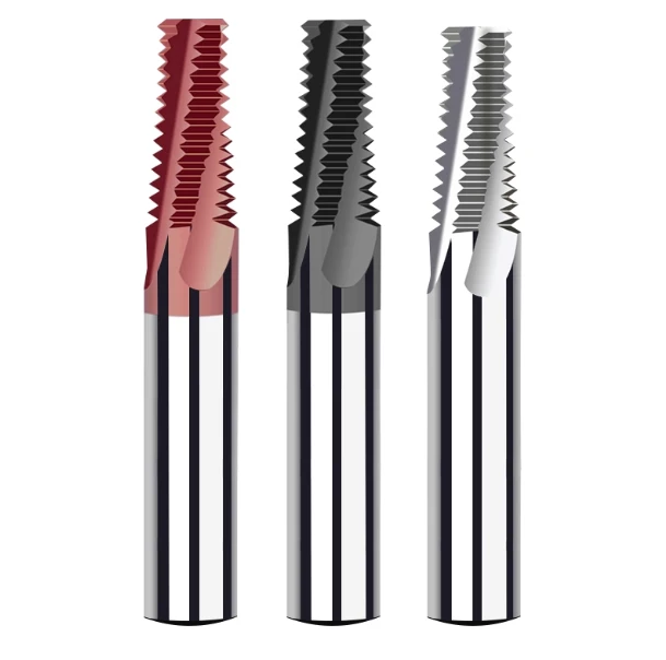
A mold-making shop recently approached us with broken taps embedded in pre-hardened tooling blocks. Tapping seemed economical for the initial low-volume run, but rapid tool wear quickly caused rough surface finishes, torn pitches, and catastrophic tool failure. When a tap breaks inside an expensive cavity, EDM burning is often the only extraction method, inflating production costs and risking part rejection.
This failure scenario is familiar to anyone running complex CNC operations. A thread mill is a rotary cutting tool that generates internal or external threads using 3-axis CNC helical interpolation. Unlike a traditional tap driven straight into a pilot hole, a thread milling tool circles the hole circumference while moving axially at the exact thread pitch.
Machining abrasive alloys, stainless steels, and hardened tool steels drastically limits the operating window of traditional tapping. A solid carbide thread mill distributes cutting forces along radial paths rather than subjecting the entire tool core to massive torsional stress. This mechanical advantage eliminates broken-tool scrap risks, as a worn milling tool simply pulls out of the bore without binding.
Tool longevity and thread pitch accuracy depend entirely on tool design synergy. Sub-micron carbide substrates, specialized PVD heat coatings, and engineered flute helixes allow high-feed circular cutting even above HRC 55. Evaluating a thread milling tool requires matching flute core rigidity, cutting edge preps, and chip evacuation clearance directly to the hardness of your raw workpiece.
Standard tapping forces you to keep dedicated taps for every diameter, tolerance class, and pitch combination. A single thread mill can generate multiple hole diameters as long as the thread pitch remains identical. CNC operators can also adjust cutter compensation offsets on the controller to dial in precise pitch diameter tolerances without changing tooling.
Transitioning from soft alloys to high-hardness tool steels demands an exact understanding of helical toolpath dynamics. Moving into HRC 60+ applications requires specialized cutting edge geometries, rigid machine setups, and precise radial chip thinning strategies. Mastering these baseline dynamics ensures clean threads, minimal spindle load, and predictable tool life across demanding production runs.
What Is a Thread Mill?
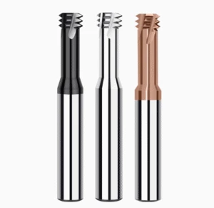
When reviewing part prints with multi-hole patterns, machinists frequently default to selecting standard taps. After evaluating material hardness, thread depth, and part value, an experienced programmer often chooses a solid carbide thread mill instead. Rather than forcing a tool axially into the hole, this tool uses 3-axis CNC helical interpolation to mill the pitch geometry progressively.
Application success requires evaluating far more than raw thread dimensions or pitch tables. Machine rigidity, toolholder runout, hole depth, and substrate coating chemistry dictate whether a tool will survive difficult cuts. In hardened steels, a dedicated thread milling tool reduces cutting pressure significantly, giving operators predictable tool wear instead of catastrophic tap breakage.
Thread Mill Definition: What Is a Thread Mill?
In precision machining, a thread mill is a rotary cutting tool engineered to produce internal or external threads via circular ramping. Unlike taps that screw straight into a pilot bore under direct spindle synchronization, this tool cuts clearance radially while feeding axially. This helical motion generates precision thread forms through controlled, multi-pass material removal.
Field tests show that this material removal strategy provides superior cutting load management. Machining high-hardness tool steels creates extreme torsional stress that frequently snaps rigid taps inside the bore. An engineered thread milling tool sidesteps this failure mode by letting operators dial in radial step-overs, spindle speeds, and feed rates to match setup rigidity.
What Does a Thread Mill Do? Primary Applications of Thread Mills
Machinists deploy a high-performance thread mill when process security, tight pitch tolerances, and chip control outweigh raw cycle speed. When manufacturing intricate mold cores, operators leverage CNC toolpath cutter compensation to adjust pitch diameters on the fly without changing tools. This setup versatility is invaluable for meeting tight Class 3B or 6H thread fit requirements.
Thread mills shine brightest in abrasive alloys, stainless steels, and hardened tool steels exceeding HRC 50. Machining extreme hardness upwards of HRC 60 requires a specialized thread milling tool featuring sub-micron carbide grades, wear-resistant PVD coatings, and positive rake geometries. Proper process evaluation prevents tool deflection and ensures excellent thread surface finishes across deep-hole applications.
How Does Thread Milling Work?
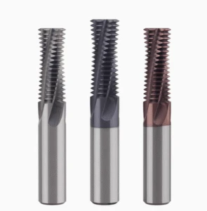
Parts often show dimensional errors, poor flank finishes, or chatter marks even when the cutting tool appears pristine. The root cause usually traces back to mismatched CNC toolpaths rather than poor cutter quality. A successful thread milling operation relies on synchronized tool rotation, continuous circular interpolation, and controlled axial movement to produce accurate thread profiles.
Process stability demands tight coordination among CNC interpolation accuracy, feed rates, cutter core diameter, and alloy hardness. Work-hardening materials require special attention; uneven cutting loads quickly cause edge chipping and premature wear. Skilled machinists verify the programmed toolpath and test radial step-overs before modifying spindle speeds or cutting parameters.
The Thread Milling Process: Helical Interpolation
Helical interpolation is the mechanical core of modern CNC threading. The thread mill enters the bore, executes a precise arc-in move, and sweeps 360 degrees circularly while feeding axially along the Z-axis by exactly one pitch. This multi-axis toolpath forms the full thread geometry through progressive, low-stress radial shearing.
Tool entry and exit routines require careful programming to prevent chatter marks. Using a smooth 90-degree tangential arc roll-in minimizes cutter deflection and eliminates impact shock upon initial workpiece engagement. For deep bores or hardened alloys, pairing this entry motion with high-pressure coolant ensures clean chip evacuation without recutting.
How CNC Thread Mills Machine Internal and External Threads
Machining internal versus external threads relies on identical helical kinematics with reversed directional paths. Internal threading requires piloting the thread milling tool down the hole center before interpolating outward along the inner bore circumference. External operations mirror this movement around the part’s outer diameter, tracing the exterior perimeter with tight radial offset control.
Surface finish defects or pitch diameter variations rarely require throwing away the cutting tool. Checking controller wear offsets, spindle runout, and climb-milling path parameters usually resolves dimensional drift immediately. Rigid setups and calibrated toolpaths are non-negotiable when running hardened steels up to HRC 65, where cutting resistance magnifies deflection.

Types of Thread Mills
Selecting a cutter requires looking past basic catalog sizes to evaluate real-world part behavior. A shop machining diverse mold blocks once ran a single tool style across all features, getting decent results in soft steel but rapid wear in pre-hardened stock. The issue was not tool diameter, but rather mismatching the tool geometry to operational cutting resistance.
Evaluating the different types of thread mills means analyzing workpiece hardness, thread pitch, hole depth, batch size, and machine rigidity. Tool performance hinges on choosing between solid carbide builds, single-profile or multi-profile forms, and internal or external configurations. Matching tool geometry to cutting pressure balances tool life and cycle times in demanding materials.
Carbide Thread Mills
When threading mold steels and high-hardness alloys, experienced programmers rely on solid carbide thread mills. Tungsten carbide substrates maintain exceptional cutting edge integrity under severe thermal loads and abrasive friction. Beyond the basic grade name, flute core strength, edge preparation, and PVD coating chemistry must align with workpiece metallurgy.
Machining hard alloys requires prioritizing edge toughness alongside fracture resistance. Selecting a carbide thread mill for hardened steel requires factoring in spindle taper rigidity, tool overhang, and actual Rockwell hardness. Applications exceeding HRC 60 benefit far more from tailored micro-geometries and multi-layer thermal coatings than from running aggressive surface footage.
Single-Form vs. Multi-Form Thread Mills
Choosing between single-form and multi-form tools comes down to cycle time targets versus operational flexibility. A single-form tool features a single tooth profile that cuts one pitch crest per helical revolution across multiple hole depths. This design lowers tool-pressure deflection on long-reach setups and lets you mill different thread diameters sharing identical pitch profiles.
A multi-form thread mill uses stacked cutting teeth to generate the entire thread depth in one 360-degree helical pass. This configuration slashes cycle times during high-volume batch runs where hole specifications remain static. Because full-depth engagement increases radial cutting pressure, multi-form cutters require rigid setups, stable toolholders, and ample chip evacuation.
Internal vs External Thread Mills
Spatial constraints distinguish internal threading from external operations. Internal milling demands driving the thread mill inside a tight pilot bore where tool core clearance, flute length, and chip evacuation dictate success. External threading operates around the outer part diameter, giving operators easier chip clearance but requiring rigid workholding to avoid vibration.
Dialing in internal or external setups requires tight management of tool runout and CNC interpolation accuracy. On high-hardness steels approaching HRC 65, sudden cutting loads during radial entry or exit will chip sharp carbide edges. Programming a smooth tangential arc ramp minimizes radial shock, preserving cutter longevity across internal and external thread profiles.

Thread Mill vs Tap: What Are the Differences?
Shops handling M6, M8, or larger threaded holes often default to rigid tapping out of habit. As material hardness rises, thread depths increase, or complex parts require multiple thread sizes, tapping can cause high scrap rates, chip packing, and pitch variation. Choosing between a thread mill vs tap requires evaluating workpiece metallurgy, hole geometry, lot size, and machine rigidity.
The mechanical difference centers on cutting motion and chip-load distribution. A tap forces its profile into the core hole through direct spindle-to-feed synchronization, bearing high torsional strain. A thread milling tool generates pitch geometry progressively through 3-axis CNC helical interpolation, eliminating binding hazards and giving programmers complete control over cutting loads.
Differences in Cutting Methods: Thread Mill vs Tap
Comparing cutting mechanics reveals why process outcomes vary so drastically. Once a tap engages the pilot bore, full-profile cutting teeth contact the material simultaneously across deep axial surfaces, producing high radial torque. When evaluating a thread mill vs tap, thread milling clears chips radially with small contact arcs, preventing catastrophic binding in deep holes.
In a recent mold-making job, standard taps kept fracturing unpredictably inside hardened tool-steel cavities. Transitioning the job to a thread mill stabilized cutting forces by splitting the cut across multiple light radial passes. If broken taps plague your floor, inspect spindle torque limits and assess whether helical milling can eliminate tool breakage risks.
Precision, Flexibility, and Tool Life: Thread Milling vs Tapping
Comparing thread milling vs tapping highlights major differences in dimensional control and tool wear modes. Thread milling allows machinists to dial in pitch diameter tolerances down to the micron using controller radius compensation. Taps lack this adjustment, requiring separate physical tooling for different tolerance classes, pitches, and hole diameters.
Tool longevity and failure modes also favor the helical approach in difficult cuts. While high-speed tapping excels in soft alloys, materials above HRC 60 create severe friction that often snaps taps inside expensive parts. A thread milling tool exhibits gradual edge flank wear, ensuring predictable cutter life and eliminating costly EDM extraction downtime.
When to Use a Thread Mill Instead of a Tap?
Knowing when to use a thread mill instead of a tap comes down to balancing part risk against production requirements. Thread mills are preferred when cutting high-hardness tool steels, machining asymmetrical components, threading near blind-hole bottoms, or working on thin-walled parts prone to distortion. The ability to mill clean threads without full-depth contact pressure protects high-value workpieces.
High-volume production runs in standard aluminum or mild steels may still favor synchronous tapping for pure cycle speed. Machining hardened steels exceeding HRC 55 or running tight-tolerance aerospace parts makes a carbide thread mill the superior production choice. Matching tool coatings, core rigidity, and cutter overhang to the cut ensures maximum process security.
Choosing the Right Carbide Thread Mill for Different Materials
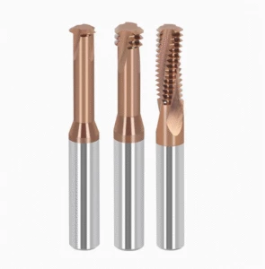
Applying a “one-size-fits-all” tooling approach across varying workpieces leads to inconsistent quality and scrap. Running identical M8 parameters in mold steel, 304 stainless, and 6061 aluminum causes drastically different cutting pressures and chip forms. When choosing the right carbide thread mill for different materials, machinists must match tool substrates, edge preparations, and flute geometries to the workpiece’s physical metallurgy.
Evaluating a workpiece begins with assessing hardness, tensile strength, thermal conductivity, and work-hardening tendencies. Running soft-material geometry on hard steels quickly fractures cutting edges, while using blunt tooling on aluminum creates built-up edge and burrs. Process engineers assess total tool wear, pitch tolerances, and surface integrity across continuous production runs rather than judging single test cuts.
Carbide Thread Mills for Steel
Machining pre-hardened steels like P20 and 718H demands dedicated carbide thread mills for steel built with high-transverse-rupture-strength substrates. Engineered flute profiles ensure smooth chip evacuation while minimizing cutting pressure during helical arcs. Tool overhang and spindle taper rigidity directly determine flank surface finishes, often influencing dimensional consistency more than cutting speed adjustments.
Running mold steels requires active tool wear monitoring during production runs. Premature flank wear or micro-chipping indicates excessive radial engagement or inadequate chip clearance along deep hole walls. Gradually tuning surface footage, chipload per tooth, and radial step-overs keeps cutting forces balanced, ensuring stable pitch tolerances across long manufacturing cycles.
Thread Mills for Aluminum and Stainless Steel
Gummy alloys like aluminum demand ultra-sharp cutting edges and high-polish flutes to prevent chip packing and built-up edge (BUE). Conversely, austenitic stainless steels cause severe work-hardening and thermal buildup at the tool-workpiece interface. Dedicated thread mills for aluminum and stainless steel utilize tailored rake angles and specialized PVD coatings to maintain clean shearing action in these contrasting materials.
Deep-hole threading in 300-series stainless requires continuous chip evacuation and positive cutting action to prevent work-hardened glazing. Operators should inspect chip curl, thread crest finishes, and edge degradation after initial passes to fine-tune toolpaths. Avoiding tool dwell during helical entry and exit prevents localized heat spikes, extending tool life across demanding alloy applications.
Thread Mills for Hardened Steel
Machining mold components above HRC 50 subjects cutting edges to extreme abrasive friction and mechanical impact. Standard cutters fail rapidly under these conditions, demanding specialized thread mills for hardened steel engineered with ultra-fine sub-micron carbide grades and negative micro-chamfer edge preps. Advanced multi-layer heat-resistant coatings like AlTiN or AlCrN protect cutting edges against catastrophic thermal degradation.
When material hardness climbs past HRC 60, toolholder runout and machine rigidity dictate cutting success. Taking multiple light radial passes relieves cutter deflection, preventing premature tool breakage in hard dies and punch blocks. For components reaching HRC 65, dedicated high-hardness geometries must be selected to withstand extreme shearing forces without chipping the tool core.
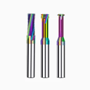
Thread Mills for Hardened Steel: Why Is a Specialized Thread Mill Needed?
Machining threads into tooling components after heat treatment prevents distortion but introduces severe cutting challenges. Standard tooling that runs reliably in pre-hardened stock experiences rapid flank wear and edge micro-chipping once material hardness exceeds HRC 55. High cutting resistance combined with long tool reach amplifies deflection and chatter, quickly ruining pitch profiles.
Success requires matching the tool substrate, cutting edge preparation, and PVD coating directly to cutting loads. Dedicated thread mills for hardened steel feature reinforced tool cores and tailored edge micro-geometries designed to absorb radial shock. Prioritizing cutting edge stability over aggressive cycle times ensures consistent thread pitch accuracy without catastrophic tool failure.
Key Challenges in Thread Milling Hardened Steel
Extreme abrasive friction and mechanical impact represent the primary hurdles when machining high-hardness alloys. As hardness increases, cutting forces skyrocket, making small tool overhangs and minor holder runout triggers for severe chatter. Without a rigid setup, normal micro-wear rapidly escalates into chipped flutes and damaged thread flanks.
Localized heat concentration creates another serious risk during tight interpolation passes. Confined internal thread geometries trap heat near the cutting zone, degrading standard cutting edges through rapid thermal softening. When thread milling hardened steel between HRC 55 and HRC 65, machinists must control radial step-overs and verify pilot hole concentricity to prevent localized overloading.
Adapting Carbide Thread Mills for High-Hardness Materials
Selecting cutters for hardened alloys requires balancing substrate toughness against extreme abrasive wear resistance. Ultra-fine sub-micron carbide grades provide high core rigidity, preventing the structural deformation typical of standard tooling. Edge preps must feature controlled negative micro-chamfers or hones to prevent the chipping that sharp, unprotected edges experience.
Advanced PVD heat-resistant coatings like AlTiN and TiAlSiN shield the cutting edge against severe friction and thermal breakdown. However, a premium coating cannot compensate for improper toolpath kinematics or excessive radial engagement. When optimizing carbide thread mills for high-hardness materials, tracking progressive flank wear patterns helps machinists dial in cutting parameters before dimensional drift occurs.
Key Considerations for Selecting Thread Mills for Hardened Steel
A disciplined engineering workflow ensures repeatable results: Material → Thread Specs → Machine Rigidity → Tool Geometry. Machinists first verify actual Rockwell hardness, hole depth, and pitch tolerance, then evaluate spindle taper rigidity and holder runout. Only then should you select the tool diameter, flute count, and grade when selecting thread mills for hardened steel.
Bore preparation is especially critical when cutting materials harder than HRC 60. Tapered, work-hardened, or undersized pilot holes cause sudden shock loads that snap small-diameter cutters upon initial entry. For components reaching HRC 65, keeping tool reach short, selecting reinforced shanks, and running multiple light radial passes ensures secure, high-precision threading.

HRC65 Thread Mill: Can Thread Mills Be Used on HRC65 Hardened Steel?
Machining threads directly into tool steels hardened to Rockwell 65 is fully achievable with the proper setup. Mold shops often require post-heat-treatment threading on core inserts to eliminate heat-treat distortion and hold tight true positions. Deploying an HRC65 thread mill requires verifying material composition, actual hardness, spindle taper rigidity, and toolholder runout before cutting.
Processing HRC 65 materials eliminates any margin for toolpath or setup errors. Cutting pressures are immense, making standard cutting parameters from HRC 55 applications obsolete due to rapid edge chipping and catastrophic deflection. Success relies on balancing sub-micron carbide core strength, tailored edge preparations, and controlled radial passes to maintain pitch tolerances and thread integrity.
What Makes an HRC65 Thread Mill Different?
A dedicated HRC65 thread mill features structural differences engineered to resist extreme radial loads and abrasive wear. Standard cutters feature sharp positive rakes that immediately fracture when contacting ultra-hard matrix structures. High-hardness thread mills utilize reinforced core diameters, reduced flute depths, and negative micro-chamfered cutting edges to withstand continuous shearing friction.
Managing radial cutting load distribution is vital for small-diameter tooling running in dense, hardened dies. Minimal cutter cross-sections amplify spindle runout and tool vibration, turning slight chatter into broken flutes. Precision machining at this level requires high-rigidity hydraulic or shrink-fit holders to maintain concentricity and maximize cutting edge stability.
Substrate, Geometry, and Coating of HRC65 Thread Mills
Substrate formulation dictates whether a cutter chips or wears predictably under severe cutting pressure. High-performance thread mills for HRC65 hardened steel rely on ultra-fine sub-micron carbide grades enriched with precise cobalt binders to balance fracture toughness against abrasive resistance. Flute geometries feature short cutting lengths to minimize deflection and maintain pitch cylinder squareness.
Advanced nano-composite PVD coatings such as TiAlSiN or AlCrN provide the thermal barrier needed for dry or air-blast machining. These coatings withstand cutting-zone temperatures exceeding 1,000°C while preventing abrasive flank wear. A premium coating cannot offset excessive holder overhang or loose tolerances, making total system rigidity essential.
Which Hardened Steel Threading Applications Are Suitable for HRC65 Thread Mills?
Ideal applications include shallow fastener holes, dowel-pin extraction threads, and precision repair features in hardened die components. Running an HRC65 thread mill in steels like D2, DC53, or SKD11 delivers clean thread flanks without needing slow EDM burning operations. However, deep-hole threads exceeding 2.5 times the cutter diameter drastically increase deflection risks and require multi-pass profiling.
Verifying pilot hole concentricity, hole diameter tolerances, and surface decarburization prevents tool breakage upon initial helical entry. Operators must program multi-pass radial step-overs and tangential arc ramp-ins to distribute cutting pressure evenly. When machine rigidity, toolholder balance, and tool geometry align, thread milling provides a reliable, repeatable solution for ultra-hard workpiece processing.
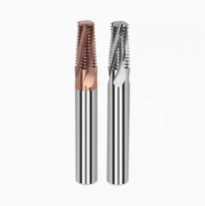
How to Choose an HRC65 Thread Mill Supplier?
Focusing exclusively on catalog unit prices frequently leads to premature cutter failure on the shop floor. Inadequate quality control causes severe runout, chipped flutes, and rapid pitch-diameter drift in high-hardness applications. When learning how to choose an HRC65 thread mill supplier, shops must audit substrate metallurgy, flute grinding precision, PVD consistency, and quality inspection protocols.
High-hardness threading demands complete clarity regarding your machining environment. Before committing to a tooling vendor, define your steel grade, actual Rockwell range, thread depth, and machine-spindle taper. Partnering with a supplier capable of backing up design choices with physical testing data avoids the downtime and high scrap rates caused by generic tooling.
What Manufacturing Capabilities Should an HRC65 Thread Mill Supplier Possess?
Precision manufacturing capabilities separate true high-performance toolmakers from commodity resellers. Grinding an HRC65 thread mill requires multi-axis CNC grinding centers maintaining sub-micron wheel runout and laser-controlled edge-prep stations. Consistent cutting-edge honing and precise h6 shank tolerances prevent the harmonic vibration that instantly fractures carbide in 65 HRC workpiece materials.
Qualified suppliers must explain the functional link between their micro-grain substrate selection and high-temperature PVD coatings. Ask prospective vendors about their non-contact optical inspection procedures and cutting-edge prep tolerances. A supplier possessing verified manufacturing control delivers tools that perform reliably rather than displaying dramatic performance variations between production runs.
How to Choose a Carbide Thread Mill Manufacturer?
Evaluating a carbide thread mill manufacturer requires reviewing both raw material expertise and practical milling experience. Simply owning multi-axis tool grinders does not translate into mastering high-hardness threading dynamics. Manufacturers must understand how specific carbide binders, grain structures, and flute helix designs behave under heavy radial loads in pre-hardened die blocks.
Reputable vendors act as manufacturing partners rather than transactional order-takers. Share your target thread specifications, workpiece metallurgy, tool overhang, and machine capabilities to evaluate their technical support. If a supplier defaults to generic product tables without recommending tailored radial step-overs or coating formulations, seek out an engineer-led tooling specialist instead.
How Do You Evaluate the Precision, Lifespan, and Consistency of an HRC 65 Thread Mill?
Evaluating a tool requires looking past the first hole to assess multi-part production stability. Initial threads often pass pitch-gauge checks, but insufficient edge toughness quickly triggers flank wear, chatter marks, and dimensional drift. Quantify performance using continuous cycle data, including GO/NO-GO gauge retention, flank surface roughness, and uniform wear patterns across multiple parts.
True quality control means verifying batch-to-batch repeatability on identical machining operations. Consistent wear patterns across tool lots prove the manufacturer maintains strict control over their grinding wheels, substrates, and coating recipes. Partnering with a proven supplier guarantees the precision and tool life required to make high-hardness thread milling a repeatable, profitable operation.

FAQs About Thread Mills and Thread Milling
Machinists often ask about tool selection, machining parameters, and tool life when first adopting helical threading. The following questions cover core technical trade-offs between standard tapping, carbide thread mills, and threading hardened tool steels up to HRC 65.
Rather than relying on catalog ratings, evaluate cutting stability using actual workpiece hardness, pitch diameter, hole depth, and machine rigidity. This hands-on evaluation ensures consistent thread tolerances and predictable tool life across production runs.
What Is a Thread Mill?
A thread mill is a rotary cutting tool engineered to generate internal or external threads through 3-axis CNC helical interpolation. Unlike a tap driven directly into a pilot hole, this tool sweeps circularly while advancing axially by one pitch per revolution.
This gradual shearing action minimizes cutting torque and tool deflection during machining. It also allows operators to adjust pitch diameters via CNC cutter compensation, delivering greater versatility across demanding applications.
Is a Thread Mill Better Than a Tap?
Neither tool is universally superior; selection depends entirely on part material, geometry, and production batch size. High-speed tapping excels in high-volume production of standard threads in soft steels and aluminum.
A thread milling tool is superior for difficult alloys, blind holes, large diameters, or high-value parts where tap breakage risks scrap. It enables controlled chip evacuation and eliminates EDM extraction downtime.
What Is the Best Carbide Thread Mill?
The best carbide thread mill is the one matched precisely to your workpiece metallurgy and setup rigidity. Key variables include substrate grain size, core diameter, flute helix, edge prep, and high-temperature PVD coatings.
For hardened alloys, prioritize fracture toughness and thermal resistance over ultra-sharp cutting edges. Proper edge hones prevent micro-chipping under heavy radial loads, ensuring stable pitch tolerances over extended runs.
Can a Thread Mill Cut Hardened Steel?
Yes, a specialized thread mill for hardened steel can reliably cut materials from HRC 50 to HRC 60+. High hardness increases cutting pressure, demanding ultra-fine micro-grain carbide substrates and wear-resistant coatings like AlTiN or AlCrN.
Success requires high-rigidity toolholding, minimal tool overhang, and programmed multi-pass radial step-overs. Controlling radial depth of cut prevents chatter, protects the cutting edge, and ensures precise thread flank geometry.
Can a Thread Mill Cut HRC65 Steel?
Machining HRC 65 steel is fully viable with a dedicated HRC65 thread mill and a rigid setup. The entire system—including machine spindle, shrink-fit holder, and workpiece clamping—must maintain near-zero runout to avoid instant edge chipping.
Programmers must use multi-pass helical interpolation with light radial engagement and smooth tangential arc entry. Maintaining these rigid conditions delivers clean thread profiles in fully hardened dies without requiring EDM operations.
How Do I Choose an HRC65 Thread Mill Supplier?
Look beyond unit pricing and catalog tables when selecting an HRC65 thread mill supplier. Prioritize manufacturers with multi-axis CNC grinding precision, sub-micron inspection protocols, and verified micro-grain carbide batch consistency.
A qualified vendor should review your part drawings, steel grades, hole depths, and machine capabilities to recommend specific tool geometries. Direct technical support ensures reliable tool life and repeatable thread accuracy in ultra-hard materials.






