



We once tackled a demanding project where a customer had to cut multiple internal thread sizes into mold steel. The run included both standard pre-hardened stock and much harder tool steel. They initially picked cutters based purely on thread diameter and nominal pitch. Once chips started flying, tool life collapsed on the harder blocks, chatter surfaced on deep holes, and surface finish degraded rapidly.
That failure reveals a reality seasoned machinists know well: matching catalog numbers to nominal thread dimensions is not enough. You must evaluate the mechanical foundation of the cutter, from single-form versus multi-form profiles to internal and external flute geometries. Substrate grain size, edge preparation, and coating adhesion also dictate whether a solid carbide thread mill survives high-cutting-pressure environments.
Selecting the right thread milling tool types requires matching cutter geometry directly to your setup rigidity, thread depth, and machinability. Single-form cutters reduce radial tool pressure and offer versatility across multiple pitches, making them ideal for unstable setups or high-mix jobs. Multi-form cutters maximize throughput in rigid production runs, though their higher cutting forces demand precise feed-rate control and rigid toolholding.
When you cut threads in hardened steel, standard tool geometries quickly show their limits through rapid micro-chipping and poor thread quality. Extreme cutting temperatures and abrasive tool wear demand rigid carbide thread mill for hardened steel options with optimized core diameters and heat-resistant coatings. Balancing tool reach, flute count, and material hardness keeps thread accuracy high and prevents costly workpiece scrap.
Understanding the various types of thread mills helps you optimize cycle time, eliminate thread pitch errors, and extend cutter life across challenging materials. If you balance frequent setup changes, high-value components, and tough tool steels, selecting the proper tooling architecture protects your margins and stabilizes your machining operations.

What Are the Main Types of Thread Mills?
Selecting cutters on the shop floor never starts with unit cost. Experienced machinists assess thread geometry, material hardness, tool reach, and spindle rigidity first. Overlooking structural differences between various types of thread mills leads to chatter, poor chip evacuation, and premature wear. We classify cutters by forming method, tool substrate, and hole orientation to match your part requirements precisely.
Tool categories address distinct mechanical challenges. Forming profiles dictate cutting pressure, while tool construction determines deflection resistance under heavy radial loads. High-mix jobs demand flexible cutter geometry to maintain tight tolerances across various setups. In contrast, high-volume production requires rigid tools that maximize edge life and process capability.
What Is a Single Form Thread Mill?
A single form thread mill features a single profile tooth, cutting one pitch level per helical interpolation revolution. This geometry generates minimal radial cutting force, which drastically reduces tool deflection on long-reach holes. Machinists can also cut multiple thread diameters and different pitches using the same tool by adjusting CNC program paths.
The main trade-off centers on cycle time rather than cut quality. Machining deep threads pass-by-pass takes longer than running multi-tooth alternatives. However, for thin-walled workpieces, unstable fixtures, or low-volume runs, this tool offers unmatched process reliability. It gives programmers complete control over thread pitch diameter offsets and surface finish.
What Is a Multi-Form Thread Mill?
A multi-form thread mill incorporates multiple cutting teeth along its fluted length to form a complete thread in one 360-degree helical pass. This configuration slashes cycle times dramatically in mass-production environments with fixed thread sizes. Machinists must maintain rigid toolholding and stable workholding to handle the higher cutting pressure generated by full-flute engagement.
When comparing a single form vs multi form thread mill, the best choice depends on setup rigidity and production volume. Multi-tooth cutters deliver unbeatable throughput on rigid machining centers running identical parts. However, if your spindle lacks horsepower or your setup exhibits deflection, the increased radial tool engagement can cause taper errors and chatter.
What Is a Solid Carbide Thread Mill?
A solid carbide thread mill provides the high elastic modulus and thermal resistance required for tight thread tolerances. Solid carbide resists bending forces far better than high-speed steel, which helps eliminate pitch errors in blind holes. Selecting premium sub-micron grades with heat-resistant coatings ensures stable tool life when machining abrasive tool steels.
Cutting hardened metals demands more than standard carbide substrates. Extreme shear temperatures require an engineered carbide thread mill for hardened steel with reinforced cutting edges and advanced multi-layer coatings. Matching the substrate toughness, relief angles, and flute core thickness to your workpiece hardness prevents micro-chipping and protects expensive parts from scrap.
What Is the Difference Between Single-Form and Multi-Form Thread Mills?
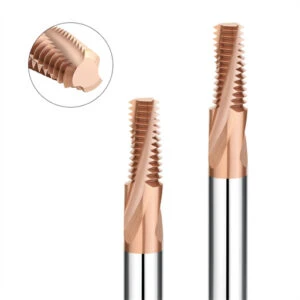
Shops often switch to multi-tooth cutters to reduce cycle times, only to encounter severe chatter and edge chipping. Comparing a single form vs multi form thread mill requires evaluating cutting contact area, radial tool pressure, and chip clearance rather than just tooth count. High-mix jobs favor flexible cutters, while fixed high-volume runs demand rapid cycle times.
Evaluating the machining setup prevents costly mistakes. Multi-tooth cutters engage more surface area per revolution, requiring high spindle torque, rigid workholding, and short tool overhang. Single-tooth alternatives reduce instantaneous tool engagement, which helps eliminate harmonic vibration and thread taper in deep holes.
Characteristics and Applications of Single-Form Thread Mills
A single form thread mill cuts one thread pitch at a time via continuous helical interpolation passes. This architecture offers maximum flexibility for job shops, cutting diverse thread diameters and pitches with one cutter. Machinists can easily fine-tune pitch diameters, program multiple radial spring passes, and hold tight Class 3B tolerances.
Lower cutting forces make these tools ideal for long reach-to-diameter ratios and thin-walled parts. For tough alloys, choosing a rigid single-form thread mill for hardened steel minimizes side-load deflection and tool breakage. Taking multiple shallow helical passes manages cutting heat and keeps edge wear predictable.
Characteristics and Applications of Multi-Form Thread Mills
A multi-form thread mill uses a full-flute cutting profile to machine a complete internal thread in a single 360-degree helical pass. This design dramatically cuts cycle times in high-volume production with dedicated setups. However, simultaneous tooth contact creates significant radial cutting pressure and demands efficient chip evacuation.
Without solid machine rigidity and proper toolholding, multi-tooth cutters cause chatter marks and poor thread surface finish. Chips can easily recut inside deep blind holes, fracturing sharp cutting edges. Machinists must match radial stepover, spindle power, and toolholder clamping force before attempting full-depth production runs.
How to Choose Between Single-Form and Multi-Form Thread Mills?
Choosing between a single form thread mill and a multi-tooth cutter depends on part volume, hole depth, and machine rigidity. Run single-form cutters for prototyping, deep cavities, or unstable workholding setups to avoid tool breakage. Deploy multi-form tools when rigid setups, short thread depths, and high-volume cycles justify the heavier cutting loads.
Extreme material hardness further shifts tooling requirements. Cutting materials above 60 HRC demands rigid, heat-resistant tooling rather than raw cutting speed. Running an engineered carbide thread mill for hardened steel with conservative radial stepovers ensures stable tool life and prevents thread pitch distortion.
Internal Thread Mill vs. External Thread Mill
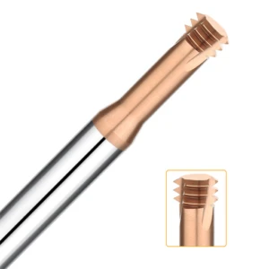
Machinists often focus on thread pitch and nominal diameter while ignoring whether features sit inside a bore or on an outer boss. Comparing an internal thread mill vs. external thread mill requires evaluating tool clearance, chip evacuation paths, and machine envelope limits. Internal cutting confines chips inside tight holes, while external operations demand generous swing clearance to avoid colliding with part shoulders.
Tool kinematics differ significantly between inside and outside diameters. Internal interpolation increases cutter arc-of-contact, raising the risk of tool deflection, taper, and chatter. Conversely, external threading reduces tool contact area, allowing higher chip loads if workholding remains rigid. Evaluating these dynamics ensures reliable thread pitch accuracy and smooth cycle execution.
Internal Thread Mill
An internal thread mill operates inside a pre-drilled minor diameter, forming threads through circular helical interpolation. As hole depth increases and bore diameter shrinks, chip evacuation becomes the primary failure point. Blind holes require high-pressure through-spindle coolant or targeted air blasts to clear swarf and prevent recutting that snaps tool teeth.
When cutting threads in hard mold blocks, thermal control and core rigidity are non-negotiable. Selecting an engineered internal thread mill for hardened steel prevents premature edge failure in deep cavities. Programmers should take multiple radial passes with light stepovers to control heat build-up and maintain precise pitch diameter tolerances.
External Thread Mills
An external thread mill orbits the part’s outer perimeter, making it an excellent alternative to turning threads on mill-turn parts. This approach eliminates the heavy side loads of single-point threading tools, protecting thin-walled tubular components from distortion. Machinists must verify lead-in moves and shank clearance to prevent the tool body from colliding with adjacent shoulders.
Rigid workholding is essential because cutting loads push radially against part features. When selecting an external thread mill for hardened steel, tool deflection and edge chipping remain key concerns on tough alloys. High-hardness jobs demand optimized edge preparations and rigid toolholders like hydraulic chucks or shrink-fit systems to suppress chatter.
How to Choose Between Internal and External Thread Mills?
Selecting between internal and external tools depends on feature location, hole depth, and component geometry. Internal jobs demand careful verification of pre-drill diameters, flute lengths, and chip escape routes to protect blind holes. External setups require confirming that the spindle has adequate clearance around part bosses, clamps, and fixtures.
Workpiece hardness further tightens your operating margins. For parts hardened up to 65 HRC, standard tooling fails quickly under severe cutting friction. Pairing the right cutter geometry with a rigid carbide thread mill for hardened steel ensures consistent thread quality, prevents part scrapping, and maintains dependable tool life across tough production runs.
What Types of Solid Carbide Thread Mills Are Available?
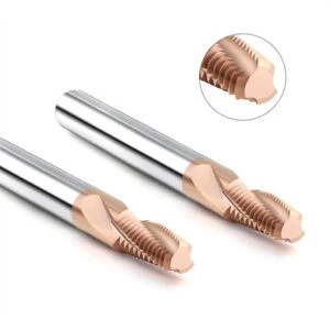
Evaluating types of solid carbide thread mills requires looking past standard catalog material tags. Standard carbide substrates easily micro-chip when machining pre-hardened die blocks if web thickness and edge preps are neglected. Machinists must analyze substrate grain size, core diameter, flute count, and coating adhesion alongside thread pitch to prevent rapid flank wear and pitch drift.
Different cutter styles solve distinct manufacturing problems. Single-form tools provide low cutting forces and pitch versatility for job-shop work. Multi-flute designs slash cycle times on dedicated production lines with rigid setups. When heat-treated die steels exceed 50 HRC, selecting purpose-built tools with reinforced cutting geometries ensures dimensional stability and prevents catastrophic breakage.
Solid Carbide Single-Form Thread Mill
A solid carbide single-form thread mill combines the extreme stiffness of tungsten carbide with a single-tooth profile. This configuration allows CNC programmers to generate multiple thread pitches and diameters using helical toolpaths. It excels in low-volume manufacturing and prototyping, where versatility matters more than high-speed cycle times.
For heat-treated components, using a dedicated single-form thread mill for hardened steel minimizes side-load deflection on deep bores. These cutters feature thick web cores, negative radial rake angles, and eccentric relief to withstand severe cutting forces. Programming multiple shallow radial passes controls cutting temperatures and protects sharp tool crests from chipping.
Solid Carbide Multi-Form Thread Mill
A solid carbide multi-form thread mill uses full-length threading teeth to produce a finished thread in a single 360-degree helical path. These tools typically come in 3-flute or 4-flute styles, often with unequal flute spacing to suppress harmonic chatter. They deliver maximum throughput in high-volume production where setup rigidity and cycle times dominate shop costs.
However, multiple simultaneous cutting edges generate substantial radial tool pressure. If you run long tool overhangs or cut thin-walled housings, this increased load causes tool deflection and tapered threads. Machinists must pair multi-tooth cutters with rigid shrink-fit holders and sturdy workholding to prevent vibration and maintain tight thread tolerances.
Material and Coating Selection for Carbide Thread Mills
Optimizing tool performance begins with pairing the carbide substrate and coating to workpiece hardness. Standard sub-micron carbide grades suit mild steels, but abrasive tool steels require ultra-fine nano-grain substrates with high transverse rupture strength. Proper micro-blunted or honed cutting edges prevent premature notch wear and micro-fractures under heavy chip loads.
Advanced coatings are essential when running a carbide thread mill for hardened steel dry or with high-pressure air blast. Coatings like AlTiN and AlCrN form protective aluminum oxide layers at high cutting zones, shielding the substrate from thermal shock. A premium coating cannot fix excessive tool overhang or spindle runout, but it dramatically extends tool life in rigid setups.
Which Materials Are Suitable for Different Types of Thread Mills?
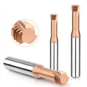
Machining experts rarely pick a cutter first; they examine the workpiece’s metallurgy, shear strength, and thermal behavior. Running 1018 carbon steel, 316 stainless, and 6061 aluminum back-to-back illustrates how radically cutting mechanics shift. Steel demands flank wear resistance, stainless steel induces rapid work-hardening, and gummy aluminum clogs flutes with built-up edge.
Matching workpiece behavior to the correct tool geometry avoids premature failures and costly part scrap. Beyond bulk tensile hardness, programmers must evaluate chip morphology, thermal conductivity, and hole depth ratios. Selecting properly engineered types of thread mills balances cutting edge preparation, flute polish, and coating chemistry against specific alloy dynamics.
Thread Mills for Steel and Stainless Steel
Cutting medium-carbon and pre-hardened alloy steels like 4140 or P20 requires rigid tools with abrasion-resistant TiAlN coatings. Standard carbon steel cuts cleanly when tool core diameter resists side-load deflection during helical circular interpolation. As workpiece hardness increases, machinists should reduce radial stepovers and use climbing cuts to control interface temperatures.
Stainless steels like 304 and 316 pose serious work-hardening risks that quickly destroy cutting edges. Running a dedicated thread mill for stainless steel requires sharp positive rake angles, high-pressure through-coolant, and consistent chip loads. Pausing or rubbing inside the bore instantly hardens the parent metal, accelerating tool wear and chipping cutting teeth.
Thread Mills for Aluminum and Non-Ferrous Materials
Machining aluminum alloys like 6061-T6 and 7075 demands rapid chip clearance rather than extreme tool hardness. Ductile aluminum tends to gall and adhere to flute pockets, triggering built-up edge and severe thread tearing. Utilizing an engineered thread mill for aluminum with mirror-polished flutes and razor-sharp cutting edges ensures smooth chip flow and clean thread crests.
Abrasive high-silicon cast aluminums require specialized hard carbon or DLC coatings to fight flank abrasion. Conversely, free-machining brass and bronze run reliably with bright, uncoated solid carbide cutters to eliminate burrs. Matching spindle RPM and feed per tooth to the alloy’s melting point prevents welding chips inside the flutes.
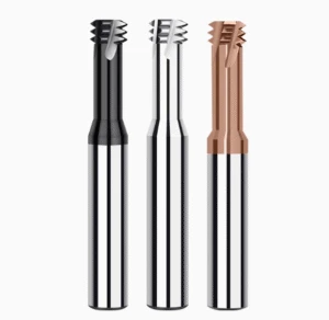
Carbide Thread Mills for Hardened Steel
Threading tool steels hardened from 50 to 65 HRC requires robust tooling to survive intense friction and heat. High radial cutting pressure causes standard micro-grain carbide edges to micro-fracture within a few passes. Machining these demanding alloys requires an ultra-fine submicron carbide thread mill for hardened steel with reinforced negative land geometry.
Thermal control dictates process reliability when milling threads in hardened D2, A2, or CPM steels. High-temperature nanostructured AlTiN coatings shield the carbide core, allowing dry milling with compressed air blasts to evacuate abrasive chips. Running shallow radial stepovers alongside rigid shrink-fit holders ensures tight pitch diameter tolerances and dependable tool life.
How Do You Select the Right Type of Thread Mill Based on Machining Requirements?
Selecting the correct cutter requires evaluating the complete machining envelope rather than simply scanning a catalog table. Pitch diameter, depth-to-diameter ratio, heat-treatment state, and spindle rigidity directly dictate cutter performance. Overlooking setup deflection while picking different types of thread mills leads to severe tool chatter, broken teeth, and tapered pitch errors.
A reliable process matches cutter core thickness and flute reach to the workpiece setup. Machinists must determine the thread orientation, workpiece machinability, and toolholder grip before establishing cutting feeds and speeds. Balancing these foundational variables ensures consistent thread accuracy, clean surface finishes, and dependable tool life across tough production runs.
Selection Based on Thread Size and Thread Profile
Verifying the nominal diameter, pitch, and profile angle determines whether the tool body can clear the minor diameter without rubbing. Small-diameter, deep threads require long overhangs that sharply reduce tool rigidity and increase deflection risks. Machinists must evaluate effective flute length against total thread depth to keep tool reach as short and rigid as possible.
Holding strict tolerances requires fine-tuning diameter offsets and radial stepovers on the CNC control. When running a dedicated thread mill for precision threads, tool runout and machine circularity directly impact final pitch diameter accuracy. Programming multiple radial passes alongside spring passes compensates for tool push-off and guarantees clean thread engagement without burrs.
Choosing Based on Internal or External Threads
Selecting between internal and external thread forms dictates cutter toolpath kinematics and radial clearance. Internal threading forces the tool into a confined bore where chips can easily pack flutes and snap cutting teeth. External threading orbits the part’s outside diameter, which demands generous clearance moves to avoid crashing the cutter body into adjacent shoulders.
Workpiece geometry determines optimal cutter diameter and programming strategies. For external operations, machinists must verify fixture clearance and program smooth arc lead-ins to suppress entry shock. For internal holes, checking pre-drill hole sizes and programming climb-milling circular arcs ensures stable chip flow and protects thread crest integrity.
Choosing Based on Workpiece Material and Hardness
Workpiece metallurgy and hardness dictate the necessary cutting edge preparation, flute geometry, and tool coating. Ductile aluminum alloys demand sharp, polished flutes to resist chip welding, while stainless steels require positive rake angles to prevent work-hardening. Standard pre-hardened steels cut cleanly under moderate chip loads, but high-hardness tool steels quickly punish standard geometries.
When machining mold blocks above 55 HRC, choosing an engineered carbide thread mill for hardened steel is non-negotiable. Sub-micron carbide substrates combined with nanostructured AlTiN coatings withstand extreme cutting temperatures during dry milling operations. Taking light radial stepovers with compressed air blasts prevents thermal cracking and keeps cutting edges stable in 60–65 HRC steels.
Selection Based on Machine Rigidity and Machining Conditions
Even the best cutter fails if the machine spindle, toolholder, or workholding setup lacks dynamic stiffness. Small-diameter cutters with excessive overhang magnify tool deflection, causing tapered threads and premature chipping under radial cutting pressure. Machinists must evaluate spindle taper condition, fixturing rigidity, and toolholder clamping strength before locking in cutting feeds.
High-hardness threading requires extreme setup stability and minimal tool runout to avoid shock fractures. Pairing balanced shrink-fit or hydraulic toolholders with rigid machine setups prevents edge vibration and irregular wear patterns. Optimizing radial depths of cut within a rigid tooling system ensures dependable process reliability and extends tool life across difficult materials.
What Type of Thread Mill Is an “HRC65 Thread Mill”?
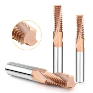
In practical machining, an HRC65 thread mill is not a distinct tool profile, but rather a performance standard designed for extreme hardness. Selecting cutters for 60–65 HRC tool steel requires looking beyond the packaging label to assess core geometry, substrate grain size, and coating thermal stability. You must combine the correct thread profile, pitch, and reach-to-diameter ratio with extreme tool stiffness to avoid sudden edge fractures.
Threading at this hardness level leaves zero room for process instability. Deflection, spindle runout, or harmonic vibration instantly fractures cutting edges and ruins expensive pre-hardened die blocks. Machinists must evaluate toolholder gripping torque, workholding rigidity, and radial chip loads to create a dependable cutting system. True HRC65 machining relies on engineered cutter geometry and controlled tool engagement rather than catalog naming conventions.
Which Thread Mill Is Suitable for HRC65 Hardened Steel?
Selecting cutters for 65 HRC components depends on thread size, feature depth, and production volume. For deep holes or low-volume die details, single-form cutters minimize radial cutting pressure and tool deflection. High-volume runs with fixed pitches benefit from multi-form cutters, provided the spindle, toolholding, and machine setup exhibit high dynamic stiffness.
Clearance and toolpath kinematics also depend on thread orientation. Internal threading requires verifying pre-drilled bore diameters and clearing abrasive chips with high-pressure air blasts. External threading demands generous clearance to avoid collisions with adjacent shoulders. Workpiece hardness sets the baseline, but hole geometry, reach, and setup rigidity determine which thread mill for hardened steel delivers stable results.
Advantages of Solid Carbide Thread Mills for Hardened Steel
A dedicated solid carbide thread mill for hardened steel provides the high elastic modulus and thermal resistance required for extreme hardness. Premium sub-micron substrates resist lateral bending loads, maintaining accurate pitch diameters in small bores. Negative rake angles and reinforced cutting lands protect tool crests from micro-chipping under intense friction.
Thermal wear resistance determines actual tool survival when cutting hardened alloys. Advanced multi-layer AlTiN or AlCrN coatings create an aluminum oxide barrier that blocks cutting heat from softening the carbide core. Taking multiple light radial stepovers controls interface temperatures and extends cutting edge life during demanding production runs.
Selecting Thread Mills for HRC60–HRC65 and SKD11
Threading heat-treated SKD11 or D2 tooling components between 60 and 65 HRC requires careful setup planning. SKD11 contains hard chromium carbides that cause rapid abrasive flank wear on standard cutters. Machinists must choose short-flute tools, run minimal tool overhang, and avoid aggressive radial depths of cut to protect cutting edges.
Fixed cutting parameters rarely work across different SKD11 jobs due to variations in hole depth and setup rigidity. Machinists should verify spindle runout under 0.0001 inches, choose rigid shrink-fit holders, and run dry with compressed air. Dialing in climb-milling circular toolpaths through test passes ensures consistent thread pitch accuracy and eliminates part scrap.
FAQ About Types of Thread Mills
Machinists regularly face critical tooling trade-offs when transitioning between prototype setups and full production runs. Common questions usually center on balancing tool rigidity, selecting between single and multi-tooth profiles, and cutting extreme workpiece hardness. Navigating the diverse types of thread mills requires matching physical part geometry and machine kinematics rather than trusting catalog tables alone.
A dependable machining process balances thread depth, tool overhang, workpiece hardness, and spindle rigidity. Overlooking any single mechanical factor can cause severe harmonic chatter, pitch taper, or sudden edge chipping. Evaluating these core engineering variables together ensures stable cutting, tight pitch diameter tolerances, and predictable tool life across all shop operations.
What Are the Main Types of Thread Mills?
Thread mills are broadly classified by profile geometry, tool substrate, and machining direction. Primary categories include single-form and multi-form cutters, internal and external designs, and solid carbide or indexable tool bodies. These classifications often overlap in a single tool, such as a multi-flute solid carbide thread mill engineered specifically for cutting internal blind holes.
Choosing the proper configuration depends on production volume, setup rigidity, and part features. High-mix job shops frequently choose single-form tools for pitch versatility across low-volume orders. In contrast, dedicated high-volume production setups run multi-form cutters to achieve the lowest possible cycle times per hole.
What Is the Difference Between Single Form and Multi Form Thread Mills?
Comparing a single form vs multi form thread mill comes down to cutting pressure and cycle time. Single-form tools cut one thread pitch per helical revolution, creating minimal cutting force and zero taper on deep holes. Multi-form tools feature a full row of teeth that cuts the entire thread depth in a single 360-degree helical pass.
Multi-form cutters dramatically improve production throughput when running fixed thread sizes on rigid machining centers. However, their larger cutting contact area requires rigid toolholding and stable workholding to prevent chatter. Single-form cutters remain the premier choice for long overhangs, thin-walled workpieces, or low-horsepower machine setups.
What Is the Difference Between Internal and External Thread Mills?
The main distinction between an internal thread mill vs. external thread mill lies in toolpath kinematics and clearance envelopes. Internal thread mills enter a pre-drilled bore, where chip evacuation is restricted and tool deflection risks are high. External thread mills orbit the outer diameter of a workpiece, demanding adequate swing clearance around part shoulders and fixtures.
Internal threading requires verifying minor hole diameters and using high-pressure air blasts to prevent chip recutting. External threading reduces the tool’s arc of contact, which lowers cutting pressure and allows heavier chip loads. Machinists must evaluate part geometry, tool reach, and machine stroke limits before finalizing tool selection.
Is a Solid Carbide Thread Mill Better for Hardened Steel?
Solid carbide is essential when milling threads in metals hardened past 50 HRC due to its exceptional modulus of elasticity. A dedicated carbide thread mill for hardened steel resists lateral tool deflection far better than high-speed steel alternatives. This structural stiffness maintains tight pitch diameter tolerances and prevents thread taper in deep holes.
Substrate grade and edge preparation are just as critical as the base material itself. Machining hardened dies requires ultra-fine sub-micron carbide grades paired with heat-resistant coatings like AlTiN or AlCrN. Honed cutting edges and rigid toolholding suppress chatter and prevent micro-fracturing under intense friction and thermal load.
What Type of Thread Mill Is Best for HRC65 Steel?
Machining 65 HRC tool steel requires an engineered thread mill for hardened steel featuring a reinforced core and negative cutting rake. Single-form solid carbide cutters are generally best because they drastically reduce cutting pressure on the machine spindle. Their small contact zone helps dissipate extreme cutting friction and prevents edge chipping in abrasive alloys like SKD11.
Success at this hardness level depends on running rigid shrink-fit holders and short tool overhangs. Machinists should program shallow radial stepovers using climb milling and dry air blasts to evacuate abrasive chips cleanly. This balanced setup controls cutting temperatures, prevents thread pitch drift, and protects expensive hardened workpieces from scrap.






