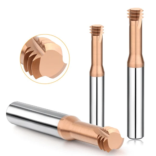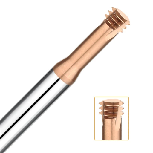
We recently handled a thread machining project involving hardened steel above HRC 60. The customer needed to produce internal threads in small-diameter, deep holes. The initial tool did not fail immediately. Instead, thread dimensions gradually drifted, minor edge chipping appeared, and surface quality declined after several machining cycles.
The customer initially suspected the cutting parameters. We checked the spindle speed, feed rate, radial engagement, and other thread milling parameters. However, the real problem was not a single parameter. We found a mismatch between the tool diameter, edge geometry, tool overhang, and spindle runout. The original thread mill for hardened steel was not well matched to the actual machining conditions.
We have encountered similar situations in many projects. When machining HRC 60–65 hardened steel, SKD11, and other hardened mold steels, a tool that can physically cut the material is not necessarily the right tool for production. Thread accuracy, edge stability, surface finish, and thread mill tool life all depend on how well the tool matches the complete machining setup.
For this reason, we do not evaluate the best thread mill for hardened steel based on one specification alone. We look at the carbide substrate, edge preparation, coating, flute geometry, tool diameter, cutting length, and shank design. We also consider the machine tool, holder, thread size, hole depth, and workpiece hardness.
This becomes especially important when comparing HRC 60, HRC 62, and HRC 65 applications. A small M4 deep-hole thread places very different demands on a tool than a shallow M10 thread. Tool diameter, radial engagement, cutting speed, feed rate, and overhang may all need to change. The same HRC 65 thread mill cannot automatically deliver the same results in every application.
Tool runout is another factor we frequently check. It is easy to overlook because excessive runout may not produce visible tool damage at the beginning. However, even small runout can create uneven cutting loads between the flutes. In hardened steel, this can accelerate edge wear, increase chipping risk, and reduce thread accuracy.
When we validate tools for European and American machining customers, we therefore test the complete system rather than the tool alone. We examine tool geometry, carbide grade, coating, dimensional accuracy, clamping stability, and actual cutting performance. We also compare the results under defined machining conditions instead of relying only on catalog specifications.
For customers running high-volume production, consistency becomes even more important. We look at tool-to-tool dimensional variation, batch stability, achievable thread tolerance, and actual thread mill tool life. These factors help determine whether a manufacturer can provide a reliable solution for HRC 60–65 hardened steel rather than simply supplying a tool that can cut the material.
If you are machining hardened steel in the HRC 60–65 range, the key question is not simply whether a thread mill can cut the material. The more important question is whether the tool can maintain thread accuracy, edge integrity, surface quality, and stable tool life under your actual machining conditions. That is where proper thread mill for hardened steel selection becomes critical.
Best Thread Mill for Hardened Steel: Determining Suitability Based on Actual Operating Conditions
Finding the best thread mill for hardened steel (HRC 60–65) is never as simple as picking a premium grade off the shelf. In our shop, we evaluate the complete setup before touching a tool: heat-treat uniformity, thread pitch, gauge length, machine rigidity, and toolholding. Machining tool steels like SKD11 or D2 demands confirmed hardness consistency. If local hard spots exist, two workpieces rated at HRC 62 can generate completely different radial cutting pressures, quickly degrading the cutting edge.
That is why we always define the operating environment first. Deep-hole hardened steel threading demands maximum core strength, minimal tool overhang, and runout under 3 microns. In contrast, shallow, large-diameter threads offer wider setup latitude. Selecting the right thread mill is not a catalog comparison; it is about matching tool deflection limits and cutting forces to your actual setup to maintain repeatable pitch diameters.
Key Operating Conditions We Verify First for HRC 60–65 Hardened Steel Threading
Before selecting a tool geometry, we verify several easily overlooked prep conditions. We confirm the actual post-quench hardness, thread pitch, and especially pilot hole diameter. In steels hardened to HRC 60–65, an undersized pilot hole drastically increases material removal. This spikes radial forces, leading to immediate tool deflection or catastrophic chipping. We also assess machine spindle dynamics, shrink-fit clamping, and high-pressure air blast delivery.
During a past mold project cutting deep M6 threads in HRC 62 steel, minor vibration caused dimensional drift after just thirty parts. The tool geometry was fine, but excessive shank overhang was flexing under cut. Trimming the stickout and switching to high-pressure air cleared the chips, immediately stabilizing thread tolerances. Always audit your setup rigidity and hole preparation before blaming the cutting tool or programming.
Determining the Tool Selection Range Based on Material Hardness, Thread Specifications, and Hole Depth
We establish baseline tool metrics around the exact hardness rating (HRC 60, 62, or 65) and then constrain the choices by thread depth. Small-diameter internal threads require thick web cores to resist deflection, while deep features require short neck reliefs and precise tool reach. Running an overly slender tool down a deep hole introduces chatter and edge chipping, regardless of how advanced the coating is.
Thread diameter dictates your real-world cutting strategy. Threading an M8 profile in shallow HRC 65 plate allows for a robust tool body and higher chip loads. Conversely, an M4 profile in a deep bore is vulnerable to minor spindle runout and cutting drag. For HRC 60–65 hardened steel threading, prioritize short flute lengths and rigid carbide substrates rather than trying to force a general-purpose tool to fit.
Why the Same Thread Mill Performs Differently at Different HRC Hardness Levels
A tool running smoothly at HRC 58 experiences a steep jump in tool wear at HRC 62, and edge breakdown accelerates dramatically by HRC 65. The tool does not suddenly fail; rather, higher material hardness drastically increases cutting temperatures and shear stress along the microscopic cutting edge. On sub-millimeter thread crests, minor micro-chipping immediately causes gauge failure and rough surface finishes.
Because wear curves are non-linear, never extrapolate HRC 65 tool life from HRC 60 performance data. We monitor live spindle load, cutting harmonics, and optical edge wear across actual test cuts. For continuous runs in HRC 65 steel, optimize your radial depth of cut across multiple passes based on live chip inspection rather than relying entirely on catalog feeds and speeds.
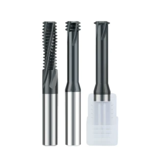
Thread Mill Geometry: Selecting Tool Geometry for Hardened Steel (HRC 60–65)
Optimizing thread mill geometry is critical when cutting extreme materials in the HRC 60–65 range. In our shop, we calculate the core cross-section, cutting edge prep, and chip clearance long before selecting a tool profile. Standard catalog thread mills frequently suffer micro-chipping on HRC 65 tool steels after just a few holes, causing immediate thread gauge failure. Addressing this requires re-evaluating the actual edge geometry rather than just dialing back speeds and feeds.
Machining high-hardness steel is a delicate balance between tool rigidity and edge sharpness. The cutting edge needs enough hone to resist chipping without pushing cutting pressures through the roof. When selecting a carbide thread milling tool, evaluate web thickness, flute length, helix angle, and overall stickout. In continuous HRC 65 production, uniform chip load across the entire cutting profile always trumps aggressive cycle times.
Selecting Thread Mill Geometry Based on Thread Dimensions and Cutting Loads
We determine tool profile by comparing thread pitch against calculated radial cutting pressures. Small-diameter internal threads demand extra caution because the web thickness is inherently compromised. Deep holes exacerbate this issue, turning minor spindle runout into destructive chatter under high cutting loads. In contrast, larger or shallower threads allow for thicker tool cores and much more rigid cutting edge geometries.
During a past HRC 62 mold project, a customer struggled with uneven flank wear across multi-part runs. The culprit was a generic tool profile that concentrated heavy cutting loads onto isolated tooth crests. Switching to an application-specific thread mill geometry with a reinforced core and multi-pass radial programming solved the wear problem. Tool decisions should always reflect hole depth, pilot bore tolerance, and machine rigidity.
Real-World Performance of Single-Tooth, 3-Tooth, and Full-Tooth Thread Mills in Hard Steel Machining
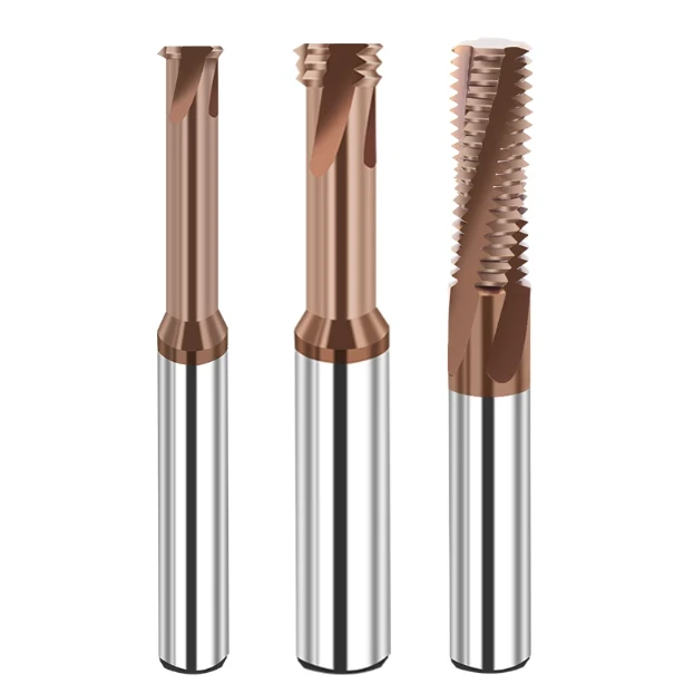
Single-point, three-tooth, and full-profile thread mills behave very differently when cutting hardened materials. Single-tooth tools minimize tool pressure and radial deflection, making them ideal for small holes and tight thread tolerances despite longer cycle times. A 3-tooth tool strikes a practical middle ground, balancing tool deflection with efficient cycle times for batch runs. Full-profile cutters complete threads in one pass, but they demand exceptional machine rigidity and low spindle runout.
When cutting HRC 65 steel, the optimal choice depends strictly on hole depth and setup stability. For deep holes and sub-M6 threads, single- or three-tooth designs help prevent cutter deflection and premature breakage. Full-form cutters should be reserved for shallow holes in rigid machine setups with high-clamping holders. When selecting a thread mill for HRC 65, consistent pitch diameter and steady edge wear matter far more than tooth count alone.
How Flute Length, Helix Angle, and Core Diameter Affect Thread Mill Stability in HRC65 Material
Flute length directly dictates whether an HRC65 material setup will run smoothly or suffer high-frequency chatter. We often see operators pick excessive flute lengths to ensure bottom-of-hole clearance, inadvertently sacrificing tool stiffness. In one instance, shortening the cutter neck and matching flute length to actual thread depth immediately eliminated chatter harmonics. Never use excess flute length as a safety cushion; every millimeter of overhang degrades tool life.
Helix angle and web diameter must work together to clear chips while preventing deflection. An undersized core bends under high shear stress, causing tapered pitch diameters. However, overly thick cores choke chip evacuation, which causes recutting and edge fracture in hardened alloys. For deep-hole operations, proper thread mill geometry prevents chatter and runout from destroying your cutting edges prematurely.
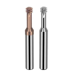
Thread Mill Size: How We Select the Right Tool Size Based on Thread Specifications
Premature tool failure in hardened steel (HRC 60–65) rarely comes down to material hardness alone. In our shop, premature breakdown usually points to an improper thread mill size for the operating envelope. We first evaluate thread pitch, full thread depth, minor diameter tolerance, and rapid-retract clearance before picking a cutter. Treating standard sizes like M4, M6, or M8 identically across different hole depths is a fast track to broken carbide.
Rigidity is everything when threading hardened alloys. Undersized cutters lack the web thickness to resist bending forces, while oversized tools choke chip flow in the minor diameter. The ideal thread mill for hardened steel maximizes cross-sectional area while preserving clearance for chips and smooth lead-in arcs. We always select the beefiest cutter core that can safely enter the hole without rubbing the flanks.
Matching Thread Mill Size to Specifications Like M4, M6, and M8
Selecting tool dimensions is never a one-size-fits-all formula. For an M4 thread, the tight minor diameter severely limits the tool’s core diameter, drastically reducing bending stiffness in deep holes. An M8 application offers far more clearance, allowing for a thicker shank, multi-flute body, and heavier chip loads per tooth. Matching the thread mill size to the pilot hole volume prevents excessive radial tool deflection.
In an HRC 62 mold core run involving blind M6 threads, the original tooling chipped rapidly during production. The root cause was an oversized tool envelope that choked chip ejection and spiked cutting loads. Switching to an application-specific carbide thread milling tool with a relieved neck and multi-pass radial stepover immediately stabilized thread pitch consistency. Always balance tool diameter against actual chip space rather than relying on basic catalog charts.
Common Issues When Machining HRC 60–65 Steel with Small-Diameter Thread Mills
Small-diameter cutters running in HRC 60–65 steel face constant threats of micro-chipping, harmonic chatter, and sudden shank breakage. In sub-M5 applications, the fragile web core combined with extended stickout drastically cuts dynamic system rigidity. A setup might thread the first hole within spec, only to wander out of pitch tolerance on the fifth part. When pitch diameters drift, we check spindle runout and flank wear before blaming the workpiece hardness.
Pilot hole condition also makes or breaks small-hole threading. If a prior solid-carbide drill created a work-hardened skin or an undersized bore, radial forces skyrocket on cutter entry. Sudden cutting spikes cause micro-fractures along sub-millimeter cutting edges in HRC 65 steel. To stabilize the cut, dial in gentle helical roll-in entries and conservative thread milling speeds and feeds before pushing for faster cycle times.
Selecting Tool Diameter and Effective Cutting Length for Deep Holes, Long Overhangs, and Confined Spaces
For deep-hole threading, we calculate the absolute minimum reach required and work backward to design the tool body. Never run extended flutes just to be safe; extra reach kills rigidity exponentially through the length-to-diameter ratio. In tight cavities, verify the neck relief transition, shank step, and part clearance. The primary physical constraint on tool selection is often the surrounding pocket walls rather than the thread size.
Excessive tool overhang turns moderate cutting loads into severe deflection and premature edge wear. In a deep M6 project, the customer assumed they needed an extra-long shank to reach bottom-of-hole depth. We redesigned the setup with a relieved neck tool held short in a hydraulic chuck, drastically cutting unsupported overhang. Optimizing tool reach this way stabilizes cuts far more reliably than simply swapping to a more brittle, high-hardness carbide thread milling tool.
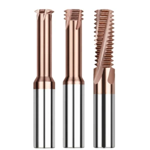
Carbide Thread Milling Tools: How We Select Tools for Machining HRC 60–65 Steel
Selecting high-performance carbide thread milling tools for HRC 60–65 steel goes far beyond reading catalog hardness charts. In our shop, we evaluate substrate toughness, edge prep, and real-world cutting harmonics as a connected system. Small-diameter cutters have very little cross-sectional area, making them susceptible to micro-chipping in hardened alloys. A standard micro-grain tool might pass the first few parts, but the edge will round quickly, throwing off pitch diameters and surface finish.
When machining HRC 65 mold components, harder is not automatically better. Substrates optimized strictly for wear resistance are brittle and fracture easily during entry shock, interrupted cuts, or minor spindle vibration. We look for a balanced tungsten carbide formulation that pairs transverse rupture strength with high thermal stability. The right cutter must sustain radial cutting loads while holding a sharp, chip-resistant cutting line throughout long production runs.
Why We Prioritize Substrate and Edge Stability in Carbide Thread Milling Tools
Tool breakdown in hard-part machining rarely happens without warning. The cutting edge typically develops microscopic flank wear or crest micro-chipping first, causing cutting forces to spike before the tool snaps. In small threads, even five microns of edge breakdown will cause thread go-gages to bind. We inspect used tools under a toolmaker’s microscope to analyze wear land width, chipping patterns, and root degradation instead of just counting broken cutters.
During an HRC 60–62 production run, a client’s tools began failing go/no-go inspection after thirty holes despite looking acceptable to the naked eye. Magnification revealed microscopic chipping along the thread crests. Switching to balanced-toughness solid carbide thread mills with a controlled edge hone and tuned radial stepovers completely stabilized their pitch diameters. Never evaluate a tool grade on specs alone; prioritize edge stability under load.
Real-World Performance of Ultra-Fine Grain Carbide in HRC 60–65 Steel
Using ultra-fine grain carbide provides the edge retention and compressive strength needed to machine through HRC 60–65 die steels. The dense, refined grain matrix allows tool grinders to produce a sharper, stronger cutting edge without micro-notches. When machining hardened SKD11 or D2, this grain structure keeps sub-millimeter thread crests sharp and dimensionally accurate through tough helical interpolation paths.
Substrate quality alone cannot overcome poor setup habits. Long tool stickout, excessive runout, or undersized pilot holes will break premium carbide cutters just as fast as budget ones. On an HRC 65 stamping die job, switching to a premium substrate extended tool life, but eliminating collet runout doubled it. Always evaluate carbide performance alongside your holders, tool reach, and machine dynamics.
The Practical Relationship Between Coatings, Edge Preparation, and Thread Mill Life for Hard Steel Applications
Coatings for hard steel threading must resist extreme friction, oxidation, and heat buildup above 1000°C. Milling HRC 60–65 material concentrates intense heat right at the cutting interface. If the PVD coating fails to isolate the carbide, thermal cracking and abrasive flank wear destroy the profile fast. Match high-aluminum coatings like AlTiN or AlCrN to your cooling method, radial depth of cut, and surface footage.
Edge prep is the final factor that determines thread mill life. Razor-sharp edges cut freely initially, but they chip instantly when hitting tool vibration or hard inclusions. Applying a microscopic controlled hone strengthens the edge wedge, producing predictable, steady wear patterns over hundreds of thread passes. For critical HRC 60–65 setups, establish your optimal coating, edge prep, and chip load balance through controlled test cuts.
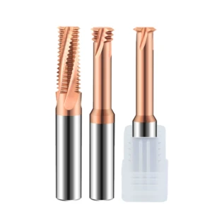
Thread Milling Speed and Feed: Adjusting Actual Cutting Parameters for HRC 60–65 Hardened Steel
When cutting threads in HRC 60–65 tool steels, never plug catalog parameters straight into your CNC control. In our shop, we dial in a conservative baseline using cutter diameter, thread pitch, hardness, and gauge length. Then, we make single-variable adjustments while reading spindle load, tool acoustics, and chip formation. Small-diameter cutters offer minimal margin for error; changing multiple feed or speed values simultaneously obscures the root cause of edge failure.
On an HRC 62 mold block project, a programmer ran standard speeds and feeds that destroyed edges after four holes. The issue was an aggressive radial stepover overloading the cutter’s fragile crests. We split the cut into three radial passes, re-calibrated the surface footage, and stabilized tool life immediately. Optimum thread milling speed and feed rates are never fixed numbers—they represent an operating window you dial in around system rigidity.
Adjusting Thread Milling Speed and Feed Based on Tool Diameter, Thread Dimensions, and HRC Hardness
Setting parameters begins by evaluating core web diameter against required thread pitch. Small-diameter tools have fragile cross-sections, so pushing excessive surface footage generates heat that breaks down carbide binders. We never apply identical settings across HRC 60, 62, and 65 workpieces; cutting loads jump non-linearly as hardness climbs. As hardness rises, monitor cutting acoustics and edge wear rather than relying purely on gross spindle load meters.
Pitch and pilot bore tolerances also dictate your cutting speeds and feeds. Coarser pitches produce significantly higher tool engagement, requiring lighter radial stepovers to prevent tool deflection. An undersized drilled hole forces the tool to machine excess stock, instantly spiking radial pressure. When programming thread milling parameters for hardened steel, establish cutting stability first with controlled multi-pass stepovers before chasing cycle time reductions.
How RPM, Feed, and Radial Depth of Cut Affect Cutting Loads When Thread Milling HRC65 Steel
Simply ramping up spindle speed rarely improves cycle times in HRC 65 material. If RPM, internal feed rate, and radial depth of cut are out of sync, tool pressure spikes and chips work-harden the cut. Multi-tooth cutters suffer heavily from this; increasing feed at high RPMs multiplies tool pressure per tooth instantly. When radial depth of cut is too aggressive, instantaneous cutting loads snap fragile thread crests.
On an HRC65 thread milling setup, an operator faced shrill chatter and micro-chipping on the lead teeth. Rather than dropping spindle speed, we reduced radial depth of cut and reprogrammed the internal arc feed to stabilize tooth engagement. The machine harmonics smoothed out immediately, and pitch diameters held repeatable tolerances. When machining high-hardness alloys, balancing radial engagement with tooth chip load is far more effective than tweaking single parameters.
Adjusting Parameters in Response to Edge Chipping, Chatter, or Thread Dimension Drift
When cutting edges chip, inspect holder runout, stickout length, and pilot bore size before changing feeds. If high runout is the true root cause, dropping the programmed feed rate only causes rubbing and accelerates thermal breakdown. For HRC60–65 steels, reduce radial depth of cut first and add a spring pass to check if pitch dimensions stabilize before adjusting surface footage.
If harmonic chatter appears, inspect tool overhang, shrink-fit holder balance, and part clamping stiffness. When thread pitch diameters drift, look for flank wear and thermal expansion rather than assuming programming errors. In a continuous production cell, pitch drift was initially blamed on excessive feed, but inspection revealed five microns of holder runout. Real-world stability comes from matching tool runout tolerances to your thread milling speed and feed strategy.
Thread Mill Runout: Controlling Runout Issues When Threading HRC65 Hardened Steel
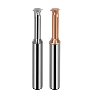
When cutting threads in HRC65 hardened steel, dimensional drift often occurs even when tool quality, material batches, and feeds look perfect. Troubleshooting typically points straight to total indicated runout (TIR) across the tool assembly. With small-diameter cutters, microscopic runout forces a single cutting edge to take the entire chip load while opposing flutes cut air. Over continuous cycles, this uneven load causes severe unilateral wear, micro-chipping, pitch diameter drift, and broken cutters.
In high-hardness setups, treating thread mill runout as an essential verification step prevents costly part scrap. We evaluate dynamic runout across the machine spindle, toolholder precision, collet cleanliness, and gauge stickout. For precision applications, focus on the true coaxiality of the entire clamped assembly rather than just factory tool specs. Dialing in your assembly runout solves dimensional drift far faster than simply buying a more expensive cutter.
How We Check Thread Mill Runout in Practice
We measure the cutter, toolholder, and spindle interface as one complete assembly. After clamping the tool, we sweep an ultra-precision indicator at two distinct spots: on the shank near the nose and directly at the working cutting flutes. If runout reads clean near the holder but multiplies at the tip, we check tool overhang and body straightness. Measuring at the cutting teeth is non-negotiable for small tools, as tip runout dictates the actual tooth impact forces.
During an HRC62 die project, a client snapped two consecutive premium cutters while chasing pitch tolerances. The tools were flawless in the box, but measured over 12 microns of thread mill runout once chucked into the spindle. Wiping the spindle taper clean, replacing a worn collet, and choking up on the overhang immediately stabilized thread pitch dimensions. Always distinguish between bare tool runout and clamped assembly runout before blaming tool carbide grades or speeds.
Why Slight Runout Significantly Affects Thread Precision and Tool Life in HRC65 Materials
Small-diameter cutters running in HRC65 materials offer zero forgiveness for dynamic runout. Because sub-M6 cutters have minimal web mass, they cannot absorb uneven cutting resistance without flexing. When runout is present, the lead tooth takes a punishing impact on every revolution while the remaining flutes do nothing. In 65 HRC alloys, this focused shock loading quickly causes micro-fractures on the crests instead of normal, progressive abrasive flank wear.
We routinely see this dynamic in production: parts start within go-gage limits, but pitch diameters drift out of tolerance within ten holes. As the overloaded tooth breaks down, cutting pressures skyrocket, accelerating taper and thread pitch errors. Increasing feeds or adjusting passes to compensate only speeds up tool failure. For tight-tolerance hardened steel threading, eliminate mechanical runout before adjusting your cutting parameters.
How Tool Holders, Clamping Methods, and Overhang Affect Thread Mill Runout
Even a premium carbide tool will fail if the clamping interface lacks rigidity and concentricity. Contaminants inside the collet bore, worn taper faces, and uneven clamping torque destroy assembly concentricity instantly. When milling HRC65 tool steel, ditch worn ER collets in favor of high-precision hydraulic chucks or shrink-fit holders. High-hardness materials turn minor holder inaccuracies into violent cutting harmonics and chatter marks.
Excessive gauge length is the biggest contributor to cutting deflection and runout errors. Machinists often run extended tool stickout for visual clearance, drastically reducing dynamic bending stiffness. Under radial cutting pressure, long overhang flexes the tool tip, multiplying measured runout and inducing harmonic chatter. Keep tool reach strictly to the required thread depth to control thread mill runout and protect cutter life.
Thread Mill Life: Determining Tool Life Based on Actual Machining Results
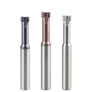
Evaluating thread mill life in HRC 60–65 hardened steel requires looking far beyond a simple hole tally. In production environments, we track complete machining cycles, thread pitch data, cutting parameters, and real-time wear progression. We monitor the exact inflection point where pitch diameters begin to drift toward tolerance boundaries. Pushing a worn tool until it fails risks scrapping an expensive heat-treated mold block.
On a production mold project involving HRC 60+ tool steel, the customer ran tools until catastrophic failure. While cutters did not immediately snap, parts began failing thread go/no-go gauge checks intermittently during the run. Microscopic inspection showed severe flank breakdown that increased radial tool deflection. True tool life is defined by holding certified tolerances and clean thread flanks across the entire production batch.
How We Track Thread Mill Life for HRC 60–65 Hardened Steel
Our machinists maintain a detailed cutting log for every production run on hardened tool steels. We log workpiece hardness, thread pitch, gauge length, spindle surface footage, radial stepover, and thread count intervals. In high-hardness alloys, we actively inspect for flank wear lands, micro-chipping along thread crests, and harmonic sound changes. These early warning signs appear long before total tool fracture occurs.
For batch verification, look deeper than total hole counts across different machine setups. We often see identical cutters show wide tool-life swings across different steel heats due to slight core hardness variations. Tracking material lots, heat-treat certs, and machine rigidity alongside wear data gives actionable operational feedback. Reliable machining logs simplify fine-tuning your thread milling parameters for hardened steel on future setups.
What Do Tool Wear, Chipping, and Changes in Thread Dimensions Indicate?
Distinguishing between normal flank abrasion and sudden micro-chipping is vital when evaluating tool wear. Gradual edge dulling combined with slow, predictable thread gauge drift indicates standard abrasive wear. Conversely, sudden localized chipping and abrupt pitch diameter shifts point to excessive runout, heavy chip loads, or spindle vibration. In HRC 65 materials, running a chipped cutting tooth rapidly destroys subsequent thread profiles.
We correlate optical tool inspection directly with thread gauge results on the shop floor. When a cutter exhibits minor flank wear but holds pitch diameters consistently, we keep running within monitored limits. However, if tooth crests round off and push the thread near the limit, we pull the tool early. Deciding to replace a carbide thread milling tool depends entirely on physical thread quality, not whether the tool looks intact.
Why “Number of Holes Machined” Alone Cannot Determine a Thread Mill’s True Service Life
Relying solely on hole counts to define cutter endurance gives a misleading picture of actual performance. Threading an M4 blind hole at 2.5xD imposes far higher cutting loads and heat than a shallow M10 through-hole. Wear rates also accelerate drastically between HRC 60 and HRC 65 alloys. Minor variations in pilot hole tolerances, holder overhang, and machine rigidity will skew hole totals significantly.
In our shop tests, a cutter producing high part counts in shallow holes wore out rapidly when moved to deeper holes in harder steel. Judging tool performance purely by hole volume leads to flawed tooling decisions. We define effective thread mill life as the number of consecutive threads passing dimensional and surface inspection. Consistent, repeatable thread tolerance is the only metric that matters in hardened alloy production.
Evaluating Continued Tool Usage Based on Cost-per-Hole, Stability, and Tool Change Frequency
Calculating cost-per-hole requires weighing initial tool price, changeover downtime, and the scrap risk of hard-milled parts. A premium cutter that maintains repeatable pitch diameters and reduces offset adjustments is far cheaper than a budget tool that chips constantly. Frequent downtime to reset tools, recalibrate offsets, and run test pieces quickly erodes any initial tooling savings.
We determine real-world tool economy by combining part cost with overall process capability. When a cutter reaches its planned wear limit but runs cleanly, we retire it predictably according to scheduled change intervals. If edge chipping or dimension drift introduces part scrap risks, we swap the tool immediately. In HRC 60–65 alloys, the true value of a thread mill for hardened steel lies in predictable tool life and uninterrupted cycle times.
Thread Mill Manufacturer: How We Verify the Actual Machining Capability of HRC65 Thread Mills
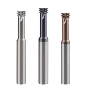
Qualifying a thread mill manufacturer for HRC 60–65 tooling demands far more than verifying whether a cutter can physically make a thread. In production environments, the real test is whether the vendor can repeat that exact tool performance lot after lot. When supporting precision shops across North America and Europe, we vet trial cut logs, cutting edge prep, and grind consistency rather than catalog claims.
Before contacting a tooling vendor, define your exact production parameters rather than asking a generic question like “Can this tool cut HRC 65?” Provide your alloy grade, verified Rockwell hardness, thread pitch, minor hole diameter, and toolholder type. A qualified manufacturer uses this operational data to engineer a rigid cutter body, specify the right micro-geometry, and guarantee seamless scaling from prototype to production.
Technical Parameters and Machining Data We Confirm with Thread Mill Manufacturers
When evaluating specialized suppliers, we drill into the micro-grain carbide substrate, flute web thickness, coating adhesion, and micro-hone specs. For HRC 60–65 tool steels, generic assurances that a tool is “hard-steel ready” are meaningless. We demand documented proof of the exact speeds, feeds, radial stepovers, and internal thread tolerances held in comparable high-hardness test cuts.
A reputable thread mill manufacturer should readily provide full application logs for their test data. Confirm workpiece material, Rockwell C hardness, gauge length, machine spindle dynamics, toolholder style, and go/no-go gauge pass rates. If a supplier cannot share verifiable cut conditions, their published tool life estimates provide zero baseline value for high-volume manufacturing.
How to Request Actual Test Conditions from Suppliers for HRC 60–65 Hardened Steel
To validate hardened steel threading tools, insist that supplier test cuts mirror your exact shop-floor setup. If your job involves blind M6 threads in HRC 62 D2 steel at 2.5xD, test data from shallow M10 holes in softer material is completely useless. Shifting from shallow to deep threads drastically increases deflection and changes chip evacuation dynamics.
When vetting an HRC65 thread mill, require the supplier to certify actual workpiece hardness via hardness testing instead of just quoting the raw stock grade. Compare their machine rigidity, coolant blast, stickout, and tool runout against your CNC setup. Correlating these variables upfront prevents chasing ghost issues once the tooling hits your spindle.
Assessing Manufacturing Capability: From Tool Consistency and Dimensional Tolerances to Batch Stability
A flawless single-tool trial only proves cutting feasibility—it does not prove batch consistency. In volume manufacturing, we audit flute runout, web thickness, OD grinding tolerances, and edge hone repeatability across multiple production runs. On sub-M6 cutters, a five-micron variance in core thickness significantly changes tool stiffness, causing unpredictable cutting deflection and pitch gauge binding.
Audit the performance of subsequent tooling lots, particularly batches two and three. If thread tolerances or tool wear fluctuate on the same job with identical CNC programs, look for variations in carbide batches, edge prep, or PVD coating adhesion. A world-class thread mill manufacturer must guarantee repeatable tool geometry, grinding tolerances, and tool life across every single shipment.
How We Match HRC65 Thread Mills to Specific Machining Conditions for European and American Clients
For our precision clients in Europe and the US, we never recommend an off-the-shelf HRC65 thread mill in a vacuum. We reverse-engineer the tooling package from the part print, evaluating thread pitch, full depth, bore tolerances, machine taper, and toolholding systems. Then, we formulate the carbide substrate, edge prep hone, PVD coating, and radial stepover strategy to maximize process stability.
If you are threading SKD11, D2, or hardened mold components from HRC 60 to 65, send us your part drawings, material certs, and current setup parameters. Our engineering team will analyze your cutting loads, tool overhang, and cycle requirements to eliminate chipping and dimensional drift. Finding the right solution is never about hunting for a magic catalog tool; it is about engineering a repeatable machining process for your shop.