



We previously solved a challenging job for a client machining internal threads into heat-treated mold steel at HRC 60. While the thread profile was standard, a small bore diameter, deep thread engagement, and tight batch tolerances pushed the limits. Single-part trials ran fine, but serial production triggered premature flank wear and micro-chipping, causing pitch diameter drift. The real hurdle was not just making one thread, but engineering a stable, repeatable thread milling hardened steel process.
We see this scenario frequently in high-hardness mold and die production. When thread milling HRC60 steel, substrate grain size, cutting edge prep, coating adhesion, radial runout, and machine rigidity must align perfectly. Neglecting even one variable leads to thread pitch errors, poor surface finish, or catastrophic tool failure mid-cycle. Catalog hardness ratings never tell the full story; we always engineer the setup around true material structure, bore depth, and dynamic machine stiffness.
For materials in the HRC 60–62 range, we specify micro-grain solid carbide thread mills engineered with reinforced core diameters. Tool geometry, helix angle, and AlTiN or TiAlSiN are tailored specifically to the alloy, such as D2 or SKD11. Furthermore, thread milling speeds and feeds cannot follow conventional steel charts. Optimizing surface footage, radial chip thinning, and climbing helical toolpaths directly dictates cutting edge longevity and thermal stability.
Maintaining a tight thread milling tolerance across long production runs remains the true test of process control. We often diagnose jobs where the tool survives, yet threads fail go/no-go gauging after several dozen cycles due to tool deflection and thermal growth. Eliminating these drifts requires heat-shrink or hydraulic toolholders, sub-micron runout verification, and precise radial wear compensation. A process is only viable if it reliably holds thread class limits from the first part to the last.
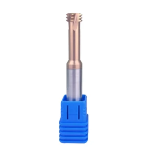
Thread Milling HRC60 Steel – Determining Suitability for Thread Milling
When assessing suitability for thread milling HRC60 steel, we never rely on catalog hardness ratings alone. We first examine heat treatment uniformity, effective thread depth, and machine tool rigidity. Parts at HRC 60 can behave completely differently depending on core hardness and microstructure.
The toughest challenges occur when small bore diameters, deep holes, and high hardness converge. Small threads restrict the tool shank diameter, while deep engagement amplifies overhang deflection and vibration. For reliable thread milling hardened steel, you must evaluate toolholder balance, spindle runout, and part fixturing together.
Assessing Machining Difficulty Based on Actual Hardness, Material Condition, and Thread Specifications
We always measure the actual hardness on the shop floor rather than trusting raw material certs. Shifting from HRC 58 to HRC 61 dramatically spikes radial cutting forces and accelerates flank wear. We evaluate hole depth, pitch, and pre-drilled bore quality to determine the tool overhang ratio.
During pilot runs, a single good thread does not guarantee long-term process capability. We track acoustic harmonics, edge micro-fractures, and surface finish across dozens of continuous cycles. For tight thread milling tolerance control in hard materials, batch stability matters far more than first-piece buy-off.
Key Factors We Consider When Selecting Thread Mills for HRC60–62 Hardened Steel
Selecting cutters for HRC 60–62 steel demands looking past generic catalog claims like “rated up to HRC 65.” We inspect the effective flute length, core reinforcement, edge honing radius, and PVD coating adhesion. In deep, small-diameter bores, an overbuilt tool profile can restrict chip evacuation and cause catastrophic chipping.
Production volume also dictates tooling grade and operational geometry. Prototyping allows conservative cycle times, whereas high-volume production demands predictable tool wear curves without dimensional drift. When choosing thread mills for HRC60 steel, we balance substrate toughness with operational wear rates.
Determining Specifications Based on Hole Diameter, Pitch, Thread Depth, and Machining Allowance
We establish tool geometry by reverse-engineering the pre-machined minor diameter and thread pitch. The bore size sets the maximum tool diameter, while thread depth dictates required neck relief. For small-diameter internal threads, selecting the proper thread milling speeds and feeds prevents tool deflection and pitch diameter taper.
Stock allowance inside the pre-drilled hole is equally vital for process reliability. Leaving too much material overloads individual cutting teeth, while leaving too little leads to tool rubbing and work hardening. We match the tool profile directly to pilot hole accuracy to avoid premature edge failure.
Why We Prioritize Solid Carbide Thread Mills for Machining HRC60 Hardened Steel
Hardened mold steels demand the extreme modulus of elasticity found only in ultra-fine submicron carbide. We prioritize solid carbide thread mills to resist intense deflection forces and deliver high thermal stability. However, carbide alone is not enough; edge prep, high-heat coatings, and short overhangs remain essential.
Even premium carbide fails rapidly if total radial runout exceeds 0.005 mm (0.0002 in) at the tip. We pair these tools with hydraulic or shrink-fit chucks to ensure balanced chip loads on every flute. In extreme hardness applications, rigid tool clamping is what turns a brittle cutting edge into a reliable production solution.
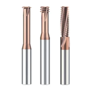
Thread Mills for HRC60 Steel: Key Parameters to Consider When Selecting Solid Carbide Thread Mills
When choosing cutters for extreme-hardness applications, catalog ratings rarely reveal the entire picture. On an HRC 60 mold steel project, initial parts passed inspection, but continuous runs triggered premature edge wear and pitch diameter drift. Real-world performance depends heavily on core diameter, flute relief, coating adhesion, and total overhang. Selecting thread mills for HRC60 steel requires evaluating tool geometry alongside real spindle conditions.
For high-hardness alloys, we reverse-engineer the tool structure directly from the hole depth and thread pitch. In small-diameter, deep-hole setups, tool deflection and clamping rigidity directly compete with cutting forces. We run monitored test cuts to evaluate edge fatigue and pitch stability before finalizing geometry. This upfront verification prevents costly scrap and ensures dependable thread milling hardened steel operations.
How We Select Solid Carbide Thread Mills for HRC60 Steel
We evaluate the micro-grain carbide substrate, edge prep, and shank rigidity to ensure edge durability. In hard materials, microscopic chipping rapidly degrades thread profiles and leads to binding or thread galling. The objective is not merely choosing the hardest grade, but finding a tough, balanced substrate that withstands severe cyclic impact.
Machine dynamics and toolholder interfaces also dictate cutting performance. High spindle runout or excessive projection will ruin an otherwise premium cutter before completing a single batch. We always inspect toolholder TIR and machine stiffness to maximize solid carbide thread mills reliability. A viable cutter must deliver dependable tool life across full shifts, not just first-article trials.
Selecting Tool Diameter and Effective Cutting Length Based on Thread Diameter, Pitch, and Thread Depth
Tool dimensions must leave adequate clearance inside the minor bore for smooth helical interpolation without tool rubbing. While small bores restrict the cutter shank diameter, deep threads force longer tool extensions that increase the risk of chatter. Balancing tool core thickness with necessary chip clearance is essential for process stability.
Excessive tool projection drastically lowers system rigidity and amplifies deflection under heavy radial loads. Never run extra flute length or excessive neck extension unless the thread depth strictly demands it. Tuning your thread milling speeds and feeds to the actual tool projection prevents pitch diameter taper in high-aspect-ratio holes.
Comparing the Impact of Flute Count, Helix Angle, and Cutting Edge Geometry on HRC60 Machining
More flutes increase metal removal rates, but they also reduce flute valley volume and chip clearance. When cutting hardened steel, fine chips must evacuate cleanly to prevent re-cutting and catastrophic tooth breakage. We balance flute count against core web thickness to guarantee maximum resistance against radial bending forces.
Helix angles and negative rake edge hones control cutting edge entry and thermal load distribution. A tailored edge prep protects the fragile cutting crest from micro-chipping without creating excessive tool pressure. Dialing in edge micro-geometry helps maintain tight thread milling tolerance standards without generating harmonic chatter.
Selecting Carbide Grades and Coatings Based on Wear Patterns in HRC60 Hardened Steel
We select tool coatings by diagnosing specific wear mechanics under a microscope rather than following generic charts. We inspect cutting edges for normal abrasive flank wear, thermal cracking, chemical degradation, or chipping. Identifying the exact failure mode lets us target the root cause directly on the machine.
If thread pitch drifts while the cutting edge remains intact, we adjust thermal compensation or radial wear offsets first. When severe edge chipping occurs, the problem usually stems from excessive tool runout or improper edge conditioning. Matching the coating, substrate toughness, and thread milling HRC60 steel parameters creates an exceptionally robust, wear-resistant machining process.
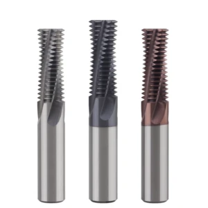
Thread Milling Speeds and Feeds for HRC60 Steel: Setting Actual Machining Parameters
Manufacturer catalog charts provide baseline reference numbers, not production-ready setups. On an HRC 60 mold job, recommended feeds and speeds passed initial inspection but caused micro-chipping during serial runs. Actual cutting loads depend heavily on cutter diameter, effective overhang, core web thickness, and machine rigidity. Optimizing thread milling speeds and feeds requires testing cutting harmonics, spindle draw, and flank wear before running high-volume jobs.
When cutting materials in the HRC 60–62 range, establish a conservative starting baseline and scale up incrementally. Deep-hole applications and small thread profiles amplify bending forces and chip-re-cutting risks. Fine-tuning radial step-over alongside programming helical climbing paths prevents edge fracture. This dialed-in methodology ensures predictable, long-term success during thread milling hardened steel operations.
Determining Speeds and Feeds Based on Tool Diameter and HRC60 Hardness
Tool diameter determines both surface footage and radial core deflection under cut. Hardness spikes from HRC 58 to HRC 61 dramatically intensify friction and thermal loads on the cutting crests. Smaller cutters have lower core rigidity and require reduced surface speeds to counter premature thermal breakdown. We establish safe baselines by balancing pitch requirements against cutter diameter and dynamic machine rigidity.
Small-diameter cutters demand extra scrutiny because minor runout drastically increases tooth loading. We assess cutting harmonics, machine spindle load, and part finish on the first few workpieces. If the cutting edge remains clean and sharp without signs of micro-fracturing, we gradually increase feed per tooth. Carefully setting parameters for thread milling HRC60 steel avoids sudden edge breakage and preserves hole quality.
How We Adjust Thread Milling RPM, Feed Rate, and Feed per Tooth
Spindle speed must be calculated strictly from actual surface footage (SFM), not arbitrary machine maximums. Feed rate should reflect true chip thickness, especially when programming internal helical arcs where the tool path radius differs from the hole radius. In high-hardness alloys, overfeeding creates tool deflection, while underfeeding leads to tool rubbing and work hardening.
We treat rotational speed and feed per tooth as an integrated balance. When tool life is short, we first verify radial runout, tool projection, and workholding rigidity before adjusting table feeds. We only increase feed per tooth after verifying tool flank wear and pitch consistency. This discipline ensures solid carbide thread mills deliver reliable cycle times and maximum tool life.
How We Control Single-Pass Cutting Load Based on Radial Engagement and Thread Depth
Radial depth of cut dictates instantaneous cutting pressure on each thread tooth. For deep threads in hardened steel, taking the full thread profile in a single pass overloads the cutter and causes tool deflection. We divide thread profiles into multiple radial passes to control tool deflection and maintain straight thread walls.
On a deep-hole mold project, single-pass cuts caused rapid tool wear and thread taper. Splitting the cycle into three radial passes eliminated harmonic chatter and stabilized the process. When setting radial engagement, always evaluate bore depth, tool reach, and spindle taper rigidity together. A multi-pass strategy provides the stability needed to protect critical thread mills for HRC60 steel.
How We Adjust Thread Milling Speeds and Feeds Based on Test Cut Results Instead of Relying Solely on Catalog Data
We use initial test cuts to determine the real-world operating window of the machine-tool setup. After machining the first part, we inspect the thread with pitch micrometers and examine the cutting edges under magnification. Passing thread gauge checks is not enough; any micro-chipping on the teeth will cause rapid dimensional failure during continuous runs.
If the cutting edge remains undamaged and the thread finish is clean, we increase feeds or speeds in small steps. We adjust only one cutting variable at a time while tracking part counts and tool wear progression. This data-driven approach guarantees repeatable thread milling tolerance control throughout long production shifts.
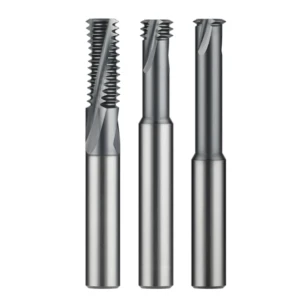
Thread Milling Tolerance – Controlling Thread Dimensions and Precision in HRC60 Steel
A common challenge in production is seeing the first piece pass inspection, only for dimensions to drift after fifty cycles. Swapping out the cutter rarely solves the underlying problem. Pitch diameter stability relies on a synchronized system: tool deflection, cutter wear offsets, spindle runout, and edge micro-chipping. Consistently holding a tight thread milling tolerance in high-hardness steel requires managing all of these machining variables together.
Never evaluate precision using isolated first-article parts. We compare early workpieces against mid-batch and end-of-run parts to identify the root cause of dimensional shifts. Small-diameter and deep-thread applications in the HRC 60–62 range leave very little room for error. Isolating thermal expansion and mechanical deflection is essential for repeatable thread milling hardened steel operations.
Controlling Thread Milling Tolerance via Toolpath Strategy
Toolpath design directly dictates cutting pressure during helical interpolation. We always program smooth tangential arc-in and arc-out entries to prevent dwell marks and localized pitch distortion. Climb milling is mandatory to produce thinning chips, keeping cutting heat focused inside the chip rather than transferring into the fragile workpiece threads.
High-precision threads in hard steel should never be cut to final size in a single pass. Splitting the operation into roughing passes and a dedicated spring pass eliminates deflection-induced pitch taper. Stabilizing the toolpath geometry first allows for predictable diameter offsets. This structured programming method ensures dependable results during thread milling HRC60 steel.
Adjusting Tool Compensation and Finishing Passes Based on Actual Thread Dimensions
We base CNC wear offset adjustments on physical thread measurements, not on theoretical CAD models. We check pitch diameters using calibrated three-wire systems or pitch micrometers alongside optical thread profile inspections. If thread dimensions shift slightly while the cutting teeth remain sharp, adjusting radial wear compensation is far better than prematurely swapping cutters.
On tight-tolerance molds, a dedicated finishing pass cleans up material pushed aside by tool pressure. This secondary cleanup pass removes nominal stock, establishing consistent surface quality and accurate pitch geometry across long production runs. Pairing proper offset tracking with rigid solid carbide thread mills guarantees continuous part-to-part repeatability.
Assessing the Impact of Thread Mill Runout on Dimensional Stability
Total indicated runout (TIR) is the most common cause of premature tool wear and pitch diameter errors. We measure runout across the spindle taper, toolholder bore, and tool shank—never just at the tool flutes. Runout exceeding 0.005 mm (0.0002 in) concentrates the entire cut on a single tooth, leading to rapid chipping and oversize threads.
Small-diameter cutters are especially sensitive to runout variations. Contamination inside a collet or improper clamping torque can double runout readings and cause inconsistent pitch sizing between tool changes. Before changing programmed thread milling speeds and feeds, always clean the holder mating tapers and confirm toolholder TIR.
Addressing Gradual Dimensional Shifts During HRC60 Thread Milling
When thread sizes begin drifting, track the dimensional trend across sequential parts before changing offsets. Steady, predictable drift paired with even flank wear indicates normal cutting edge consumption. In contrast, erratic, scattered dimensional changes usually point to loose part clamping, thermal machine growth, or erratic tool deflection.
If pitch diameters gradually close up on internal threads, the cutting edge is wearing down and requires radial compensation. If dimensions spike unexpectedly, inspect the cutter teeth for micro-chipping or loose collet grips. Identifying the failure mechanism helps you deploy the right thread mills for HRC60 steel and establish reliable, long-term process capability.
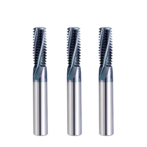
Thread Mill Runout and Machine Rigidity: Solving Chipping, Chatter Marks, and Tool Breakage in HRC60 Machining
Operators often assume aggressive feeds cause catastrophic tool breakage, even when cutting parameters are well within catalog limits. On-site audits usually reveal that excessive dynamic runout, poor toolholder seating, or unsupported tool overhang are the true culprits. Extreme-hardness steels do not tolerate uneven chip loads; a fraction of an off-center tooth bears the entire impact force, causing instantaneous edge fracture.
Before launching serial runs, always inspect toolholder cleanliness, spindle taper contact, and dynamic radial runout. Adjusting programmed spindle speeds will never fix an unstable mechanical setup. In deep-hole applications, stabilizing the entire machine-spindle-holder-workpiece system is mandatory. Establishing baseline mechanical rigidity is the foundation for successful thread milling hardened steel operations.
Why We Prioritize Checking Thread Mill Runout Before Machining HRC60 Steel
Total indicated runout directly dictates tooth load balance on small-diameter cutters. We always indicate the tool tip after tightening the assembly in the holder, never relying on off-machine presetter measurements alone. Radial runout exceeding 0.005 mm (0.0002 in) concentrates the full chip load onto a single flute, triggering immediate micro-chipping.
On an HRC 60 mold core job, erratic cutter life plagued production despite identical speeds and feeds across shifts. Inspecting the toolholders revealed erratic clamping runout between setup technicians. Once we standardized heat-shrink toolholders with sub-micron runout, edge wear evened out across all flutes. Verifying dynamic runout is the first step when optimizing thread milling HRC60 steel processes.
How We Troubleshoot Runout Caused by Holders, Spindles, and Tool Clamping
We isolate runout issues by working outward from the cutting tool to the machine spindle. First, clean the cutter shank with solvent to check for burrs, fretting, or micron-level gouges. Next, check the toolholder taper using contact bluing, and finally inspect the spindle taper for debris or bell-mouthing. This systematic diagnostic process isolates mechanical errors without guesswork.
Clamping length and stick-out distance require strict control in high-hardness steels. Excessive projection turns minimal gauge-line runout into severe cutting-zone whip under heavy radial loads. We choke up on the cutter shank to minimize unnecessary reach before running test cuts. Rigorous mechanical verification maximizes the service life of solid carbide thread mills.
How We Reduce Chatter by Addressing Machine Rigidity, Tool Overhang, and Clamping Methods
Chatter marks on thread flanks point to systemic resonance, not just incorrect surface footage. Unsupported thin-wall workpieces, flimsy vise setups, excessive tool overhang, and worn spindle bearings generate cyclic vibration during helical interpolation. Long-reach cutters amplify harmonic chatter, rapidly ruining surface finish and rounding thread crests.
We suppress chatter by shortening tool extension and strengthening workpiece fixturing. Switching from ER collet chucks to high-dampening hydraulic chucks or rigid shrink-fit systems absorbs cutting harmonics effectively. Upgrading machine and fixturing stiffness ensures dependable thread milling tolerance control throughout intense production cycles.
How We Systematically Troubleshoot Chipping on Thread Mills Used in HRC60 Hardened Steel
When cutting teeth chip, preserve the damaged tool for optical microscope inspection before scrapping it. Inspect whether fractures occur at the crest, radial flank, or entry flute to determine if failure happened during lead-in, steady interpolation, or retract. Concentrated wear on one flute indicates severe tool runout or asymmetric tool deflection.
Our root-cause troubleshooting sequence follows a strict hierarchy: tool runout → setup rigidity → tool overhang → cutting strategy → radial step-over. When micro-chipping persists under conservative parameters, reducing radial pass depth or adjusting thread milling speeds and feeds resolves the shock load. Addressing root mechanical causes ensures dependable performance from specialized thread mills for HRC60 steel.
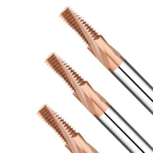
Carbide Thread Mill Tool Life – Maximizing Tool Life in HRC60 Hardened Steel
Raw part counts should never serve as the sole benchmark for tool life. In high-hardness production, identical cutters running the same heat-treated material can show wildly different tool longevity across different machine centers. A cutter may look intact under naked-eye inspection, yet it may already be pushing pitch diameters out of specification. Maximizing true carbide thread mill tool life means tracking how many holes a cutter completes while holding strict drawing tolerances and thread flank finishes.
Evaluating tool durability in HRC 60–62 steel requires continuous tracking of spindle load draw, acoustic pitch, and flank wear land growth. Waiting for a cutter to catastrophically snap before changing it is a costly mistake that ruins valuable mold components. Monitoring progressive abrasive wear patterns prevents premature tool changes while eliminating out-of-spec scrap. This disciplined tracking is crucial when running precision thread milling hardened steel operations.
Determining the Optimal Point for Carbide Thread Mill Replacement
Predictable tool change intervals rely on empirical measurement data rather than theoretical catalog cycles. On tight-tolerance jobs, we verify pitch diameters on the first part, midway through production, and near the projected wear limit. If pitch diameters begin drifting out of drawing limits, change the tool immediately—even if the cutting edges show no visible chips.
We base tool change decisions on dimensional repeatability, cutting edge condition, and total thread count. Squeezing a few extra parts out of a dull cutter in HRC 60 steel inevitably leads to high scrap rates and costly machine downtime. Proactively retiring worn cutters protects expensive workpieces and preserves tight thread milling tolerance standards across long unattended shifts.
Controlling Tool Wear via Cutting Speed, Feed Rate, and Radial Engagement
Surface footage directly controls cutting zone temperatures and thermal stress on the cutting edge. Machining high-hardness steel demands exceptional thermal resistance, where excessive RPM causes rapid coating breakdown, and overly conservative feeds induce rubbing and work hardening. Establishing a balanced cutting baseline first allows incremental parameter optimization based on actual wear scars.
Radial step-over depth must be controlled with equal precision. High radial engagement creates massive impact spikes on each tooth entry, causing rapid micro-fractures on fragile cutting edges. We adjust one parameter at a time while logging part counts and flank wear progression to identify root causes. Fine-tuning these variables ensures thread mills for HRC60 steel achieve predictable, cost-effective tool life.
Distinguishing Between Normal Flank Wear, Micro-chipping, and Sudden Tool Breakage
Diagnosing wear morphology under an optical microscope reveals the true physical cutting conditions. Uniform, gradual flank wear indicates a stable cutting process where tool offsets can safely compensate for minor size loss. In contrast, jagged micro-chipping along the cutting edge signals excessive radial shock, improper tool entry, or dynamic runout that immediately compromises thread quality.
Catastrophic tool fractures demand immediate analysis of the broken shank to locate the initial failure point. Recurring breaks at the same flute location point directly to excessive radial loads, long tool overhang, or severe harmonic vibration. Identifying whether a failure stems from thermal breakdown or mechanical impact protects your solid carbide thread mills during demanding production cycles.
Evaluating Thread Mill Tool Life Based on Part Count, Thread Tolerance, and Edge Condition
We log production data across multiple batches: total holes threaded per tool, thread gauge fit frequency, and surface finish changes. Aggregating these real-world metrics establishes a reliable tool retirement window far superior to single-part test cuts. This data-driven strategy eliminates guesswork and stabilizes tool replacement schedules.
A cutter that holds pitch limits for eighty parts before drifting gives you a clear threshold for setting an automated tool life counter at seventy-five parts. Part count serves merely as an operational tracking metric; actual thread form, surface finish, and edge integrity make the final call. Balancing tool wear limits with dialed-in thread milling speeds and feeds guarantees dependable, zero-defect production in thread milling HRC60 steel.
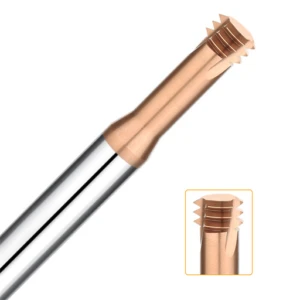
Thread Milling Hardened Steel – Solving Common Thread Quality Issues in HRC60 Steel
Machining threads in HRC 60 steel rarely fails because the cutter cannot cut; issues appear gradually through chatter, thread pitch taper, micro-burrs, or mid-cycle breakage. Small-diameter, deep-hole setups amplify the slightest process deviation into batch-wide defects. Rather than randomly tweaking feed rates, we troubleshoot the cutter geometry, toolpath strategy, clamping rigidity, and machine mechanics as a unified system.
We isolate defects by determining the exact cycle phase where failure occurs: entry impact, steady helical interpolation, or tool retraction. We then evaluate thread profile integrity, surface finish, and cutting edge wear under magnification. This disciplined root-cause analysis is the most reliable way to achieve stable, high-yield results during thread milling hardened steel operations.
Solving Chatter and Poor Surface Finish in HRC60 Steel Thread Milling
When chatter marks appear on thread flanks, look past the cutter itself and inspect the dynamic mechanical setup. Measure gauge-line toolholder runout, cutter extension, and part clamping stiffness, while listening for harmonic vibration. If the cutting teeth remain unchipped but threads show cyclic chatter, the issue almost always stems from insufficient system rigidity.
To eliminate chatter, choke up on tool overhang and divide the thread profile into multiple light radial passes. Never alter feeds, speeds, and depths simultaneously; reduce the radial step-over first to lower instantaneous cutting pressures. Checking thread surface finish after each controlled step confirms whether harmonics have been eliminated in thread milling HRC60 steel.
How We Address Incomplete Thread Profiles, Dimensional Drift, and Burrs
Incomplete thread forms usually stem from incorrect pre-drilled bore dimensions or excessive radial tool deflection under load. If thread crests or roots miss specification, inspect the cutting teeth under high magnification for micro-chipping or abrasive flank wear. Even slight edge deterioration alters the cutting profile and causes thread gauge binding, even when program coordinates remain untouched.
Gradual pitch drift requires comparing initial parts against late-batch components to calculate actual carbide wear rates. Burrs at the thread entry or exit typically point to a dulling cutter or an unchamfered bore. Resolving profile and burr defects requires fine-tuning radial finish passes and wear offsets to maintain an uncompromising thread milling tolerance.
How We Resolve Thread Mill Breakage in Small-Diameter, Deep-Thread Applications
Small-diameter cutters running in deep bores face severe deflection risks due to their slender core web geometry. High overhang-to-diameter ratios amplify spindle runout and cyclic bending loads under cut. Taking an aggressive radial step-over in deep holes introduces sudden shock loads during helical moves, causing instant tool breakage.
Preventing tool failure begins by minimizing projection length and running high-rigidity hydraulic or shrink-fit holders. If a tool snaps at a specific hole depth, inspect the bore for chip packing, taper error, or work hardening from the drill. Lowering spindle RPM rarely fixes breakage; instead, programming smooth tangential lead-ins protects fragile solid carbide thread mills.
How We Troubleshoot Unstable Machining Results (HRC 60–62) Across Four Key Areas: Tools, Parameters, Tool Paths, and Machine Tools
When machining high-hardness alloys becomes erratic, we follow a strict four-pillar diagnostic sequence. First, examine cutting edge wear, runout, and substrate integrity; second, review cutting speeds, chip loads, and radial step-overs; third, audit lead-in arc geometry and finishing spring passes; fourth, verify spindle taper cleanliness and fixture rigidity. Isolating these factors one at a time prevents compounding errors.
Shop-floor troubleshooting often reveals that programming is sound, but mechanical errors are quietly degrading the cut. Excessive toolholder runout or long tool extensions often cause premature wear that gets misdiagnosed as bad code. Pairing stable machine dynamics with optimized thread milling speeds and feeds delivers predictable tool life and process capability when deploying specialized thread mills for HRC60 steel.
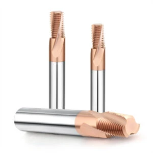
Custom Thread Mill Manufacturer – How We Validate Tooling Solutions for HRC 60–65 Hardened Steel
Machining HRC 60–65 alloys requires engineering every interface rather than relying on a single catalog parameter. In high-aspect bores, a first article may pass inspection while subsequent parts drift rapidly out of gauge. As an engineering-driven manufacturer, we design tooling backward from actual spindle stiffness, bore depth, and dynamic runout. Developing a dependable custom thread mill eliminates the cycle-time and dimensional risks inherent to extreme-hardness threading.
We require comprehensive shop-floor data—including pre-drilled bore tolerance, thermal treatment history, and toolholder interface—before proposing a tooling solution. Catalog tools frequently fail in deep holes because standard geometries lack sufficient core web thickness. Grounded in decades of production experience, our technical evaluations prioritize process repeatability over standard off-the-shelf catalog claims for thread milling hardened steel.
How We Design Solid Carbide Thread Mills Based on Customer Conditions
Every custom design begins with the physical constraints of the pre-machined hole and thread specification. We analyze thread depth, pitch, and minor bore diameter to determine optimal neck relief, flute count, and core web reinforcement. In miniature bores, uncontrolled runout rapidly leads to micro-chipping, making structural rigidity our top priority during cutter development.
Stating material hardness as simply “HRC 65” overlooks critical alloy variations across D2, CPM-10V, or tungsten-carbide grades. We factor in spindle taper class, hydraulic or heat-shrink toolholding, and coolant delivery to optimize substrate selection. Tailoring submicron grain matrices and high-heat coatings ensures our solid carbide thread mills resist thermal fatigue and edge micro-fracture during production.
Adjusting Tool Geometry Based on HRC 60–65 Hardness, Thread Size, Pitch, and Thread Depth
Thread pitch dictates instantaneous tooth contact area, while thread depth controls required tool reach. Long-reach tools demand reinforced transition necks and variable helix designs to disrupt harmonic resonance and reduce cutting deflection. Modifying cutting edge prep with protective negative hone angles preserves the crest from brittle failure in HRC 60–65 materials.
When chipping or vibration occurs at specific bore depths, the failure usually stems from restricted chip evacuation or localized resonance. Re-engineering flute core tapers and relief angles provides clearance for fine, work-hardened chips. Deploying application-specific geometries within dedicated thread mills for HRC60 steel prevents localized tool binding and edge fracture.
Validating Thread Mill Speeds and Feeds, Thread Milling Tolerances, and Tool Life Through Test Cuts
First-article trial cuts serve to map the actual operating envelope of the machine setup. After cutting the first thread, we inspect pitch profile form, flank roughness, and cutting edge wear under magnification. If pitch diameters begin drifting after several dozen cycles, we isolate radial tool deflection and thermal runout before adjusting offsets.
Validating an extreme-hardness threading application requires balancing cutting parameters with repeatable part yields. When micro-chipping occurs under conservative parameters, reducing radial step-over or programming climbing entries prevents premature edge failure. Setting verified thread milling speeds and feeds guarantees that parts maintain a tight thread milling tolerance across the tool’s entire service life.
How We Provide Technical Support to European and American Machining Clients—From Standard to Custom Thread Mills
Western manufacturing facilities often struggle with standard catalog tooling when machining high-hardness die inserts. While catalog cutters handle shallow, open setups, deep internal threads demand optimized flute lengths and specialized PVD coatings. We audit your drawings and machine kinematics to determine whether an off-the-shelf cutter works or if a custom design is required.
If you experience edge chipping, thread taper, or erratic cutter life in high-hardness steel, our engineering team provides direct root-cause troubleshooting. We review your toolholder runout, programmed toolpaths, and part rigidity to optimize cutting performance. Through comprehensive data analysis, we engineer carbide thread mill tool life solutions that deliver zero-defect results for thread milling HRC60 steel.






