
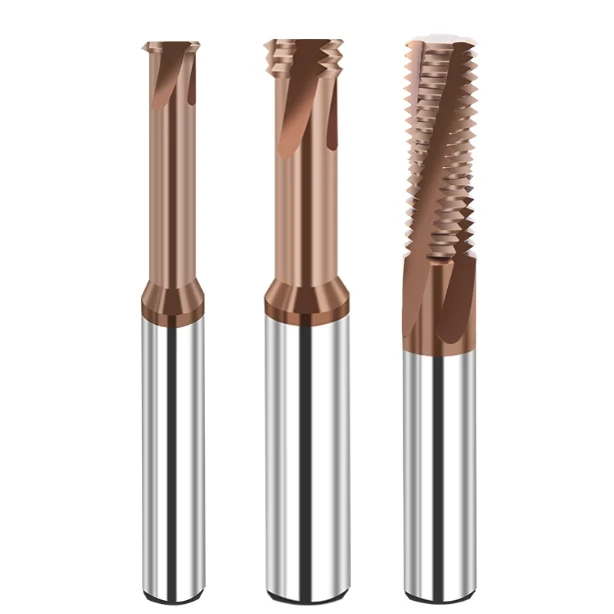
If your line runs high-value parts like hydraulic blocks or stainless housings, thread inspection failures rarely cause the biggest headache. The real killer is the stubborn metal collar clinging to the hole entry and exit.
Our team saw this firsthand during an audit for a Tier 1 automotive supplier. Secondary burrs in threaded ports completely paralyzed an automated cycle. Operators had to stop spindles and scrape holes by hand under magnification, driving scrap rates through the roof. The shop’s quick fix was “throw in a new cutter.” Yet even with a fresh tool, the same flaring came back in under twenty parts.
This is not an isolated breakdown. Over sixteen years of troubleshooting on the floor, we have treated thread mill burr issues as a persistent enemy on titanium, tool steels, and austenitic stainless.
Burrs form when cutting forces overpower material yield limits. Issues like entry collars, crest tearing, and material smearing from early thread mill tool wear cannot be pinned on one single setting. Poor evacuation, harmonic chatter, aggressive lead-ins, or edge loss quickly destroy shear balance, turning clean cutting into dull plowing. True thread milling burr prevention requires tuning entry angles, substrate stiffness, and pilot chamfer timing—not burning margin on tedious manual thread burr removal.
Does this sound familiar? Your pitch diameter gauge glides right through, yet that razor-thin curled edge persists around the entrance, forcing operators to drop feeds or stop for rework.

Common Thread Milling Burr Morphologies on the Shop Floor: An Analysis of Causes at Entry/Exit Points and Thread Crests
When parts get red-tagged on the inspection table, shop operators often call every defect a burr. That general label stalls root-cause analysis. In our field experience, thread milling burrs split into two distinct shapes: thick rolled rims at hole edges and torn, sawtooth fringes along the thread crests. You cannot fix the issue by randomly tweaking feed rates or replacing tools until you identify the exact defect shape.
Metal does not simply slice away cleanly; it shears and plastically deforms before it separates. When cutting forces overcome the support of the parent material at a free edge, metal flows toward the path of least resistance. Through our tests on high-pressure manifolds, we see very different mechanical loads at the hole shoulders compared to the flanks. Each zone demands its own troubleshooting fix.
Thread Entrance Burrs: Helical Entry Angles and Pilot Hole Chamfers
If you feel sharp metal rollover on the first incomplete thread crest, you are dealing with thread entrance burrs. This usually happens when CAM posts default to a direct linear plunge or a tiny radial lead-in. The cutting edge bites into the wall with an instantaneous spike in chip thickness. Before the tool can form a true chip, its flank face plows the thin rim right out of the hole face.
This defect usually comes down to an improper process sequence. To shave cycle time, shops often skip the pre-chamfer or push it after the threading pass. Our test runs show that chamfering before threading provides a clean lead-in bevel that absorbs cutting forces. If your spindle rigidity is limited, program a 90-degree or 180-degree smooth arc-in with a matched axial pitch climb. That extra second in cycle time saves minutes of manual deburring later.
Thread Crest Burrs and Residue: Climb Milling vs Conventional Milling Paths
A worse problem on assembly lines is internal thread flank binding. When bolts gall during torquing, look for thread mill tool wear and micro-burrs lining the helical crests. In modern CNC programming, climb milling is the standard rule because it thins the chip from thick to zero. However, when the finish chip thins past the honed cutting edge radius, cutting ceases. The tool tip simply smears hot metal toward the crest tips.
When working with ductile stainless alloys, we sometimes make a counterintuitive switch to a light conventional cleanup pass. Conventional milling starts at zero chip thickness and cuts outward under tensile stress, which can cleanly shear off smeared foil edges. This choice depends on your setup: climb milling protects tool life, while a conventional spring pass cleans up ductile workpieces if the machine setup is rigid.

Tool Wear and Overhang Limits: How Thread Mill Wear Directly Triggers Burrs
In high-volume shops, operators often push cutting tools until parts fail thread gauge inspection. Our field data shows that hole-edge rollover spikes long before pitch diameters drift out of tolerance. Progressive thread mill tool wear alters microscopic edge hone geometry, turning clean shear lines into crushing zones. Once compressive forces exceed material yield limits, hot metal extrudes outward and creates heavy burrs.
Squeezing extra parts out of worn cutters is a false economy. Heavy flank wear degrades hole wall micro-finish and scatters bolt torque specs across the batch. To stop manual deburring from draining shop profits, technicians must track tool life against burr formation rather than spindle-load spikes alone.
Flank Wear and Edge Dulling: Extrusion and Friction Replace Shearing
Inspect a worn cutter under a shop microscope, and you will see the edge radius expand from 4 µm to over 30 µm. This micro-level breakdown is the primary cause of every stubborn thread burr. When edge roundness exceeds undeformed chip thickness, the tool stops shearing and starts plowing. Material squirts laterally around the tool flanks, leaving heavy flash across the roots and crests.
When milling 316 stainless flanges, do not wait for flank wear to reach the general milling limit of 0.2 mm. In precision threading, wear scars past 0.06 mm generate severe frictional heat that work-hardens the cut zone. That heat welds micro-chips back onto the profile. Index or swap cutters before shearing degrades into plowing to keep cleanup costs at zero.
Insufficient Rigidity in Long-Overhang Setups: Micro-Vibration Burrs in Deep Holes
Deep-cavity manifolds and mold cooling channels often force length-to-diameter ratios beyond 3:1 or 4:1. Running a long-reach threaded end mill under these conditions produces fine, feathery fringes even with razor-sharp edges. The culprit is dynamic deflection rather than tool quality. As the tool flexes and snaps back under variable tooth loads, it chatters, rubbing and over-cutting the wall cyclically.
Operators often pull one long tool far out of the collet to reach every hole on the print. In our field audits, we strongly advise against this shortcut. Switch to heavy-metal or carbide-reinforced shanks, and drop the radial step-over per pass. Shaving a tiny radial cut per pass cuts bending moments and stops flutter burrs before assembly lines jam.

Practical Approaches for Hardened Materials: Thread Milling SKD11 Hardened Steel
Machining automotive stamping dies or precision punches pushes carbide to its absolute limit. When thread milling SKD11 hardened steel (58–62 HRC), the main enemy is brittle, microscopic chipping along the thread crests. Heat-treated tool steel features a rigid tempered martensite matrix packed with hard carbides. Because the alloy has almost zero ductility, uneven thermal spikes tear the thread crests instead of shearing them clean.
Shop supervisors often get trapped between two extremes: dropping speeds until the tool rubs and glazes, or cutting full depth in one pass until the teeth shatter. High-hardness jobs demand specialized flute geometry to redirect cutting vectors. You also need precise radial pass splits to stop cutters from rubbing against work-hardened surfaces.
Flute Geometry and Coatings for Hardened Tool Steels
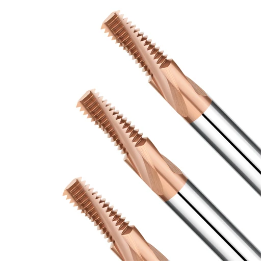
Standard multi-purpose cutters burn out after only three to five holes in 60 HRC stock. You need a dedicated solid carbide thread mill for hardened steel to maintain edge geometry under severe cutting pressures. Skip sharp, positive cutting rakes; they chip instantly. Use a reinforced zero or slightly negative rake, wide relief angles, and a slow 20° to 30° flute helix to maximize core cross-sectional rigidity.
Choose heat-resistant nanocomposite PVD coatings like TiAlSiN over legacy TiCN formulations. In dry or MQL cuts, the high-aluminum matrix generates an in-situ corundum thermal shield at temperatures exceeding 1100°C. This barrier prevents cutting heat from softening the tungsten carbide binder. If the carbide substrate yields, the edge blunts immediately and plows micro-burrs along the profile.
Multi-Pass Machining: Radial Layering to Eliminate Work-Hardened Burrs
Taking a full-depth thread pass in hardened steel guarantees white-layer burrs on every crest. Divide your radial cut depth (ae) across multiple passes. Take a roughing pass to remove 70% to 80% of the thread volume, followed by two progressively lighter finishing cuts down to 0.03 mm. Bump the feed per tooth slightly on the finish cut so the edge bites beneath the glazed shear layer.
Skipping radial passes to save cycle seconds triggers friction spikes that push local surface hardness past 64 HRC. Those brittle burrs snap off inside hydraulic lines during operation, causing severe component seizures. Always conclude your cycle with a zero-depth spring pass along the programmed path. The natural elastic recovery of the shank sweeps away residual scales, leaving a clean thread.

Programming and Process Strategies: Practical Application of Thread Milling Burr Prevention
When premium tools in high-rigidity holders still leave fringes on threaded holes, the issue is almost always the NC toolpath. Successful thread milling burr prevention requires deriving motion profiles from chip mechanics rather than default CAM templates. Most standard post-processors focus strictly on collision clearance, ignoring the sudden radial force spikes that hit during helical interpolation.
Process optimization balances axis acceleration limits, tool deflection, and cycle time. Using crude linear plunge moves causes axis lag during multi-axis synchronization, leaving raised flash on the part. By programming smooth lead-in trajectories and calculating true chip loads, we routinely eliminate edge rollover on flight-critical manifolds and medical fittings without secondary benchwork.
Entry and Exit Strategies: Using Arc-In/Arc-Out to Prevent Seam Marks
Plunging a tool straight into a cut wall along a linear vector guarantees an entry gouge and torn metal. When driving a cnc thread milling bit, never shock the full flute profile before the tool enters its steady-state helical path. Linear entry creates an abrupt spike in radial force, squishing unbacked metal outward. Retracting straight out at the bottom leaves an equally heavy burr at the thread terminus.
We recommend a 90-degree quarter-circle or 180-degree semi-circular arc-in paired with a synchronized Z-axis pitch climb. This three-axis move ramps the chip thickness up gradually from zero, spreading cutting forces evenly across the rim. Adding one or two seconds per hole for an arc-in pays off immediately by eliminating manual rework and scrapped parts.
Feed per Tooth and Surface Footage: Preventing Smearing and Work-Hardened Fuzz
Turning down the feed override when threads look fuzzy often makes the problem worse. If the feed per tooth drops below the cutting edge hone, the tool cannot establish a clean shear angle. The contact zone degenerates into pure friction, rolling metal back and forth until a stubborn thread burr clogs the flanks.
For gummy stainless and titanium, push the feed per tooth into a true shearing range (typically 0.03 to 0.08 mm/tooth). Pair that feed with sufficient surface speed to eject heat with the chip before work-hardening sets in. Running too slow invites built-up edge (BUE), which tears out chunks of the thread root when it sloughs off.

Mechanical Removal and Process Integration: Tooling Strategies for Efficient Thread Burr Removal
Zero-burr machining under conservative feeds is not always economical on high-speed production lines. Standardizing an automated thread burr removal pass directly inside the CNC program delivers the most predictable cost-per-part. It replaces uncontrolled bench scraping and protects the geometric accuracy of the first thread pitch.
Manual deburring with hand blades under magnification introduces human error and slows throughput. Hand scrapers also risk rolling over or nicking the lead-in thread crest. By programming the cleanup pass on the machine spindle, you utilize the machine’s native repeatability to deliver clean, ready-to-assemble parts every cycle.
Integrated Chamfering and Threading Cutters: Eliminating Manual Benchwork
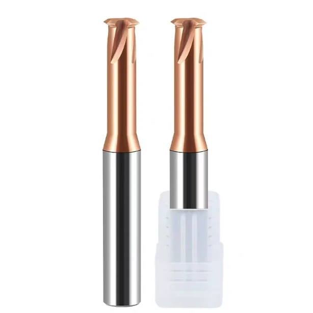
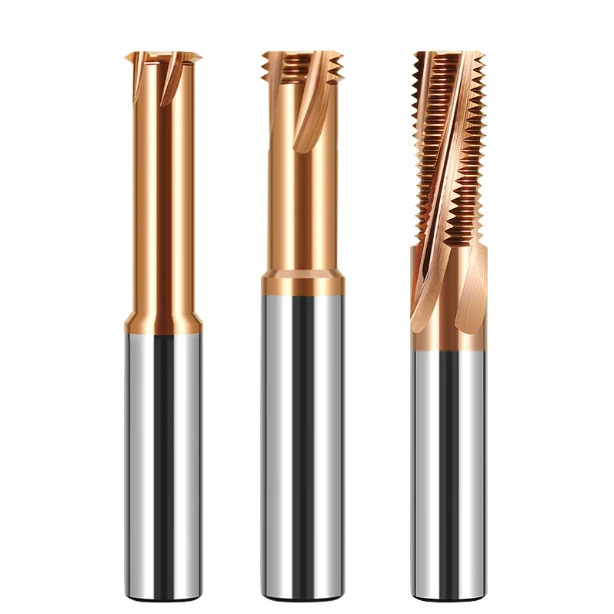
For high-volume production with limited tool capacity, switch to multi-function thread mill tools that combine thread-cutting and chamfering edges on a single solid-carbide body. Once the tool reaches the final thread depth, it cuts the entrance or back chamfer in the same setup. This combination cuts the extrusion path, shearing off potential burrs right at the hole shoulder.
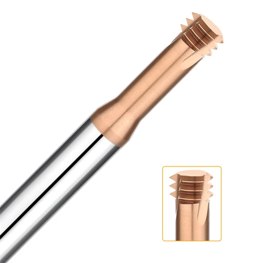
Combination cutters present different cutting forces than straight tools due to the integrated chamfer profile. If your spindle lacks rigidity or you are working in deep bores, use relieved-neck designs to suppress chatter. In our client trials, keeping holder runout under 3 microns with combination tools consistently eliminates manual deburring stations.
Coordinating Pilot Chamfers with Thread Finishing: Standard Shop-Floor Workflows
Gummy alloys like 316 stainless or titanium often leave microscopic flash even when using combination tools. For these tricky jobs, we use a proven four-step sequence: drill, pre-chamfer, helical thread pass, and a final light skim pass with the chamfer tool. Running that second chamfer pass at elevated surface speed with a 0.02 mm radial cut shears off rolled edges cleanly, locking down an automated thread burr removal workflow.
Dialing in this process requires matching stock allowances to your fixture rigidity and machine limits. If you are struggling with thread burrs on an active job, share your material grade, hole depth-to-diameter ratio, or part prints with us. We can review your entry code and cutting forces together to build a clean machining process for your shop.