



Recently, a Detroit stamping die customer contacted our engineering team with an urgent production bottleneck. They were milling M6×1.0 blind threads into D2 tool steel hardened to 63–65 HRC using high-rigidity 5-axis vertical machining centers and shrink-fit tool holders. Standard tooling chipped within the first pass, and when a tool finally finished a hole, the “No-Go” thread plug gauge turned straight to the bottom—the pitch diameter was completely out of spec.
Over the past decade, we have resolved this exact failure across machine shops throughout the US and Europe. Programmers typically blame carbide grade inconsistency, coolant pressure, or PVD coating adhesion, but 200x microscope analysis reveals the real issue: applying pre-hardened tooling habits to ultra-hard steels while ignoring the physics of HRC65 thread mill geometry. At 65 HRC, cutting forces spike exponentially, turning minor tool design compromises into instant edge failures and severe taper.
-
Single-tooth vs. Multi-tooth: Choosing the wrong multi-form thread mill geometry generates extreme radial thrust, causing tool deflection and tapered threads.
-
Micro-edge Treatment: Without negative rakes and edge honing, cutting edges fracture under the impact of hard-phase carbides.
-
Rigidity vs. Chip Clearance: An undersized thread mill core diameter causes chatter, while over-thickening the core chokes chip evacuation.
Reliable hard milling is not just about machine horsepower or premium coatings. Dialing in the correct thread mill geometry for hardened steel is your first line of defense for tool life and gauge tolerance. Are your current thread mills engineered for this extreme cut, or are you forcing standard tools past their physical limits?

Why Standard Thread Mill Geometry Fails on Hardened Steel (60–65 HRC)
A tool that runs smoothly in 40 HRC pre-hardened steel will often fail within half a turn in 60–65 HRC cold-work steel. At extreme hardness, the material’s yield strength spikes, generating massive cutting forces and thermal shock that crush conventional tooling. Standard tools rely on sharp profiles that immediately overload in these conditions. Understanding the physical failure limits of standard HRC65 thread mill geometry on hardened steel is essential to stop scrap parts and broken tools.
These catastrophic tool failures rarely stem from bad CNC programming. Standard cutters feature positive rake angles and thin cutting edges designed for softer, free-machining alloys. Against 65 HRC tool steel, these thin edges take the brunt of intense shear loads and crack under stress. Without adjusting both the macro- and micro-geometry for hardened material, even high-end dynamic spindle balance and low runout holders cannot prevent edge failure.
Analyzing Failure Modes in HRC65 Thread Mill Geometry: Micro-chipping or Stress Overload?
When inspecting damaged tools returned from the field, we focus directly on the primary cutting teeth under magnification. While gross tool fracture usually stems from chip packing or severe radial overload, ultra-hard threading failures almost always start as micro-chipping. High-hardness steel demands that hrc65 thread mill geometry uses reinforced negative rakes and edge honing to generate a protective compressive stress zone. Without that geometry, sharp tips chip immediately against hard carbide particles in the steel.
Micro-chipping and stress overload feed on each other in a rapid chain reaction. Once microscopic flaking begins, the functional clearance angle drops toward zero and creates heavy flank rubbing. Frictional heat builds up fast, causing cutting forces to double in seconds. Even if the machine axis feeds smoothly, the tool shank bends under intense side loads. If the operator does not catch this instantly, micro-chipping turns into complete tool fracture within half a revolution.
A Common Pitfall for Western Mold-Making Customers: Blindly Applying Parameters Used for Pre-hardened Steel
The most common mistake we see in American and European mold shops is carrying over parameters from pre-hardened stock. Programmers take feeds and speeds proven on 40 HRC steel, drop the surface footage by 30%, and run. This ignores the physics of cutting 65 HRC material, where fracture strain changes completely. Running standard feed rates with unoptimized thread mill geometry for hardened steel spikes radial cutting forces and overloads the cutting edges.
We consistently advise shops against chasing aggressive cycle times in a single pass. Forcing pre-hardened cutting parameters onto 65 HRC material pushes cutting forces straight into the tool tip and spindle bearings. The result is always tool deflection, tapered threads, chatter marks, and parts failing the Go/No-Go gage test. In hardened steel, breaking the radial depth of cut into multiple climb-milling passes reliably preserves both tool life and thread tolerance.
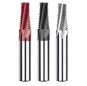
Single-Form vs Multi-Form Thread Mill Geometry: Shop-Floor Selection Trade-offs
When buying HRC65 thread mills or posting toolpaths, choosing the tooth profile matters more than choosing the coating brand. Many programmers prefer multi-tooth cutters because a single 360-degree interpolation completes the entire thread quickly. Above 60 HRC, however, choosing between single-form vs multi-form thread mill geometry is no longer just about cycle time. It is a critical mechanical calculation that determines part quality, tool survival, and spindle performance.
In our field experience, shops scrap expensive parts when they treat hardened steel like standard alloy steel. Machining hardened materials comes down to controlling radial cutting pressure. More teeth in the cut mean a larger instantaneous contact patch, which multiplies cutting forces. Because 65 HRC steel has almost zero plastic deformation, your choice of tool geometry must balance machine rigidity, spindle runout, and part workholding stability.
Contact Area and Radial Force Bottlenecks with Multi-Form Thread Mill Geometry in 65 HRC Blind Holes
Running multi-form thread mill geometry in a 65 HRC blind hole forces three to five teeth into the cut at the same time, even at 1.5xD depths. Hardened steel produces fine, powdery chips under shear rather than continuous curls, pushing intense normal forces against each tooth. These cutting forces combine into heavy radial loads that easily flex small-diameter solid carbide shanks.
On the shop floor, this deflection creates a classic tapered thread: the hole entrance is on-size, but the Go gage binds near the bottom. We helped an injection mold maker troubleshoot this exact issue when they pushed multi-form tools to shave 40 seconds per hole. High cutting forces caused severe tool push-off, leaving chatter marks and burnished flanks near the floor of the blind hole while quickly chipping the lower teeth.
Why We Recommend Single-Form Thread Mill Geometry for 2D/3D Deep Holes or Deformation-Prone Parts
For holes deeper than 2xD or parts with weak setups like thin walls and long overhangs, we strongly recommend single-form thread mill geometry. A single-tooth design engages only one thread profile in the cut at any point along the helical path. This minimizes the cutting contact arc, drops radial forces to near zero, and keeps tool deflection well under a few microns.
A single-form tool takes longer because it must helix down the entire thread length pass by pass, but it delivers absolute dimensional precision. In thin-walled hardened parts, low cutting resistance stops chatter and prevents localized thermal distortion. The open profile also leaves massive room for chip clearing. High-pressure air blasts can reach the cutting zone directly, preventing powdery chips from packing at the hole bottom and breaking teeth.
Comparative Test Data: Actual Performance of the Two Tooth Geometries Regarding Tip Wear, Entry Path, and Thread Gauge Concentricity
In our testing facility, we ran head-to-head tool life trials on 64 HRC punch plates (M8×1.25, 16 mm depth) to compare different thread mill geometry options. While multi-form cutters cut cycle times by roughly 70%, their bottom teeth showed over 0.04 mm of flank wear by hole eight. As wear accelerated, pitch diameter runout between the top and bottom of the hole quickly passed 0.025 mm, failing the thread plug gage inspection.
By contrast, single-form tools maintained consistent, light-load climb cuts throughout the test. Even though the tool spent more total time in cut, tooth wear progressed slowly and evenly across all passes. After threading 30 consecutive holes, pitch diameter runout stayed under 0.008 mm, achieving a 100% first-pass gage acceptance rate. For ultra-hard materials, trading cycle seconds for reliable hole quality remains the most cost-effective path on the shop floor.
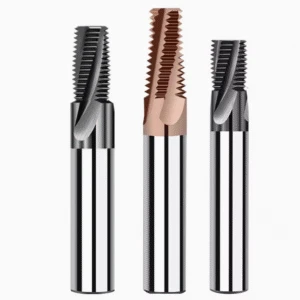
Thread Mill Rigidity and Core Diameter: Addressing the Physics Behind Tool Deflection and Tapered Threads
When thread milling steel hardened past 60 HRC, operators frequently face a frustrating taper defect: threads loose at the entry but tight at the bottom. You can drop the interpolation feed rate to a crawl, but the pitch diameter at the hole bottom remains undersized. This deviation rarely comes from machine positioning errors. It stems directly from microscopic tool deflection under extreme cutting resistance, making thread mill rigidity your primary physical line of defense.
During plant audits, we often mount a dial indicator on the tool tip to measure static deflection under radial load. Machining 65 HRC alloys generates severe tool push-off compared to mild steels or aluminum. A mere 2 to 3 microns of elastic flex translates into massive pitch diameter errors along the thread flanks. To hold tight gage tolerances in deep-hole hard milling, you must design a massive core cross-section that prevents deflection from the start.
Exponential Gains in Bending Rigidity via Increased Thread Mill Core Diameter
Beam deflection physics is unforgiving: the area moment of inertia of a solid cylinder scales with the fourth power of its diameter. Increasing the thread mill core diameter creates exponential gains in dynamic bending stiffness. Stepping up core thickness from the standard 50% to 65% or 70% of cutter diameter drastically cuts radial deflection at the tip under identical cutting pressures.
We proved this while developing custom M10 fine-pitch tools for a European die caster running 63 HRC powder-metal steel. Standard-core cutters left a 0.03 mm bottom taper even with multi-pass spring cuts. Upgrading to a reinforced core cutter dropped that taper below 0.006 mm. In hardened steel, preserving an extra half-millimeter of solid carbide in the core provides the physical stiffness needed to stop deflection entirely.
The Critical Trade-off Between Chip-Evacuation Flute Space and Thread Mill Rigidity
Thickening the cutter core inevitably runs into a hard physical constraint: flute gullet depth. Expanding the solid cross-section reduces chip evacuation volume, and an oversized thread mill core diameter leaves zero room for chip flow. Even though 65 HRC steel forms fine, abrasive micro-dust rather than curly chips, failing to blast this debris away immediately causes dangerous re-cutting in the flutes.
We have diagnosed dozens of sudden tool fractures where the shank never exceeded its elastic load limit. Instead, packed debris wedged between the hole wall and flute root, locking the cutter instantly. We solve this by using shallow, parabolic flutes paired with a smooth rake ramp. This geometry maximizes core mass while allowing shop air blasts to eject abrasive micro-chips freely from blind holes.
Field Troubleshooting: When the Thread Gauge Binds, Should You Check Overhang Ratio and Clamping Rigidity First?
When a machined thread fails inspection because the Go gage binds at the bottom, never rush to adjust the D-offset on your CNC control. Many operators increase negative tool radius wear compensation to force the gage through. This overcuts the hole entrance, blows out the No-Go tolerance, and scraps the mold component. You must troubleshoot mechanical setup errors before touching offset numbers.
Our first diagnostic rule is verifying holder runout and overhang ratio. If tool stick-out exceeds three times the shank diameter, or if you use standard ER collets instead of shrink-fit or hydraulic holders, runout destroys thread mill rigidity immediately. Lock total spindle-to-tip runout under 3 microns and seat the tool as short as possible. Only then should you calculate tool flex and tweak radial step-overs.
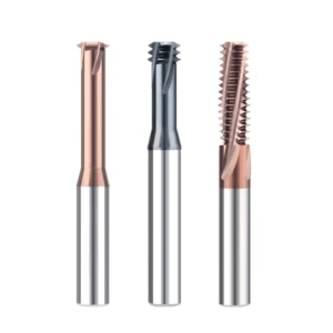
Controlling Thread Mill Chatter: Vibration-Damping Design via Helix Angle and Tooth Pitch
Machining 60–65 HRC steel should produce a crisp, steady hum, never a high-pitched shriek. High-frequency squealing signals that the tool is hammering the workpiece, leaving fish-scale chatter marks across the thread flanks. Because sub-micron carbide grades have limited fracture toughness, persistent vibration chips cutting edges in seconds. Effectively suppressing thread mill chatter is critical for maintaining surface finish and tool life.
Many machinists try to eliminate vibration by dropping spindle speed, but that often backfires. Lower RPM with the same feed per tooth increases chip load, triggering low-frequency tool deflection. Vibration comes from periodic cutting force pulses syncing together. Breaking this harmonic resonance requires specialized asymmetrical flute geometry that disrupts cutting impact frequencies at the source.
The Direct Impact of Thread Mill Helix Angle on Axial Force Components and Impact Stability
Flute inclination is frequently overlooked during tooling audits, yet the thread mill helix angle dictates how cutting forces split upon engagement. Straight flutes hit hardened steel with an abrupt, full-face impact that hammers the spindle bearings. An optimized helix creates a smooth shearing action, dividing cutting energy into radial and axial vectors that cushion entry shocks.
However, steep helix angles used for aluminum milling backfire on ultra-hard metals. Angles above 45 degrees generate high axial pull-out forces, inducing micro-shifting in the spindle drawbar that degrades thread pitch accuracy. For 60–65 HRC steel, we hold the thread mill helix angle between 30 and 40 degrees. This provides smooth shearing without overloading the spindle’s axial retention system.
Field Effectiveness of Unequal Helix Angles and Unequal Tooth Pitch Designs in Suppressing Thread Mill Chatter
Examine the business end of a dedicated hard-milling cutter and you will notice irregular flute spacing rather than symmetrical 90-degree flutes. Combining unequal tooth spacing with variable helix angles physically prevents self-excited thread mill chatter. Because each cutting edge enters the cut at different time intervals, force pulses never phase-align, stopping harmonic chatter before it starts.
We verified this with real-time vibration spectrum analysis on a medical stamping die. A standard four-flute cutter produced a massive resonant spike at 6500 Hz, leaving heavy chatter on the thread flanks. Switching to an asymmetrical geometry under identical feeds and speeds flattened that peak into smooth, low-amplitude noise. Thread roughness dropped from Ra 1.6 to under Ra 0.4 purely through built-in geometric damping.
Anti-Vibration Parameters for Climb Milling Combined with Small-Step Helical Interpolation
Beyond tool geometry, your programmed entry path acts as the final barrier against chatter. When milling 65 HRC alloys, always run climb milling toolpaths. Climb milling enters at maximum chip thickness and tapers to zero, generating compressive loads that shield the cutting edge. Conventional milling rubs the flank against work-hardened surfaces, generating excessive frictional heat and instant chatter.
Never attempt full thread depth in a single radial pass. We recommend splitting the radial stock into two or three progressive passes: 65% on the roughing pass, 30% on the semi-finish pass, and a final spring pass of 0.01 to 0.02 mm. This near-zero chip load on the finish cut eliminates lateral deflection, clears out thread mill chatter, and guarantees that your thread plug gages pass inspection every time.
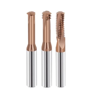
Thread Mill Cutting Edge Geometry: Edge Reinforcement Details for High-Hardness Applications
Core thickness and helix angle establish macroscopic stiffness, but the micro-features on the cutting edge take the full brunt of 65 HRC stock. Machinists often test sharpness by scraping an edge against a thumbnail, looking for razor keenness. In hardened steel milling, that keenness causes instant chipping. The extreme yield strength of quenched alloys demands structural toughness. Designing proper thread mill cutting edge geometry is a precise balancing act between cutting sharpness and compressive strength.
In our metallurgical evaluations, tool failures rarely start as gradual flank wear. They begin as micro-cracks spreading along carbide grain boundaries under intense shear loads and frictional heat. Without stress relief along the edge margin, mechanical shock fractures the cutter within dozens of revolutions. To thread thousands of holes reliably in hardened tool steel, macro-level clearances must work together with micro-level edge prep.
Negative Rake Angle Combined with Reinforced Clearance Angle: The Foundation of Chipping Resistance in Thread Mill Cutting Edge Geometry
Positive rake angles cut freely in pre-hardened steels, but they leave a fragile wedge angle that traps heat during 65 HRC milling. Our hard-milling tools use reinforced negative rake faces instead. A negative rake directs cutting forces into compression rather than tension, exploiting carbide’s natural compressive strength. This heavy-duty wedge is the core mechanical foundation of thread mill cutting edge geometry for withstanding cyclic impact.
Because negative rakes generate higher cutting resistance, relief angle clearance must be balanced carefully. Hardened steel springs back elastically against the cutter flank, causing friction and heat. We combat this using a dual-relief profile: a narrow primary land reinforces the edge, while a steeper secondary clearance clears the cut immediately. This geometry eliminates flank burnishing on 64 HRC stamping dies and dramatically cuts tool chipping.
Micro-Edge Treatment (Edge Honing & T-Land): Micron-Level Honing for Coating Adhesion and Protection Against Initial Wear
Freshly ground cutting edges contain microscopic grinding serrations along the perimeter. Running an unhoned tool into 65 HRC stock triggers instant micro-chipping on the very first thread pass. Applying a controlled hone or negative T-land smooths the thread mill cutting edge with a defined radius. This modification rounds off sharp stress risers and shields the cutting perimeter against shock loads.
Edge preparation also protects coating integrity. Advanced nano-coatings like AlTiN or AlCrN cannot adhere evenly to a razor-sharp edge with a near-zero radius, causing early flaking. An 8 to 15-micron hone provides a stable foundation for dense, uniform coating deposition. In production trials at client shops, properly honed tools wore smoothly across their full lifespan without the catastrophic delamination typical of raw edges.
Truncated Tip and Finishing Design: Eliminating Stress Concentration at the Thread Root and Extending Tip Life
The structural weak link of any thread form is the theoretical sharp corner at the tip. Under severe 65 HRC cutting forces, theoretical 60-degree points snap off almost immediately. Operators often find the pitch diameter still passes inspection while the crests have worn flat. To prevent this, our thread mill geometry for hardened steel features a truncated tip with a micro-radius blend that eliminates weak, pointed corners entirely.
Adding a small flat land and blending it with micro-chamfers redistributes tensile forces along the crest boundary. This design prevents high stress concentrations that could crack the root of the internal thread. In high-tensile mold applications, a truncated, blended tip protects the cutter tooth from chipping. It also produces consistent root radii that routinely pass rigorous aerospace and automotive fatigue inspections.
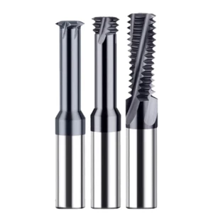
Field Checklist: Selecting the Best Thread Mill Geometry for Hardened Steel
Translating cutting mechanics into reliable production parts demands an uncompromising shop-floor checklist. At 60 to 65 HRC, there is no room for guesswork; every broken tool or oversized pitch diameter points directly to broken force equilibrium. Before loading programs and touching off tools, running a complete physical audit is essential. Choosing the best thread mill geometry for hardened steel requires verifying every operating constraint in advance.
Most scrapped mold components stem from ignoring trade-offs during tool selection. A thick core stops deflection but chokes chip gullets. Multi-tooth designs slash cycle times but demand rigid setups and massive spindles. Negative rakes absorb shock but require higher torque and multi-pass programming. Evaluating these trade-offs against your machine setup ensures consistent hole quality without breaking tools.
Reviewing Your Operating Conditions: Rigid Constraints Imposed by Hole Depth, Diameter, and Batch Size on Tool Geometry
Start your review by evaluating hole depth, diameter, and setup rigidity directly from the part print. If you are milling blind holes deeper than 2.5xD or handling thin-walled fixtures, choose single-form tooling. Forget chasing rapid cycle times here; near-zero radial forces provide total control over taper and pitch concentricity. If you are cutting shallow holes on a rigid machining center with shrink-fit holders, run multi-flute tools to speed up production.
Hole diameter also dictates core dimensions and flute depth. If you are milling small threads like M3 or M4 in hardened steel, flute packing is a bigger threat than edge wear. Drop your chip load, run high-pressure dry air blasts, and prioritize flute clearance over cycle speed. Selecting the right thread mill geometry requires adapting to real-world part constraints rather than forcing pre-hardened milling strategies onto 65 HRC jobs.
Geometric Parameters and Runout Metrics to Verify Before Test-Cutting with 65 HRC-Rated Tools
Before mounting a tool in the spindle, inspect it under a toolmaker’s microscope. If the cutting edge shows ragged grinding burrs and lacks a visible edge hone, it will chip within seconds of entering hardened tool steel. Next, mount the holder and check total dynamic runout at the tool tip with a test indicator. If radial runout exceeds 0.003 mm, one tooth will take all the impact, triggering instant failure.
Verify the negative rake angle, the primary relief clearance, and the tip truncation before cutting. If you are battling tool deflection, binding thread gages, or premature tool wear on 60–65 HRC jobs, let us know. You can share your part prints, heat-treat hardness ratings, and toolpaths with our engineering team anytime. We are always glad to review cutting geometry with fellow machinists to solve tough shop-floor problems.





