



Last month, a precision stamping die client in Stuttgart, Germany reached out to us with an urgent production bottleneck. They were threading M3×0.5 holes in 1.2379/D2 cold-work die steel hardened to HRC 64–66. Using off-the-shelf 45° high-helix thread mills, their tools failed almost immediately. By the second hole, the neck suffered microscopic fatigue fractures or catastrophic edge chipping that locked the cutter inside the workpiece.
This is not an isolated breakdown. Over our sixteen years of troubleshooting setups across North America and Europe, we have seen this failure pattern repeatedly. Seasoned CAM programmers rely on high helix angles for light cutting action and smooth chip evacuation in pre-hardened steels. However, once workpiece hardness hits HRC 65, those conventional machining rules collapse.
In glass-hard metals, the design of a thread mill helix angle for hardened steel governs structural mechanics rather than chip flow. Force dynamometers and wear microscopes show that steep helix angles produce massive, instantaneous axial pull-out forces. Combined with extreme workpiece pushback, this creates destructive cyclic stress at the neck. The steep angle also thins the cutting edge wedge, overloading the ultra-fine-grain carbide substrate.
Conversely, a pure straight-flute tool sacrifices smooth, progressive material entry. The resulting shock loads and chatter destroy flank coatings within seconds. How, then, do you balance flute geometry, effective rake, torsional stiffness, and overall thread mill tool life? When your finish-machined HRC 65 workpiece costs tens of thousands of dollars, can you really afford to gamble on a generic catalog tool?

Thread Mill Helix Angle for Hardened Steel: Why the Standard 40°–45° Helix Angle Doesn’t Apply
For aluminum, carbon steel, or 300-series stainless, a 40° to 45° helix angle is standard shop practice. The sharp cutting edge shears continuous chips and lifts thermal energy away through the flutes. However, applying this approach to HRC 65 tool steels triggers immediate machine alarms and ruined parts. Under extreme hardness, shear deformation gives way to high-pressure extrusion and localized brittle micro-fracture.
Our tooling trials confirm that optimizing the thread mill helix angle for hardened steel is a direct trade-off between wedge strength and entry stability. High helix angles offer smooth progressive engagement. Yet grinding them severely thins the backing behind the cutting edge. Under high-cycle impact against hardened martensite, this weakened cross-section cannot hold up. Instead of normal progressive wear, the tool chips and flakes within its first few passes.
Insights from Tool Breakage Cases in European and American Mold Shops: The Fatal Axial Pull-Out Force Caused by High Helix Angles When Machining HRC65 Hardened Steel
Last year, we resolved a severe breakage issue for an automotive die manufacturer in the US Midwest. They were milling M4 threads in powder-metallurgy punches using a premium 42° helix solid-carbide tool on a 5-axis center. The failure was consistent: within three seconds of entry, the tool snapped cleanly where the relief neck met the flutes. The shop suspected spindle runout or weak shrink-fit clamping, but our live cutting data proved otherwise.
The real failure mechanism was an unchecked thread mill helix angle cutting force vector. High helix angles convert heavy radial resistance into an intense axial pull-out force directed down the tool axis. In soft steels, this force is harmless. In HRC 65 steel, immense radial resistance converts into violent axial tension. The slender neck must fight high cutting torque and axial pull simultaneously. This combined load quickly exceeds the carbide’s ultimate transverse rupture strength.
Why We Set the Helix Angle for Thread Mills (for Hardened Mold Steels 1.2379/D2/S7) Within the 15°–25° Range
To eliminate early tensile failures in hardened tool steels (D2, A2, and S7), we redesigned our flute profiles from scratch. We dropped generic geometries and locked our baseline helix between 15° and 25°. You might wonder why we avoid a 0° straight flute entirely. While straight flutes offer maximum cross-sectional rigidity, full-edge entry creates massive shock loads. This severe hammering causes expensive PVD wear coatings to spall off almost immediately.
A 15° to 25° helix hits the ideal mechanical sweet spot. It provides enough angle for a smooth helical entry, avoiding the destructive shock of straight flutes. At the same time, it suppresses axial pull-out forces and redirects tool pressure into the rigid radial plane of the machine spindle. Built as a dedicated thread mill for hardened steel, this profile pairs with a 20% thicker core and a reinforced negative rake to prevent tool deflection under extreme loads.
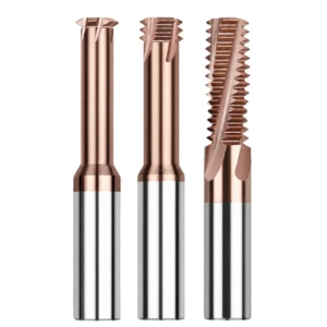
Thread Mill Helix Angle and Cutting Force: The Mechanical Trade-off Between Helix Angle, Radial Rigidity, and Cutting Resistance Distribution
Shop engineers frequently ask us: “Why does the machine spindle load curve flatten out when we reduce the helix angle?” Many assume a steeper angle cuts more freely with less resistance. That logic only holds when chips shear continuously. In HRC 65 materials, the tool must crush and micro-fracture the cut zone under extreme pressure. Under these conditions, standard cutting force vectors shift drastically.
Dynamometer testing reveals that managing the thread mill helix angle cutting force creates a genuine force-stabilization effect. Dropping the helix from 45° to roughly 20° drops the axial force component dramatically. Unpredictable, multi-axis cutting loads transform into a stable, single-plane load. This reduces cyclic stress at the neck overhang, letting the machine spindle handle cutting loads through its stiffest radial bearings without inducing chatter.
How Reducing the Helix Angle Balances Cutting Force Distribution and Eliminates Micron-Level Workpiece Deflection
When machining threads in hardened molds, you have likely seen pitch diameter taper—where the “Go” gage binds while the “No-Go” enters easily. Programmers often compensate by adjusting toolpaths or spring passes. While diagnosing errors for a Swiss watch mold maker, we found their standard tools suffered extreme lateral push-off. High helix angles transform heavy lateral resistance into bending and torsional loads, causing unpredictable tip deflection.
To stop this dynamic deflection, we recommend running an application-specific thread mill for hardened steel. A lower helix confines cutting forces almost entirely to the plane perpendicular to the tool centerline. Tangential thrust transforms into a pure radial load supported by machine rigidity. This design cuts lateral tool deflection at the neck by over 40%, holding tight micron-level tolerances from the hole entrance straight to the bottom.
Interplay between Helix Angle, Effective Rake Angle, and Cutting Edge Strength: Avoiding the Micro-Chipping Threshold for HRC65 Materials
When grinding custom geometries on 5-axis CNC tool grinders, we watch the link between helix angles and cutting edge profiles closely. Many machinists look only at the print’s static rake angle. They miss that increasing the helix angle increases the effective normal rake during the cut, making the wedge angle sharper and more fragile. Against quenched martensite, a fragile cutting wedge chips the instant it contacts the work.
Field tests show that maximizing thread mill tool life in ultra-hard steels requires staying clear of this chipping threshold. By dropping the helix angle to roughly 20°, we grind a robust negative-rake protective land and micro-honed edge directly into the flute. This geometry provides deep carbide substrate support right behind the cutting edge. Operating like a rigid micro-planer, this design crushes and shears hard surfaces smoothly, preventing edge breakout and ensuring predictable flank wear.
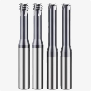
Thread Mill Flute Geometry: Engineering the Match Between Flute Profile and Helix Angle
When threading ultra-hard materials, machinists often focus solely on tool diameter and PVD coatings. They overlook the engineering logic inside the flute cross-section. In HRC65 steel, the flute does far more than clear chips; it governs torsional rigidity and dynamic natural frequency under severe radial load. Cutting tools with lower helix angles naturally have longer flute paths. If you grind them with standard deep, concave flutes, you slash the tool’s bending stiffness in half.
Through extensive grinding trials on 5-axis CNC tool grinders, we treat thread mill flute geometry as an integrated structural system. A shallow helix shifts how chips flow off the cutting edge. Flutes that curve too sharply cause hard particles to stall and pack in the gullet floor. Conversely, overly shallow flutes lack room for chip evacuation. We carefully balance the transition radius and OD back-wall thickness. This channels heavy cutting forces into the solid tool shank, preventing fatigue cracks at the flute root.
Balancing Flute Depth and Core Diameter for Ultra-Hard Workpieces Producing Powdery Chips
Machining HRC65 hardened die steel creates a unique chip profile. You will never see continuous curled chips curling out of the hole. Instead, the material shears away as abrasive, iron-dust micro-particles known as “powdery chips.” These sand-like particles do not tangle or pack like ductile ribbons. Machinists who demand deep flutes for this operation misunderstand the mechanics and needlessly surrender critical tool core thickness.
Our field tests in precision toolrooms helped us optimize core ratios for the HRC65 thread end mill. We reduce traditional flute depth by roughly 30%, which boosts the solid core diameter to 65%–72% of the tool’s outer diameter. High-pressure air blasts clear these powdery fines easily from shallow U-shaped pockets. The trade-off is massive: the thick core delivers exceptional geometric stiffness. It eliminates radial push-off and prevents tool deflection, even at long overhang ratios.
Multi-Flute Unequal Spacing Combined with Specific Helix Angles: Key Geometric Features to Suppress High-Frequency Chatter in Hard Materials
Machining materials as hard as ceramics often provokes high-frequency harmonic chatter. If a thread mill features equal flute spacing and a uniform helix, each tooth impacts the part at identical time intervals. This harmonic stacking builds severe resonant peaks that chip fragile flank edges immediately. We helped an aerospace supplier whose tools broke on every single hole. The root cause was simply that their spindle speed matched the resonant frequency of their symmetrical flutes.
We eliminate this self-excited vibration by pairing low helix angles with unequal flute indexing. In a 4-flute design, we space teeth asymmetrically (such as alternating 87° and 93° pockets). As the cutter engages the hardened workpiece, cutting impact phases are disrupted. Adjacent teeth hit peak loads at different times, stopping resonant standing waves from forming. This asymmetry dampens machine vibration at the source, dramatically extending your overall thread mill tool life.

Thread Mill Helix Angle for Small Threads: M1.6–M4 Micro-Deep-Hole Thread Milling
Threading small holes from M1.6 to M4 in HRC30 material gives you plenty of margin for error. Standard tool geometries and speeds work reliably. However, once workpiece hardness reaches HRC65 and the depth ratio exceeds 2D or 2.5D, micro-scale mechanics amplify every weakness. The tool neck is often barely 1 mm in diameter. It must survive crushing radial forces inside a microscopic hole. Picking the wrong helix angle guarantees immediate tool failure.
Designing a thread mill helix angle for small threads demands a total rethink of tool mechanics. Large thread mills have enough core mass to absorb complex alternating loads. Micro-diameter cutters have zero margin for error at the neck. High helix angles create excessive axial pull on tiny necks while thinning the relief angle behind microscopic thread forms. We reject steep helix angles for small threads, standardizing on a rigid 10° to 18° range to maximize cross-sectional shear strength.
Neck-Breakage Mechanism in Micro-Diameter Thread Mills for Hardened Steel: Sharp Drop in Torsional Rigidity of the Micro-Overhang Due to Excessive Helix Angles
We recently assisted a German medical manufacturer struggling to thread micro-bone plates. They were milling M2 blind holes in hardened alloy, but tools repeatedly snapped at the neck after two or three parts. High-magnification microscopy showed that failure did not start at the cutting edge. Instead, the neck sheared at a 45° angle right where the relief radius blended into the flute. The culprit was an off-the-shelf micro-mill with an aggressive 30° helix.
When selecting an optimized thread mill for hardened steel for deep micro-holes, you must respect the link between helix angle and torsional section modulus. A steep helix removes solid core volume unevenly at the flute runout, forming a localized stress riser. When cutting HRC65 steel, immense cutting resistance resists the spindle rotation. The steep helix creates axial tension that merges with rotational torque, instantly exceeding the transverse rupture strength of the sub-micron carbide neck.
Challenges in Chip Evacuation and Tool Grinding for Small-Diameter Blind-Hole Threading: High-Pressure Internal Cooling/Air Cooling Combined with Specific Low-Helix-Angle Neck Relief Designs
In tiny blind holes, clogged chips break tools long before the cutting edge wears out. Many machinists try using standard liquid coolant. However, in small M2 or M3 cavities, viscous coolant mixes with fine powder, forming an abrasive paste that re-cuts and wedges the tool. Grinding these micro-cutters requires extreme care. The end face needs secondary clearance to avoid bottom corners, while internal through-coolant ports must aim directly at the cutting zone.
To thread micro blind holes in an HRC65 thread end mill setup, pair a low helix angle with high-pressure air. We recommend running clean, dry air above 20 bar (or high-pressure MQL) with a 12°–15° gentle flute profile. The shallow flute guides abrasive dust upward like a pneumatic piston, clearing it instantly from the bore. This shallow angle also leaves extra carbide at the tool tip, allowing a sturdy micro-chamfer that prevents chipping when reversing at the bottom of blind holes.
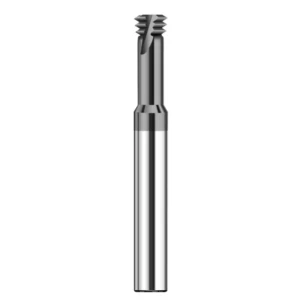
Thread Mill Tool Life: Practical Insights on Extending Tool Life through Optimized Helix Angles, Toolpath Strategies, and Coating Matching
When dealing with HRC65 parts, many shop managers blame early tool failure on carbide grain size or poor coating adhesion. However, extreme hardness machining is never a single-variable problem. It is a systems engineering challenge that connects tool geometry, CAM toolpaths, and thermochemical coatings. Tweaking one factor while ignoring cutting dynamics guarantees failure against high mechanical shock and intense cutting heat.
Field data proves that maximizing thread mill tool life requires dampening the severe shock load at initial entry. A low helix angle creates a beefier, reinforced cutting edge that prevents load spikes. When paired with arc-in entries and heat-resistant nanocomposite coatings, the cutting teeth avoid catastrophic micro-chipping. The tool settles into predictable, steady flank wear, making tool life repeatable across long production runs.
Real-World CAM Toolpath Validation: Quantifiable Tool Life Improvements via Climb Milling and Multi-Pass Radial Feed
We frequently see programmers push for faster cycle times by cutting full thread depths in a single pass. In HRC65 steel, this burns out cutting edges in fewer than three holes. We recently tackled this with a US blanking die manufacturer cutting M6×1.0 blind threads. We eliminated single-pass cutting entirely and switched to climb milling with a three-pass radial step-over, splitting the cut into 60%, 30%, and a final 10% spring pass.
Paired with a purpose-built thread mill for hardened steel, this multi-pass approach delivered massive stability gains. Climb milling ensures the chip starts thick and thins out, preventing flank rubbing and frictional heat buildup. The radial step-overs keep cutting forces well within the tool core’s elastic limit. Tool output jumped from 4 holes per tool to over 35 holes, while holding pitch diameter straight and true.
Synergy between Helix Angle and Super-Hard Nanocomposite Coatings (AlTiN/AlCrN): Suppressing Flank Wear
Many shops assume thicker coatings solve wear issues, but cutting zone temperatures in HRC65 steel routinely exceed 900°C. If tool geometry flexes under load, even the best coating flakes off in seconds. High performance demands micro-hardness over 3300 HV, high oxidation resistance, and proper rake angles. For low-helix cutters, we rely on AlTiN or silicon-doped nanocomposites (AlCrN/nc-AlCrTiN) for their hot hardness and lubricity.
Applying this coating chemistry to an HRC65 thread end mill creates an essential mechanical synergy. The low helix angle provides a solid carbide foundation right behind the flank face. This rigidity eliminates micro-flexing, preventing coating shear delamination at the carbide boundary. The hard, dense film then shrugs off abrasive powdery chips, stopping early crater wear and keeping flank wear slow, even, and manageable.
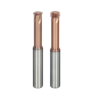
Thread Mill for Hardened Steel: A Standardized Selection Checklist for Machining HRC65 Hardened Steel Threads
We gathered years of shop-floor data across Europe and the US to build this practical tooling checklist. In most cases, chipped cutting edges and out-of-round threads do not stem from bad machines or poor operators. They happen because the tool geometry does not match the setup. In HRC65 tool steel, trial-and-error gets expensive fast. Every machining parameter needs to be part of a verified, closed-loop process.
Our standards establish strict entry rules when choosing a thread mill for hardened steel. From low-helix geometry and unequal flute spacing to high-temperature coatings and climb milling, these rules remove guesswork. They help you balance core rigidity with chip clearing directly in the cut. This turns high-risk thread milling in expensive, pre-hardened components into a predictable, repeatable operation.
Quickly Determine the Recommended Helix Angle Based on Pitch, L/D Ratio, and Hole Type
When sizing a cutter, ignore generic catalog charts and look directly at your depth-to-diameter (L/D) ratio and chip room. If you are milling through-holes or shallow blind holes under 1.5D, chips clear with minimal resistance. You can run a 20° to 25° helix for smooth helical entry and clean cuts. If you face deep holes beyond 2D or small threads under M4, drop to a 12° to 15° helix to cut axial pull-out forces and maximize core stiffness.
Chip evacuation changes drastically between through and blind holes. If you are milling deep blind holes in hardened steel, choose a dedicated HRC65 thread end mill with bottom neck relief and a low helix angle. Blast dry, filtered air at 20+ bar down the bore to clear fine dust without packing the bottom. For through-holes, chips fall free, letting you focus entirely on cutting edge strength. Use this framework to troubleshoot your current tooling bottlenecks.
Field Guide for Fine-Tuning Feed per Tooth and Cutting Speed
Even with ideal helix angles and flute shapes, pushing cutting parameters past physical limits destroys edges fast. In HRC65 steel, surface footage drives heat generation, while feed per tooth dictates unit pressure on the honed edge. Under dry or air-blast conditions, keep cutting speed strictly between 30 and 45 m/min. This lets the AlTiN or AlCrN coating manage thermal loads without heat-checking or micro-cracking the carbide substrate.
Dial in your feed rates with the multi-pass strategy in mind. If you are roughing with a low-helix cutter, run 0.015 to 0.03 mm/tooth to ensure the edge shears clean steel instead of rubbing the hardened skin. If you are taking a final 0.02 mm spring pass, drop to 0.008 to 0.012 mm/tooth to eliminate tool push-off and dial in pitch tolerances. If you have a challenging hardened steel blueprint or high scrap rates, share your material grade and setup—we can analyze the cutting physics together.





