



Three months ago, a German client making stamping dies reached out with an urgent bottleneck. They were milling M6×1.0 blind-hole threads into CPM 10V inserts hardened to HRC 62–64 using a commercial carbide tool. Every tool chipped at the tooth tip by the third hole. Macro-fracture inspection showed no standard flank wear or torque breakage. Instead, severe chatter at the back of the flute during helical entry fractured the profile.
In sixteen years of tooling engineering, we have solved this exact failure hundreds of times. Shops often blame the PVD coating or carbide grain size, switching to expensive nano-coatings that only delay chipping by two or three holes. Through countless SEM and optical failure analyses, we found the true bottleneck: thread mill flute geometry for hardened steel is often overlooked, yet it dictates whether the tool cuts cleanly or snaps under extreme load.
Hardened steels produce negligible plastic deformation, generating abrasive, microscopic powdery chips under severe specific cutting resistance. Conventional flute profiles face three immediate dead ends:
-
Rigidity vs chip room: Shallow flutes increase bending stiffness but trap hot powder, causing micro-welding and catastrophic edge fractures.
-
Flute volume vs. chatter: Deep flutes evacuate debris better, but the loss of cross-sectional mass causes immediate harmonic deflection.
-
Micro-edge durability: Without a dedicated micro-land, even sub-micron carbide edges crumble within seconds against an HRC60+ surface layer.
To deliver predictable tool life from an HRC65 thread milling cutter, you must re-engineer the flute profile from the core out. That means tuning unequal flute index angles to cancel vibration, applying negative T-lands to redirect shear stress, and shaping the flute gullet around pressurized air-blast dynamics.
If your machining center is breaking thread mills, tearing threads, or drifting off pitch diameter in HRC60+ mold steels, ask yourself this: Is your cutting data really wrong, or was your tool’s flute geometry never built for this hardness?
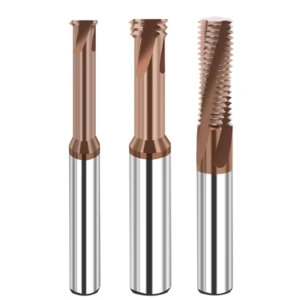
The Critical Balance Between Tool Rigidity and Chip Capacity: Core Considerations for Thread Mill Flute Geometry for Hardened Steel
When milling hardened tool steels, operators dread the piercing squeal of initial workpiece engagement. That sound usually means the tool snaps off at the bottom of the hole within seconds. Above HRC 60, specific cutting resistance climbs sharply. The slightest radial tool deflection causes tooth chip-load to surge out of control. Designing a cutter for this work is a tightrope walk between flexural section modulus and flute volume.
We cannot apply standard milling geometries to this problem. Opening up the flute to ease chip clearance strips away crucial cross-sectional mass and damping. In our thread mill flute geometry for hardened steel, our primary rule is pushing core cross-sectional rigidity to its absolute mechanical limit. We keep radial deflection within tight microns, then let high-pressure air blast and custom flute curves manage chip evacuation.
Balancing the Core Diameter Ratio: Preventing Thread Mill Breakage Under Extreme Loads
Core ratio serves as our primary defense line on the shop floor. For free-machining alloys or pre-hardened steels, commercial tools rely on a 55% to 60% core ratio to clear curled, continuous chips. Run that thin core into HRC 62 cold-work steel, and side-cutting loads will bend the tool neck on impact. That deflection causes instant fatigue snapping.
In our dedicated tools, we hold the core diameter ratio between 68% and 74%. Sacrificing one-third of the flute depth roughly doubles both torsional and bending stiffness. You might worry about chip clogging with such shallow flutes. However, hardened steel chips exit as brittle powder or micro-flakes. Paired with high-pressure coolant, a shallow core gives chips enough velocity to slide out freely without packing the pocket.
Balancing Chip Evacuation Resistance and Cutting Damping: Flute Profile Design for Thread Milling Powder Metallurgy Cold-Work Die Steels
Once core thickness is locked in, the transition arc at the flute base demands careful tuning. We solved this for a customer machining vanadium powder metal dies with extreme hardness and near-zero toughness. Even after thickening the core, hairline stress cracks formed behind the cutting teeth. White-light interferometry showed that a sharp radius at the flute bottom focused shockwaves back into the cutter body.
That is why progressive curvature is essential in our thread mill flute design. We retired standard single-radius grinding profiles and switched to dual-curvature parabolic flutes. This smoothly blended base eliminates localized stress spikes along the tool axis. The thicker web also functions as a structural damper, soaking up interrupted cutting shock while letting hard dust slide out without friction.
Why Conventional High-Helix Angle End Mills Inevitably Cause Chipping When Thread Milling HRC65 Die Steel
Machinists often equate high helix angles with light, smooth cutting action, picking 38° or 45° helix cutters for thread milling. In our field tests, using that approach on an HRC65 thread milling cutter is a death sentence for the cutting edge. A steep helix thins out the normal wedge angle at the tooth tip. This shifts load from compressive stress to tensile stress, directly attacking carbide’s weakest mechanical property.
High helix angles also trigger severe axial force spikes. As the teeth bite into the hardened surface, the upward pull causes axial spindle deflection and workpiece micro-chatter. We keep our helix angles between 10° and 15°, switching to straight flutes for ultra-hard blind holes. A low helix directs cutting forces into safe radial compression, encasing the tooth profile in solid carbide mass to stop chipping.
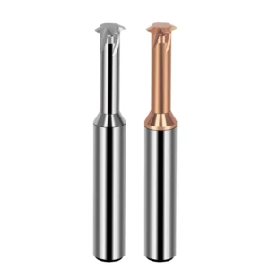
Flute Count and Chatter Suppression: Practical Synergy Between Thread Mill Flute Count and Flute Spacing
Many machinists encounter this scenario when hard-milling threads: cutting parameters look perfect and air blast is on, yet the thread walls develop dense chatter ripples. Consequently, the thread gauge binds or stops short. Operators often blame machine spindle wear or tool holder runout. Under 50x magnification, the real culprit is microsecond harmonic resonance.
Every tooth engagement sends a forced vibration shock through the hardened workpiece. Symmetric flute spacing creates an acoustic rhythm, causing discrete micro-vibrations to superimpose into severe regenerative chatter. In our tooling setups, we tightly link thread mill flute count with asymmetric spacing geometry. Introducing phase shifts disrupts natural frequencies, forcing cutting forces to cancel out before chatter starts.
Small-Diameter Deep Holes vs. Shallow Holes: Practical Selection of Thread Mill Flute Count
Never follow rigid rules like “more flutes mean higher productivity.” We once helped a medical bone-screw mold maker threading deep M4×0.7 blind holes. They tried a 5-flute cutter to increase table feed, but the tool snapped whenever reach exceeded 3×D. On a 4 mm cutter, five flutes consume too much core mass and choke chip pockets, causing fine debris to weld instantly.
Hole depth and tool reach dictate the right thread mill flute count. For deep holes exceeding 2.5×D, we select 3-flute configurations to secure thick web cores and open chip evacuation paths. For shallow holes under 1.5×D or large diameters like M10 and up, we run 4 or 5 flutes. This spreads cutting pressure across multiple teeth, extending tool life without risking catastrophic deflection.
Eliminating High-Frequency Chatter in Hard Materials: Variable Thread Mill Flute Spacing Design
Look closely at our most stable solid carbide thread mills for HRC 60+ applications: the flutes are never spaced at identical 90° or 120° angles. In brittle, high-hardness metals with near-zero plasticity, symmetric spacing acts like a tuning fork. If your cutting speed drifts into the resonance window, micro-chipping ruins the tooth profile in milliseconds.
We eliminate this issue by grinding unequal index angles directly into the flute profile. Engineered thread mill flute spacing uses a non-uniform pattern, such as 87°–93°–88°–92° on a 4-flute tool. This geometry breaks the rhythm of cutting impacts. Shockwaves from one tooth are interrupted by the next out-of-phase flute before standing waves can build up, damping chatter at the physical source.
Comparison of Actual Cutting Force Fluctuations: Testing Unequal Flute Spacing on HRC62 Material
To prove this to our North American and European clients, we ran dynamometer tests on a 5-axis machining center. We milled HRC 62 D2 tool steel (1.2379) at 35 m/min and 0.015 mm chip load per tooth. Sensor logs showed the standard equal-spaced cutter generated severe sawtooth spikes in radial forces, producing sharp chatter peaks at 4.2 kHz.
When we switched to the variable-pitch tool, peak-to-valley radial force swings dropped by almost 40%. The machined threads showed zero visible micro-fluting, and the cutting edges were spared from high-frequency impact cycles. When milling hardened steels, smoothing cutting force transitions does far more to preserve fragile carbide tips than simply bulking up static rigidity.
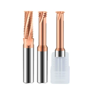
Strengthening the Micro-Scale Cutting Edge: Thread Mill Cutting Edge Strength and Geometry Control
Under a microscope, hard-milling wear patterns show a harsh physical reality. Above HRC 60, regular chip shear gives way to extreme compressive extrusion and micro-spalling. Cutting-zone temperatures easily top 800°C under punishing contact pressures. Without proper edge prep, even the best PVD coating becomes a brittle shell that flakes off the carbide substrate.
We never send tools into hardened steel with an unconditioned, raw cutting edge. To safeguard the cutter, you must reshape how stresses distribute within the first 30 microns of the profile. By tailoring edge micro-geometry, we redirect destructive shear forces away from the thin tip and down into the tool core. This mechanical approach maximizes thread mill cutting edge strength down to the carbide grain level.
Dispelling the Myth That “Sharper Is Better”: Thread Mill Cutting Edge Strength Relies on a T-Land
Machinists used to cutting stainless or titanium often assume a razor-sharp edge cuts easiest in hardened steel. Some shops even request zero-radius grinds for better finish. We learned this the hard way on HRC 63 Caldie stamping inserts in Sweden. Relying on a standard 0.015 mm honed edge caused the tool tip to chip after just two thread passes.
Simple circular honing creates excessive rubbing and heat without reinforcing the tip. Instead, durable thread mill cutting edge strength comes from grinding a true micro-negative land (T-land). We grind a 0.03–0.05 mm wide land at a -15° to -20° angle on the rake edge. This tiny bevel acts like an anvil under the tip, channeling initial contact shocks into the solid core when hitting hard carbide pockets.
Insights on Fine-Tuning Rake and Relief Angles for HRC 60–65 Hard Milling
Balancing rake and relief angles on hardened steel tooling requires careful trade-offs. While regular steels run 6° to 10° positive rake angles, high hardness demands the opposite. Any positive rake angle weakens the tooth wedge profile, causing rapid plastic deformation. In production, we set the radial rake to a negative -2° to -6° range.
Compensating the primary relief angle is equally critical. Go too steep, and you undercut the structural support beneath the cutting edge, inducing micro-chipping. Drop it too low, and the flank heavily rubs the work-hardened minor diameter during helical passes. We maintain a primary relief of 6° to 8° backed by a narrow secondary drop, balancing wedge strength against tool clearance.
Addressing Elastic Rebound: Flute Geometry That Prevents Margin Rubbing on Hardened Layers
Many shops overlook microscopic springback when milling ultra-hard tool steels. At chip thicknesses of just a few microns, high-pressure metal does not shear away completely; a portion compresses elastically and rebounds behind the pass. If your tool retains a standard cylindrical margin, this rebounding material acts like grinding compound against the tool body.
We resolve this by grinding an eccentric relief or narrow back-taper right behind the cutting edge, virtually eliminating flat circular margins. The outer cutting corner makes instant contact and immediately clears out of the cut. This geometry stops the hardened layer from dragging on the tool walls, slashing frictional heat and eliminating pitch diameter taper at the bottom of blind holes.
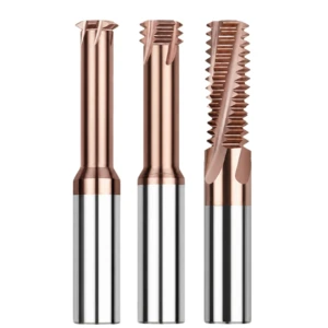
Chip Evacuation Dynamics in Micro-Flutes: Challenges and Internal Coolant Layout
Many machinists assume that because milling HRC 60+ steel yields fine dust rather than continuous ribbons, chip removal takes care of itself. In our tooling lab, shelves of snapped cutters tell a different story. At 60+ Rockwell, microscopic chips act like diamond abrasive slurry. Trapped in a tight bore, they pack tightly and destroy the cutting teeth.
High rotational speeds and tight radial clearances create turbulent boundary layers inside the hole. Without targeted flushing force, centrifugal action pins scorching debris directly against the flute walls. Reliable thread mill chip evacuation cannot be solved by simply cranking up flood coolant pressure. It requires treating the flute geometry and coolant flow vector as one unified fluid-dynamics system.
Chip Evacuation in Small-Diameter Blind-Hole Thread Milling: Powder Crushing Risks
If you have ever milled blind-hole threads with zero bottom clearance, you know the muffled thud that signals a broken tool. We investigated this on an M5×0.8 job in HRC 61 die steel for a European mold shop. Under high magnification, the cutter teeth had not snapped from bending overload; dense clusters of hardened micro-chips were pressure-welded directly across the rake face.
In a blind hole, escaping chips have only milliseconds to exit. If hot chips dwell in the pocket, subsequent tooth passes trap and crush them against the hole bottom. This turns the flute into a micro-crusher, cold-welding powder under 700°C friction and fracturing the edge. Dedicated thread mill chip evacuation must prevent chip recirculation and secondary crushing at all costs.
Measured Improvements in Chip Evacuation Efficiency Using Radial Coolant Outlets
Standard straight-through axial coolant often fails in holes deeper than 2×D. High-pressure air or oil blasts straight against the flat hole bottom, creating turbulent backpressure. This upward turbulence pushes swarf backward, straight into the path of rotating teeth. High-speed video shows chips swirling trapped in the cut zone instead of escaping out the top.
To stop this backflow, we place radial coolant ports directly into the flute valleys behind each tooth. These microscopic ports aim a 20–40 bar air-oil blast at a downward angle across the cutting face. The jet blows chips up and out along the flutes the instant they form. Shop trials show this design drops chip dwell time by over 60% while clearing frictional heat immediately.
The Role of Flute-Bottom Surface Roughness and Nano-Coatings in Mitigating Adhesive Wear
Macro flow channels are only half the battle; microscopic flute texture determines sliding resistance. Standard grinding wheels leave tiny striations across the flute core, perpendicular to chip flow. In high-hardness milling, these grinding marks act like microscopic speed bumps. Hot chips drag across these rough grooves, causing micro-welding that chokes the channel.
We solve this by mirror-polishing flute floors to under Ra 0.1 μm and micro-blasting before and after coating. Paired with low-friction, silicon-doped nanocomposite coatings, the flute acts like a high-hardness slide. Even during dry cuts or minimum quantity lubrication (MQL), this finish shields your setup from adhesive wear while promoting continuous thread mill chip evacuation.
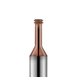
Shop-Floor Process and Failure Control: Extending HRC65 Thread Milling Cutter Tool Life
In extreme hard-milling, tool performance is measured by process consistency across dozens of parts, not just completing a single hole. Operators often pull a failed cutter and say the edge simply wore out. However, under an optical microscope, true uniform flank wear is exceptionally rare. Instead, you see micro-chipping, thermal stress cracks, and broken crest profiles.
Premature failures point back to the core flute geometry rules we established earlier. A thin core invites chatter, uniform spacing amplifies harmonics, and unpolished flutes trigger chip packing. When running an HRC65 thread milling cutter, high cutting pressures turn any micro-flaw into tool failure. Maximizing tool life demands matching micro-geometry to rigid, well-planned toolpaths.
The Primary Killers of HRC65 Thread Milling Cutter Tool Life: Mechanical Spalling and Crater Wear
On hardened production lines, the main threat to HRC65 thread milling cutter tool life is thermal-mechanical spalling rather than standard abrasion. Interrupted milling hammers the edge with gigapascals of alternating shock, followed by instant unloading in open air. This thermal cycle seeds perpendicular micro-cracks along the cutting face within minutes.
High-pressure chip sliding also creates chemical diffusion wear, washing out microscopic craters just behind the T-land. Once that crater reaches the edge, the wedge foundation collapses, breaking off the tooth. If you face sudden breakage, inspect the rake face under 50x magnification to measure crater depth. Then, widen your negative land and aim high-pressure air blast directly at the tooth face to stop cracks cold.
Matching Radial Engagement with Entry/Exit Radii to Prevent Early Chipping
Macro toolpaths dictate micro-edge survival. Many programmers still use standard linear entries, plunging straight into the hardened surface along a straight vector. In 60+ HRC steels, that sudden radial engagement spikes cutting forces instantly. That impact delivers a full-load shock to fragile carbide within a millisecond, causing the familiar dull clunk of a chipped tooth.
To stop entry shock, program a smooth 90° or 180° helical roll-in using cycloidal interpolation. If you see chipping right at the thread start, verify your lead-in arc radius equals at least 1.5 times the cutter diameter. Combine this with multi-pass radial depths, allowing the cutter to roll in with feather-light chip loads to build up compressive tool stress safely.
Reverse-Engineering Failed Samples: Geometry Compensation for Western Machine Shops
Working with aerospace and automotive tooling facilities across North America and Europe, we have built an extensive library of failed HRC65 thread milling cutter samples. Chipped tooth tips in deep blind holes point directly to jammed chips and poor flushing. Breakage occurring on the third thread pass typically reveals harmonic resonance from long tool overhangs and symmetric flute pitch.
We use this empirical data to tailor custom flute geometry for demanding applications. If your shop fights pitch diameter drift or irregular tool life in CPM 10V, Vanadis, or hardened D2, examine your speeds, feeds, tool extension, and flute counts together. If you are struggling with a tricky part right now, send over your prints and material specs. Adjusting flute spacing by just a few degrees or refining the core web often transforms a brittle process into a reliable production run.






