


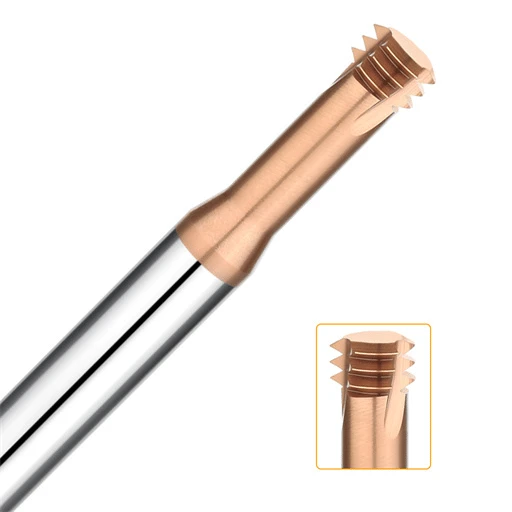
Last month, we helped a German mold shop set up tooling for hot-work tool steel (1.2379/D2 hardened to HRC 64–65). The shop supervisor slammed three broken M4 thread mills onto the workbench. The thread depth was under 2xD, yet heavy chatter marks covered every thread flank. A thread gage check revealed severe pitch diameter taper at the bottom, and tools consistently snapped before finishing the third hole. Dropping the RPM, cranking coolant pressure, and splitting cuts from three to six passes failed to stop the chipping.
We have seen this failure mode countless times over the past 16 years supporting high-precision European and US shops. Most field engineers immediately tweak feeds and speeds or demand higher-heat coatings, but they miss the core physical culprit: the geometric match between the thread mill core diameter and overall thread mill rigidity. When cutting HRC65 steel near carbide’s deflection limit, any microscopic runout ruins the tool:
-
Core too thin: While flute space is generous, high radial cutting forces cause a small diameter thread mill to deflect elastically. This triggers severe thread mill chatter and chips the carbide edge.
-
Core too thick: Bending resistance jumps, but fine hardened chips cannot escape the cramped flutes. This causes catastrophic chip packing, quickly fracturing the HRC65 thread milling tool.
Threading hardened steel is not just about choosing an advanced coating or carbide grade. It demands a delicate balance among chip clearance, thread profile height, web ratio, and tool overhang. That mechanical balance dictates whether your hardened steel thread mill delivers reliable, extended HRC65 thread mill tool life or leaves operators watching the spindle load meter in fear.
When running a long neck thread mill in HRC65 tool steel, do you know your tool’s true dynamic rigidity? Are you shearing chips cleanly, or is that carbide edge merely rubbing against work-hardened material?
Why Is Core Diameter the Primary Line of Defense in HRC65 Hardened Steel?
At HRC65, cutting mechanics change completely from conventional chip shearing to continuous micro-pulverization under extreme tool pressure. Cold-work steels and powder-metallurgy alloys show minimal plastic deformation, pushing unit cutting forces to the limit. If your cutter lacks adequate cross-sectional mass, instantaneous radial forces kick the tool backward. This immediately distorts the programmed helical path during the very first thread revolution.
In our failure analysis records, over 70% of ultra-hard milling failures stem from poor cross-sectional geometry rather than bad coatings. Many machinists assume high-toughness carbide grades alone will survive the cut. However, beam deflection formulas never lie: bending stiffness scales with the fourth power of the thread mill core diameter. If that inner solid post is too weak, the tool deflects like a reed, and the micro-honed cutting edge shatters in milliseconds.
Deflection and Thread Half-Angle Distortion: Overhang Limits Measured On-Site
We recently solved a tough threading issue for a North American medical device manufacturer running hard stainless implants. CMM inspections revealed a frustrating trend: thread entry passed inspection perfectly, but the thread half-angle showed irreversible linear drift toward the bottom. When tool overhang exceeded 3.5xD, radial cutting forces pushed the tool tip out of line by more than 12 microns.
This radial displacement forces the tool to cut off-axis, rubbing the flanks instead of shearing squarely along the normal vector. The 60-degree thread profile becomes asymmetrical, causing the Go gage to bind halfway down the hole. In hard milling, even minor deflection turns the effective clearance angle negative, inducing severe work-hardening and thread mill chatter. When reaching these overhang limits, lowering feed rates rarely helps; you must beef up the neck transition to stop the deflection chain.
The Critical Trade-off Between Chip Flute Cross-Section and Rigidity
Engineering tools for hard milling requires an uncompromising trade-off between cross-sectional steel mass and chip evacuation volume. The fastest way to increase thread mill rigidity is to shallow out the flutes, which adds solid core area. However, solid carbide is not an infinite spring; eliminating flute space chokes off the evacuation path for hot, abrasive chips. In blind internal threads, trapped dust-like chips quickly cause destructive tool rubbing.
In our cutting tests, cutters with undersized flutes snap with distinct failure patterns: heavy chip welding, metal pickup, and instantaneous torsional shear. At HRC65, trapped micro-chips cause cutting resistance to spike wildly within a single tooth engagement, instantly exceeding tool torsional limits. To counter this, we design shallow, open flutes ground with large blended radii. This preserves high bending stiffness while providing a clean aerodynamic path for high-pressure air blast.
Core-to-Diameter Ratios for HRC65 Thread Milling Tools: 45% vs 60% Web Thickness
This balance drives our core-ratio selection when specifying a dedicated HRC65 thread milling tool for high-volume manufacturing. Field testing shows that standard 45% core ratios—common on general-purpose cutters—consistently fail in materials above HRC60 due to high-frequency harmonic deflection. Bumping the core thickness to 60% drastically stiffens the tool body, but it leaves minimal space for chip flow, demanding high-pressure through-spindle air blast to keep the cut clear.
We recommend selecting your web ratio based strictly on thread pitch and thread depth. For through-holes or short thread depths under 1.5xD, choose a rigid 58% to 60% core to ensure chatter-free runs and tight pitch accuracy. For blind holes deeper than 2xD with fine pitches, back down to a balanced 50% to 52% core with multi-pass radial stepovers. This split-cut strategy prevents catastrophic breakage from packed chips while preserving tool life.

Eliminating Thread Milling Chatter in Hardened Steel: How Tool Core Rigidity Suppresses Micro-Runout
The piercing screech from a machine enclosure is rarely just a bad RPM setting. In reality, the cutting edge is succumbing to uncontrolled thread mill chatter at the microscopic level. When cutting HRC65 steel, even micron-scale vibration subjects the carbide to destructive cyclical fatigue. Instead of shearing chips cleanly, the teeth chop violently against the work-hardened surface, forcing cutting loads onto a single tooth tip and propagating micro-cracks along substrate grain boundaries.
Our testing and electron microscopy prove that dynamic runout suppression depends directly on the cutter’s mass distribution and polar moment of inertia. Without sufficient static stiffness along the shank core, the cutting edge will bounce like a washboard over the hardened microstructure—even if your spindle is balanced to G0.4. A dense, solid internal core absorbs high radial rebound forces, keeping dynamic deflection within the carbide’s elastic recovery range to stop harmonic resonance before it multiplies.
Avoiding Resonance Zones: Chatter Resistance of High-Rigidity Core Designs at Micron-Level Feed per Tooth (fz)
In hard machining, chip load per tooth (fz) is often compressed to an ultra-fine 0.005–0.015 mm range. At these micro-feeds, the honed edge radius rubs and burnishes the material under high pressure. If the tool body lacks sufficient cross-sectional stiffness, the cutting edge skitters erratically between cutting and sliding. This creates massive cutting force spikes that instantly drive the setup into the resonant frequency band shared by the machine and workpiece.
Do not assume dialing back the feed rate will save the tool. When machine rigidity allows, slightly increasing the chip load forces the cutting edge to bite cleanly past the work-hardened surface layer. However, this strategy only works if your hardened steel thread mill possesses the solid core mass required to resist severe tangential forces. Balancing a reinforced core with an intentional, decisive micro-feed prevents cutting-edge deflection and keeps the tool safely outside catastrophic resonance zones.
How Unequal Tooth Spacing and Variable Helix Angles Synergistically Enhance Vibration Resistance
Simply thickening the solid cross-section yields diminishing returns, especially in long-reach setups where symmetrical cutting edges generate repetitive impact frequencies. We implement unequal circumferential flute spacing and variable helix angles to disrupt this harmonic cycle through geometric asymmetry. By offsetting tooth engagement timing by mere microseconds, the cutting forces cannot align into stationary resonant waves inside the tool body.
However, an asymmetric flute geometry requires tighter control of structural integrity during tool grinding. Uneven flute spacing creates non-uniform cross-sections along the tool body, where poorly blended flute transitions can turn variable-helix lateral forces into severe stress risers. We grind compound, variable-radius blending curves at the base of every flute. This design guarantees consistent torsional modulus across every axial section, ensuring that anti-vibration fluting reinforces thread mill rigidity rather than compromising structural strength.
Shop-Floor Case Study: A Workholding and Tooling Setup That Cut Surface Roughness and Chipping by 60%
A North American tier-one die maker struggled to machine M6 fine-pitch internal threads in Cr12MoV stamping inserts (HRC 63–65). Thread flanks showed heavy transverse chatter marks, and every long neck thread mill chipped within two holes. Our on-site audit found two compounding issues: the cutter core lacked adequate sectional mass, and their ER collet chucks ran out by more than 8 microns—pushing the setup into severe chatter.
We replaced the tools with an unequal-flute, reinforced-core design and switched the workholding to precision hydraulic and shrink-fit toolholders, clamping total runout under 3 microns. The microscopic ripple marks vanished immediately, leaving a near-mirror surface finish. Edge wear shifted from brittle chipping to predictable, slow flank wear. Overall tool chipping plummeted by over 60%, delivering reliable, lights-out threading across entire production shifts.
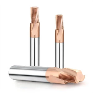
Practical Core Thickness Design for Small Diameter, Long Neck Thread Mills
Threading deep blind holes smaller than M3 in ultra-hard tool steels is one of the most unforgiving tasks in precision machining. When the cutting diameter shrinks to 2–3 mm, cross-sectional safety margins disappear, making traditional design rules obsolete. Radial cutting resistance does not drop proportionally with cutter size in HRC65 materials. Consequently, mechanical stress on a small diameter thread mill core spikes dramatically, and any unbalanced load causes immediate brittle failure.
When engineering micro-thread mills for precision connector molds and aerospace valves, torque transmission efficiency within sub-millimeter envelopes is our main priority. Standard flute geometries cannot be scaled down proportionally because chip evacuation resistance and edge-hone squeezing effects change drastically at the micro scale. We re-engineer the back-spine profile to balance shallow chip troughs against rigid support ribs, allowing the tool to resist heavy side-thrust while evacuating fine debris.
Deep-Hole and Long-Overhang (L/D > 3) Applications: Compensating for Rigidity via Tapered Necks
When thread depth exceeds 3xD or 4xD, standard straight-neck tools quickly cross into the failure zone. Under long overhangs, tool-tip deflection increases with the cube of the extended length. Even on rigid spindles, standard shanks experience microscopic bending and high-frequency spring-back. For these long-reach operations, we grind a continuous back-taper or reinforced stepped neck, creating a rigid conical foundation that bridges the clamping shank directly to the cutting head.
When running tapered-neck tools on the shop floor, verify clearance boundaries against the hole entrance chamfer. Programmers sometimes call out overly aggressive taper angles in search of stiffness, only to have the reinforced neck rub or gouge the hole rim during helical interpolation. We recommend a safe radial clearance margin of 0.08 to 0.15 mm. Maximizing neck thickness up to that exact interference boundary provides the highest possible dynamic stability without risking an edge collision.
Preventing Fatigue Fractures: Optimizing Root Transition Radii in Small Diameter Thread Mills
Inspection of broken micro thread mills confirms that shanks rarely fracture midway through the flutes; failure occurs almost exclusively at the junction where the cutting teeth meet the neck. This transition zone experiences the highest combined bending moments and torsional peaks. If grinding leaves sharp steps or microscopic wheel scoring, cyclical impact shock from HRC65 steel drives micro-cracks rapidly through the solid carbide substrate.
We eliminate this failure mode by grinding smooth, multi-radius blended transitions (R-transitions) between the teeth roots and clearance neck, removing sharp geometric transitions. However, this blend must not encroach on full thread depth clearance. A blend radius ground too large will rub against the major thread diameter at the bottom of the hole, creating intense frictional heat. Balancing clearance tolerances down to tens of microns keeps high-load thread mills safe from premature fatigue fracture.
Orbital Tool Paths and Radial Depth of Cut Strategies for Long Neck Thread Mills in Deep Cavities
Deep cavities in HRC65 steel cannot tolerate the aggressive, single-pass orbital tool paths often used on softer alloys. Hardened tool steel offers no plastic give; a single full-depth pass generates immense radial cutting force that pushes an extended-reach cutter off-axis. This causes severe pitch diameter taper and out-of-round threads. Instead, we program multiple radial stepover passes to divide cutting loads into controlled increments that stay well within the tool’s elastic limit.
However, you must never make the finishing pass too light. Machinists often drop the final radial cut (ae) below 0.002 mm to protect the tool, but this backfires: the edge rubs and burnishes the hardened material instead of shearing chips, stripping the coating and work-hardening the workpiece. For consistent HRC65 thread mill tool life, keep the radial depth of your final pass at 1.5 to 2 times the cutting-edge hone radius. Combined with tangential arc-in and arc-out lead moves, this approach ensures clean shearing and stops taper caused by tool deflection.
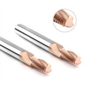
Realizing Tool Life for Hardened Steel (HRC65 Thread Mill): A Closed-Loop Match of Substrate, Coating, and Core Rigidity
Machinists often ask us why expensive nano-coated tools still chip prematurely in hardened tool steels. The breakdown occurs when engineers treat coating hardness and core rigidity as separate variables. A microscopic coating layer cannot survive without structural backing from the carbide core underneath. If body deflection exceeds the lattice elasticity of the coating, even a 4000 HV surface will delaminate and fracture in seconds, cutting short your expected HRC65 thread mill tool life.
Maximum endurance demands a closed-loop balance among the carbide substrate, surface coating, and cross-sectional geometry. A rigid core limits dynamic deflection, keeping forces on the honed edge land within controllable limits. This dynamic stability lets high-heat coatings work effectively within their optimal red-hardness zone. Ignoring internal core cross-sections while focusing solely on coating grade inevitably leads to catastrophic, brittle fracture the moment the tool enters the cut.
Ultra-Fine Carbide Substrate and Impact-Bearing Capacity of the Core Cross-Section
Selecting carbide grades for HRC65 often triggers a common misconception: that harder, finer grain structures are always better. Sub-micron grains (0.2–0.4 μm) with low cobalt maximize resistance to plastic deformation, but they also lower fracture toughness (KIC). If the thread mill core diameter is undersized, intense bending stresses consume that limited toughness quickly. Hitting a coarse carbide hard spot in the workpiece then causes instant micro-cleavage failure.
We select sintered carbide grades with a minimum transverse rupture strength (TRS) of 4200 MPa to guarantee a safety buffer. That tough matrix requires a substantial solid core cross-section to absorb the mechanical shock pulses generated during helical entry. If broken tools display flat, mirror-like fracture surfaces, step back and re-evaluate your core-to-overhang ratio. Adding cross-sectional mass absorbs impact shock far better than merely backing off the feed rate.
Documented Wear Patterns of High-Temperature Oxidation-Resistant Coatings on Rigid Tool Bodies
Under scanning electron microscopy, worn cutting edges from HRC65 runs reveal vastly different wear modes depending on tool core stiffness. Supported by a rigid core, AlTiN or AlTiSiN nanocomposite coatings easily handle cutting zone temperatures above 900°C. They generate an ultra-dense aluminum oxide passivation layer, yielding smooth, uniform flank wear. Conversely, a flexible tool core flexes cyclically, causing the brittle coating to crack perpendicular to the cutting edge and peel off rapidly.
We see this cause-and-effect relationship regularly during on-site shop audits. While silicon- and chromium-doped coatings provide extreme oxidation resistance, their mechanical ductility is essentially zero. To run an effective HRC65 thread milling tool, a rigid core is non-negotiable to hold the cutting edge on its true toolpath. Preventing core deflection keeps alternating cyclic stresses from shattering the coating, protecting the underlying carbide from severe thermal degradation.
On-Site Process Strategies to Extend Single-Tooth Tool Life: Up-Milling, Multi-Pass Layering, and Air Cooling
For cutting kinematics, we strongly recommend switching from conventional climb milling to up-milling in HRC65 steels. Climb milling enters at maximum chip thickness, slamming the cutting edge directly into the glass-hard surface and chipping the honed land. Up-milling starts at zero chip thickness, ramping cutting forces up smoothly. This upward force seats a rigid hardened steel thread mill securely against its toolpath, dampening micro-vibrations and substantially extending tool life.
Coolant strategy is equally critical for tool survival. Flood coolant must be strictly avoided during hard thread milling. Interrupted cuts inside a semi-enclosed hole subject hot cutting teeth to dozens of thermal shock cycles per second, causing severe thermal fatigue cracks. Run high-pressure dry air at 6 bar or higher instead. The goal is not liquid cooling, but high-velocity chip evacuation that stops abrasive, hot dust from being re-cut.
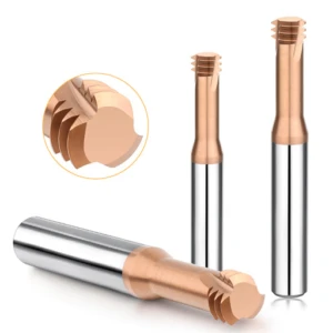
Field Guide to Thread Mill Cutter Selection, Setup, and Troubleshooting
When threading HRC65 parts, the most expensive mistake is adjusting speeds and feeds blindly after a failure occurs. Successful threading depends on a rigid chain: machine spindle health, holder runout, overhang ratio, and cutter core mass. The weakest link in that chain always breaks first in hardened materials. Reliable thread mill cutter troubleshooting requires tracing cutting forces backward through the tool body to identify where deflection, heat, or chip packing caused the failure.
Before blaming CNC positioning accuracy or part programming for out-of-spec threads, inspect the physical failure signatures. Did the overhang ratio push past the tool’s elastic limit? Are micro-chips getting trapped in the flutes? Is the core flexing under micro-feed loads? Evaluating your setup through this mechanical lens will resolve most threading bottlenecks in minutes rather than days.
Go/No-Go Gauge Inspection: Field Corrections for Pitch Taper Errors Caused by Tool Deflection
Thread plug gauges provide immediate insight into dynamic tool deflection. The most common defect in deep holes is a Go gauge that fits the hole entrance smoothly but binds near the bottom. This false taper happens because the cantilevered tool tip deflects away from the cut under radial pressure. Because rigidity is lowest at the free end, actual pitch diameter shrinks progressively toward the hole bottom, leaving an undersized thread profile.
If your Go gauge binds at the bottom of a deep thread, apply a stepped radial compensation program. Adding a progressive radial offset of 0.005 to 0.010 mm exclusively to the deep segment compensates directly for mechanical deflection. If pitch taper persists, choke up on the tool holder to reduce overhang, or run a final zero-depth spring pass using up-milling. Utilizing directional cutting forces to stabilize the tool is far more effective than changing global offset values.
Troubleshooting Core Thickness: Chipping from Chip Packing vs Insufficient Rigidity
Inspecting a damaged cutting edge under magnification clarifies whether a failure stemmed from chip packing or low tool rigidity. If chipping is concentrated along the outer tooth crests—accompanied by chatter marks on the thread flanks—the culprit is dynamic vibration from insufficient thread mill rigidity. However, if you find metal buildup, smeared chips welded inside the flutes, or a tooth sheared from the flute pocket, the tool choked on trapped chips.
If you are threading blind holes and find welded chips inside the flutes, open up your flute geometry to prioritize chip clearance over extreme core thickness. If you see micro-chipping on extended-reach setups, switch to a thick-core design with unequal flute spacing to suppress chatter. Every machining setup involves unique machine dynamics, workholding stability, and air delivery. If you are battling tough thread tolerances or premature tool failure, sharing your workpiece prints, hardness specs, and toolpaths allows us to calculate exact cutting force models for your application.






