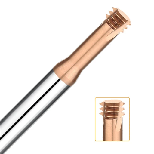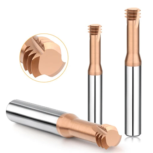
Last month, a precision injection mold client in Stuttgart sent us urgent SEM images of broken cutting edges. They had snapped two imported coated thread mills back-to-back in an M6×1.0 blind hole. The workpiece was a core slide made of Vanadis 4 Extra cold-work powder steel, hardened to 64–65 HRC. The setup tech had switched to a 4-flute cutter to cut cycle times. Instead, the tool emitted a high-pitch whistle on the second thread pass and fractured instantly at the hole bottom, risking a mold insert worth over ten thousand dollars.
This is a recurring problem we have tackled for 16 years across European and American machine shops. Once steel crosses the 60 HRC mark, cutting forces climb exponentially, and minor tool imbalances cause immediate failures. When cutting hardened tool steels, process engineers regularly debate whether to run a 3-flute vs 4-flute thread mill.
The instinct is to grab a 4-flute carbide thread mill for its thick core and high bending stiffness to fight deflection. However, at 65 HRC, chips break into abrasive micro-powder that easily chokes narrow flutes. Once that path clogs, the open gullet of a 3-flute carbide thread mill becomes a lifesaver. Selecting the wrong geometry causes rapid flank wear, pitch errors, or catastrophic tool fractures.
As toolmakers testing substrates and coatings on dynamometers daily, we know this is never a simple trade-off between stiffness and pocket size. Choosing a carbide thread mill for hardened steel requires balancing single-tooth loads, edge speeds, coating fatigue, and evacuation. Has your shop ever scrapped an expensive HRC65 insert by chasing cycle times with the wrong flute count?
Why is there zero margin for error when selecting the number of flutes for thread mills used on HRC 65 hardened steel?
Machinists often tweak feeds and speeds on the fly when roughing soft materials. However, on 65 HRC steel, choosing the wrong threadmill tooth count causes immediate, permanent damage. When cutting pre-hardened steels (30–40 HRC), the workpiece retains sufficient ductility to forgive minor setup errors. You might get minor chatter or a rough finish, but the tool survives.
At 65 HRC, the alloy lattice consists entirely of dense tempered martensite and hard carbides. Yield strength is extreme, and elongation drops near zero. Every tooth engagement acts like an impact hammer strike on the carbide substrate. Too many flutes restrict chip pocket volume, causing fatal chip packing. Too few flutes leave the tool core too thin, causing instant radial push-off and edge fracture.
Extreme Mechanical Stress and Thermal Shock Faced by Thread Tools at 65 HRC Hardness
At 65 HRC, cutting mechanics shift entirely away from typical shear-plane plastic flow. Our dynamometer data shows unit cutting forces spike to more than three times those of standard AISI 1045 carbon steel. Because hardened tool steel conducts heat poorly, friction concentrates heavily at the cutting zone. Contact temperatures rapidly shoot past 800°C, dumping extreme heat directly back into the cutting edge.
These physics push standard thread tools straight to their structural breaking point. The tool must resist massive radial loads while handling intense thermal shock every few milliseconds during helical entry. Without balanced core support, stresses localize along the tool flank. Micro-cracks quickly form along the coating substrate boundary, triggering rapid conchoidal spalling that strips the cutting tip bare.
A Common Lesson from North American and European Shop Floors: Applying “Standard Steel” Tooling Habits to High-Hardness Steel Machining
During site visits across North America and Europe, we frequently catch programmers falling into the “more flutes equal higher table feed” trap. One automotive stamping shop in Detroit applied their standard alloy steel (AISI 5140) parameters to D2 tool steel hardened to 64–65 HRC. They chose a 4 flute carbide thread mill for deep blind holes, assuming that extra flutes would automatically reduce overall cycle times.
The tool snapped on the second thread turn. Powdered, abrasive chips packed the narrow flutes at the blind bottom, creating a torsional wedge that snapped the cutter shank. High-flute tools work wonders in structural steel, but chip evacuation dictates survival in 65 HRC blind holes. Gaining theoretical rigidity by adding a flute means nothing if it chokes the chip exit path and destroys the tool.
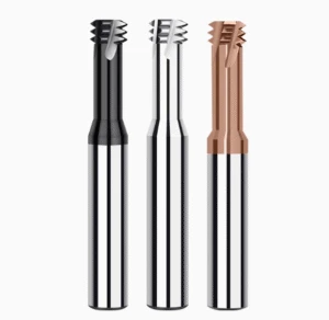
Core Structural Comparison: 3-Flute vs 4-Flute Thread Mills—Balancing Mechanics and Chip Evacuation in High-Hardness Steel
Grinding wheel profiles enforce strict geometric limits: cross-sectional core area and chip gullet volume exist in a direct zero-sum balance. This structural trade-off dominates the 3 flute vs 4 flute thread mill selection. A 4-flute geometry sacrifices gullet width to maximize web thickness and bending resistance. Conversely, a 3-flute design thins the center core to open more than 30% additional room for chip clearance.
Machinists often fall into the trap of treating rigidity as the only metric that matters. At 65 HRC, low core strength causes immediate microscopic tool push-off during helical engagement. Yet over-prioritizing rigidity shrinks the gullets until fine, hardened debris packs tightly between the teeth. Understanding this geometric compromise prevents premature catastrophic edge fracture.
Key Advantage of 4-Flute Carbide Thread Mills: Superior Rigidity Against Deflection Driven by a Large Core Diameter
In shallow threading where rigidity controls size, a 4 flute carbide thread mill holds a decisive structural edge. Cantilever beam deflection formulas show that bending stiffness scales with the fourth power of the tool core diameter. We typically grind our 4-flute cutters with a 60% to 65% core-to-diameter ratio. This massive moment of inertia restricts elastic cutting deflection to the single-digit micron range.
For through-holes and shallow blind holes under 1.5D, this thick web yields unmatched process stability. In our die-repair trials on hardened tool steels, 4-flute cutters maintained exact pitch diameters and flank angles through dozens of parts without taper. When chip clearance is not constrained, high torsional stiffness effectively suppresses chatter and holds tight thread tolerances.
The Irreplaceability of 3-Flute Carbide Thread Mills: Thread Mill Chip Evacuation in Deep Holes and Small Blind Holes
When threading depths push past 2D or 2.5D, a 3 flute carbide thread mill often becomes your only viable option. Chips from 65 HRC steel fracture into abrasive, high-friction grit rather than curled ribbons. If the gullet space is too narrow, external air blasts cannot reach the cut zone, and poor thread mill chip evacuation triggers severe chip re-cutting.
A 3-flute profile features an open 120° flute cross-section that provides an unobstructed escape path for pressurized air or oil mist. In a Swiss shop machining deep M4 blind holes in medical mold inserts, 4-flute cutters consistently snapped on bottom retraction due to packed dust. Switching to a 3-flute design with open gullets flushed the debris instantly, completely stopping the breakage.
Real-World Cutting Force Monitoring Data: The Actual Impact of Increasing Flute Count on Single-Tooth Load and Radial Deflection
Using multi-axis dynamometers on 65 HRC cold-work steel, we measured cutting forces across both geometries at identical surface speeds (Vc = 45 m/min). Adding a fourth flute distributed cyclic cut forces and smoothed instantaneous peak impact on the tips. However, because more teeth contact the material per revolution, total radial thrust increased, demanding greater machine spindle and setup rigidity.
The critical metric is radial deflection. At short overhangs under 1.5D, the 4-flute cutter showed 40% less deflection amplitude than the 3-flute tool. Past 2.5D, however, chip packing along the narrow flutes produced erratic side thrust that caused sudden force spikes and high-frequency chatter. Never evaluate tooth-load math in isolation; always factor in flute clearance and overhang ratio.
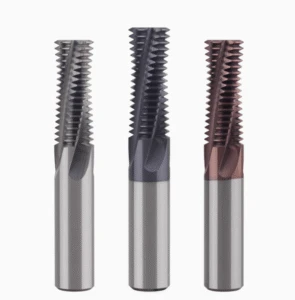
Real-World Tool Life Showdown: Thread Mill Tool Life in Hardened Mold Steel
In hard milling, tracking thread mill tool life curves matters far more than shaving three seconds off a single cycle. At 65 HRC, wear progression rarely follows a gentle linear slope; it mimics a steep bathtub curve. If an edge survives initial cyclic stress, it enters a stable, predictable wear phase. However, once micro-damage appears, complete structural failure happens within seconds.
Technicians often ask why a tool cut 40 parts smoothly last week, but a new one fractured after only 15 holes today. High-hardness substrates generate extreme abrasive friction and mechanical fatigue. Flute count directly determines thermal cycle frequency and decides whether an edge degrades through gradual flank abrasion or sudden brittle chipping.
Differences in Failure Modes for 3-Flute vs 4-Flute Tools in Hardened Steel: Micro-Chipping vs. Mechanical Flank Wear
Electron microscopy on hundreds of spent tools reveals contrasting end-of-life signatures between 3-flute and 4-flute cutters. With adequate setup rigidity, 4-flute tools usually fail via progressive mechanical flank wear. Lower individual tooth loads allow stable micro-shearing, though heat concentration gradually erodes the coating-substrate boundary until thread pitch diameters drift out of tolerance.
Conversely, 3-flute tools fail primarily through cutting edge micro-chipping. Because the core is thinner, maintaining the required chip load produces higher normal impact forces per tooth. Striking hard carbide segregations in the steel triggers intense localized shear peaks, creating micro-notches on the crests. Once a micro-chip forms, cutting forces multiply, rapidly breaking the tooth.
Handling Extreme Conditions: Coating Adhesion Performance for Carbide Thread Mill for Hardened Steel
At 65 HRC, cutting temperatures easily cross 800°C, and raw sub-micron carbide anneals rapidly without a robust thermal shield. In our shop, developing a carbide thread mill for hardened steel proved that coating adhesion under shear matters far more than room-temperature hardness values. Early high-aluminum AlTiN coatings showed high hot hardness, but steep thermal gradients caused delamination around micro-chipped edges within ten holes.
We moved to specialized cathodic-arc nanocomposite AlCrN systems that synthesize a dense corundum-phase chromium oxide (Cr2O3) boundary layer at high temperatures. This coating cuts friction by 25% and resists chemical diffusion bonding from hot iron particles. However, even advanced nano-coatings fail without consistent edge prep; missing the micro-honing target by 2 microns triggers premature edge flaking.
On-Site Tool Life Comparison: Tracking Continuous Tapping Operations on Blind Holes
In a Detroit die shop, we tracked both geometries cutting M8×1.25 blind holes 12 mm deep into DC53 steel hardened to 64–66 HRC using air blast. Running matching parameters—Vc = 40 m/min with a 3-pass radial infeed—we logged tool wear and part count across identical production batches.
The 4-flute tool reliably machined 28 to 32 holes before flank wear reached 0.12 mm and the No-Go plug gauge engaged, confirming predictable, gradual wear. The 3-flute tool showed clear flutes and zero chip packing, but a micro-impact chipped a leading tooth edge at hole 22, shifting pitch diameter abruptly. If you need tight statistical process control, 4-flute wear is easier to schedule; for deep blind holes, 3-flute chip clearance prevents catastrophic snap-offs.

Shop-Floor Machine Setup: Logic for Setting Key Thread Mill Speeds and Feeds
Whenever we visit a machine shop to troubleshoot snapped cutters, our first move is to check the feed override switch and read the active program values. In 65 HRC steel, thread mill speeds and feeds must never come straight from catalog median tables. Hard milling has a razor-thin process window: bump cutting speed (Vc) by just 5 m/min, and thermal shock strips the coating off the carbide substrate; drop feed rates too low, and the edges slide over work-hardened zones, causing severe flank rubbing and premature failure.
The core tuning principle balances heat dissipation against minimum chip thickness. Because hardened alloys resist brittle shear, each flute must take a clean bite rather than scrape. Setting spindle RPM and feed per tooth requires factoring in the number of flutes, chip evacuation resistance, and spindle dynamics. Leaving a conservative performance buffer on the machine ensures structural survival on every pass.
Calculation Differences in Cutting Speed (Vc) and Feed per Tooth (fz) for 3-Flute vs. 4-Flute Thread Mills
Programmers often make one of two mistakes: applying identical feeds to both designs, or multiplying feed by 1.33 purely based on flute ratio. In 65 HRC stock, surface speed is limited by coating thermal endurance rather than tooth count. Whether using a 3-flute or 4-flute cutter, keep baseline cutting speed strictly between 35 and 45 m/min. Never raise RPM just because you added a tooth.
The real difference lies in fine-tuning feed per tooth (fz). A 4-flute design has a thick core and high bending stiffness, handling an fz of 0.015 to 0.025 mm/tooth for clean shearing. Conversely, a 3-flute cutter has deeper gullets and reduced transverse shear strength; running it at identical chip loads causes excessive deflection on contact. We restrict 3-flute feed to 0.012–0.018 mm/tooth, prioritizing vector force stability over raw cycle time.
The Feed Compensation Pitfall in Internal Thread Circular Interpolation: Correction Formulas for Programmed vs. Actual Cutting Edge Feed
This mistake remains one of the most common CAM post-processor errors we catch in European and US shops. When writing G02 or G03 helical moves, CAM systems default to tool center path feed (Vfprog). On external threads, the center path is larger than the thread diameter, reducing load. On internal threads, the tool center radius is significantly smaller than the bore radius, which compresses the peripheral contact path and spikes cutting edge feed two to three times over programmed values.
Without geometric compensation, a programmed fz of 0.015 mm/tooth can jump past 0.04 mm/tooth at the hole wall. At 65 HRC, that overload snaps carbide tips instantly. Programmers must calibrate machine code with the center feed correction formula: multiply actual peripheral feed by the difference between minor thread diameter and tool diameter, then divide by minor diameter. This correction guarantees true micro-shearing loads at the edge.
Entry Strategy for 65 HRC Materials: Why We Recommend Only Arc Entry (Roll-in) and Radial Passes
Straight linear plunging or perpendicular lead-ins into 65 HRC steel hit brittle carbide tips like an anvil hammer. Over 30% of field failures happen on initial workpiece contact. For high-hardness work, the only entry paths we approve are smooth 90° or 180° circular roll-in moves. These arc paths transition chip load smoothly from zero to full depth, absorbing shock loads through continuous circular motion.
Single-pass full-depth cutting is an unnecessary risk in 65 HRC material. We require a 2- to 3-pass radial step-down strategy based on thread pitch: rough pass 1 removes roughly 65% of thread volume, pass 2 clears 30%, and a spring pass takes the final 5% to lock in thread geometry. Radial passes slash total deflection and allow compressed air to flush out fine grit between cuts, preventing catastrophic chip packing.

Selection Decision Guide: Diagnostic Checklist for 3-Flute vs 4-Flute Thread Mills in Production Shops
After troubleshooting dozens of shop floors, we treat cutter selection as an operational constraint audit rather than a catalog search. For hardened die steels, choosing a 3 flute vs 4 flute thread mill always comes down to balancing core stiffness against chip clearance volume. Comparing tooth counts without reviewing fixture rigidity, hole depth, and coolant delivery misses the practical constraints of the job.
If you are setting up a hard threading job, evaluate your setup before changing CAM feeds. The rigidity gains of an extra flute only pay off if chips have a clear exit path. When chip clearance hits its limit or long overhangs create chatter, stepping down to a 3-flute cutter is the most reliable way to protect your part.
The L/D Ratio Watershed: Why 4 Flutes Excel in Short Overhangs and 3 Flutes Solve Long-Reach Vibration
The primary physical check is the length-to-diameter (L/D) overhang ratio. If you are milling through-holes or shallow blind holes under 1.5D with rigid toolholding, run a 4-flute cutter. A thick core diameter gives the 4-flute design a high area moment of inertia, minimizing radial push-off and holding tight pitch diameter tolerances across short runs without leaving taper marks.
When hole depths exceed 2.0D or reach 2.5D, cantilever deflection scales cubically with overhang length, making 4-flute tools prone to severe harmonic chatter. Narrow flutes compress abrasive dust against the bore wall, generating erratic side loads. Switching to a 3-flute cutter opens wide chip gullets that release cutting pressure smoothly, dampening resonance and protecting fragile tooth tips at extended reach.
Chip Evacuation Limits at the Bottom of Blind Holes: Preventing Re-Cutting and Bottom Dead-Zone Breakage
Blind holes present the highest failure risk in hard milling. If the pre-drilled pilot hole leaves less than 1.5 pitches of clearance past the thread depth, pressurized air cannot evacuate powder from the bottom pocket. During final arc retraction, these trapped particles drag across the cutter face, causing instant edge breakage through chip re-cutting.
If drilling deeper pilot holes is impossible, switch immediately to a 3-flute cutter with high-volume thread mill chip evacuation channels. Pair this with a radial multi-pass toolpath and a single-revolution air-blow dwell at the floor before retracting. The 120° gullet gives debris room to escape rather than packing solid; if your spindle load spikes during hole-bottom retraction, your flutes are clogging.
Air Blast, MQL, and High-Pressure TSC: How Coolant Delivery Dictates Maximum Flute Count
Coolant delivery sets the hard limit on usable flute count. If your machine relies on external air nozzles or Minimum Quantity Lubrication (MQL), limit cutters to 3 flutes for threads below M8. High-speed spindle rotation creates a boundary air barrier that deflects external jets away from deep blind bottoms, leaving chip clearing entirely up to flute volume.
With high-pressure Through-Spindle Coolant (TSC) or through-tool air above 15–20 bar, you can safely run a 4 flute carbide thread mill. Axial high-pressure jets blast hard grit out through narrow flutes, neutralizing chip packing risks. If you are dealing with challenging blind holes, extreme hardness variations, or recurring breakage, share your prints and setup details with us—we will help you dial in the toolpaths and tool geometry.