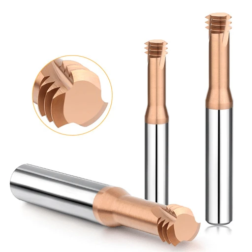
Last month, we received an urgent call from a precision mold shop in Stuttgart, Germany. They were breaking tools on the final M4×0.7 blind holes of an S136 mirror-finish mold insert hardened to HRC64–65. With production halted and tens of thousands of dollars in parts at risk, their shop manager was frustrated. They had always relied on standard full tooth thread mill cutters, which run fast on pre-hardened steels but fail quickly on extreme alloys.
As a thread mill manufacturer supporting precision shops worldwide, we see this breakdown pattern constantly. At HRC65, tool steel loses almost all ductility, causing cutting forces and friction to surge. Machine operators usually try lowering spindle speeds or chip loads first. However, the root problem is almost always tool geometry: do you run a full-profile tool in a single pass, or choose a partial profile thread mill using multi-pass helical interpolation?
When machining high-value hardened components, taking the wrong approach turns expensive inserts into scrap. Single-pass cycle times look great on paper, but the resulting radial deflection often shatters micro-grain carbide tips. Is it worth gambling an expensive workpiece on a single-pass full-profile tool, or should you switch to a multi-pass partial-profile strategy to guarantee a 100% thread gauge pass rate?
Tackling HRC65 Hardened Steel: Cutting Forces and the Tool-Breakage Threshold Observed On-Site
If you have ever milled threads above HRC60, you know the sound of a cut on the edge of failure. Last year, we troubleshot vacuum-heat-treated D2 mold inserts measuring HRC64.5 at a Detroit shop. The operator kept dropping the feed, but by the third thread turn, the hum became a dull thud, followed by an emergency stop. At this hardness, steel cannot shear plastically; cutting shifts into abrasive micro-fracturing and intense compressive crushing.
We mounted a dynamometer on the machine table and measured lateral thrust forces 3.5 times higher than in pre-hardened stock. Under these loads, even minor micro-segregation or light surface decarburization sends massive shock spikes straight through the tool shank. In the world of thread milling hardened tool steel, you cannot blindly follow generic handbook parameters. Past HRC60, material yield tolerance hits zero, and any localized load spike causes edge failure in milliseconds.
Radial Loads at Extreme Hardness: Why Full Tooth Thread Mills Frequently Suffer Micro-Chipping on HRC65 Mold Steel
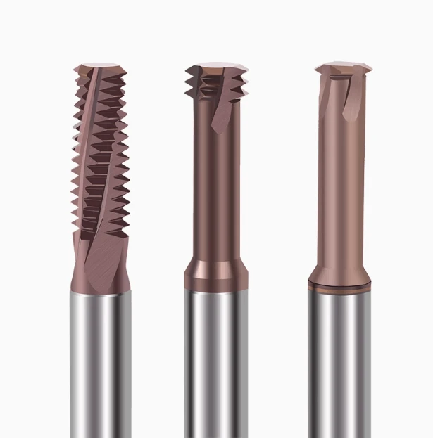
Machinists often ask us why we avoid cutting threads in one pass when cycle time is critical. The physics explain why: when a full-depth cutter engages, its entire axial cutting edge bites simultaneously. On an M6×1.0 thread, six teeth cut at the same time, expanding the tool contact arc drastically. Against an HRC65 workpiece, this forces delicate sub-micron carbide tips against a rigid wall, pushing the tool shank off-center.
This elastic deflection is where tool failure begins. Under our optical microscopes, we rarely see complete tool snap-offs; instead, we find shell-like micro-chipping along the secondary cutting edges of the leading teeth. A standard full tooth thread mill absorbs a heavy radial spike at full depth, deflecting roughly 0.01 mm. The machine’s servo loop compensates immediately, overloading the cutting edge and shattering the thin PVD coating instantly.
The Reality of Machine Rigidity: Actual Cutting Differences Between Two Types of Thread Mills on 3-Axis Machining Centers vs. 5-Axis High-Speed Machines
Machine kinematics dictate real-world tool performance, especially on difficult materials. We ran identical setups for a Swiss orthopedic customer on two different platforms: a heavy-duty 3-axis box-way machine and a high-dynamic 5-axis high-speed center. Many machinists assume heavy box-way castings cut hardened steels better due to vibration dampening. In practice, the actual cutting data proved the exact opposite.
During tight helical interpolation, backlash and servo lag on the 3-axis machine created microscopic hesitations at quadrant transitions. Even a microsecond stall in HRC65 stock pinches the carbide tip and breaks it. When evaluating precision thread tools, machine acceleration and servo tracking matter as much as base mass. If your shop runs older 3-axis machines, choose a single-tooth or reduced-contact profile to bypass servo hesitation entirely.
Common Failures in Western Workshops: Secondary Grinding and Thread Pitch Diameter Deviations Caused by Poor Chip Evacuation
Chip evacuation failures are another major source of scrap parts in production shops. Many machinists assume the fine, powdery chips from thread milling clear out easily on their own, relying only on flood coolant nozzles. We inspected M5 blind holes in HRC65 stock using a borescope and found tiny, work-hardened blue granules packed tight along the bottom. Without clear exit paths, these hard particles stay trapped in the hole.
These trapped chips cause severe secondary recutting between the thread flanks and the tool clearance relief. The “Go” gauge might feel tight, but optical comparators show the pitch diameter ballooned oversize by 0.03 mm to 0.05 mm from abrasive wear. When configuring thread cutter tool setups, high-pressure air blast clears fine chips far more reliably than liquid coolant. Proper nozzle positioning and flute clearance matter far more than tweaking feed rates by a few tenths.
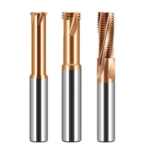
Comparison of Two Thread Mill Tooth Profiles: Mechanical and Cutting Efficiency Tests of Full Profile vs Partial Profile Thread Mills
When threading workpieces at extreme hardness levels like HRC65, process engineers face a tough call: use a full-profile tool in one pass, or take a multi-pass approach with a partial-profile tool? This is never a simple choice; it is a direct trade-off between radial cutting load and process reliability. On customer test floors, we mount both tool styles on the same machine to compare spindle load spikes and first-pass thread gauge acceptance under identical coolant and rigidity setups.
Our test data shows that crossing HRC60 fundamentally reshapes cutting mechanics. That is why choosing a full profile vs partial profile thread mill requires unlearning aluminum or pre-hardened steel habits. Multi-tooth cutters deliver concentrated, instantaneous impact shocks. In contrast, single-tooth or partial-profile tools spread that load across controlled micro-cutting cycles, protecting both the tool and the workpiece.
Contact Arc and Cutting Force Distribution: Chip Evacuation Realities for Both Thread Mill Profiles on Heat-Treated Workpieces
High-speed video and dynamometer data reveal exactly how chips behave inside hardened thread roots. When a full-profile tool reaches depth and begins helical interpolation, all cutting teeth engage at once. On HRC65 tool steel, this wide contact arc chokes off the chip exit path entirely. Trapped brittle particles cannot escape, grinding between the tool teeth and thread flanks to cause severe cold-work hardening and scuffing.
Switching to a single-tooth or three-tooth tool completely resolves this clearance issue. Because only a small portion of the profile cuts during each helical revolution, wide evacuation channels remain open. Evaluating these two thread mill profile types confirms that partial profiles allow compressed air to flush out hard chip debris instantly. Cutting force curves remain smooth and sinusoidal rather than spiking violently.
Balancing Cycle Time and Tool Life: A Real-World Comparison of Thread Milling Efficiency in Mass Production
Single-hole cycle timers make full-profile tools look deceptively fast on paper. During an M8×1.25 tooling trial for a Detroit automotive supplier, a full-profile cutter finished a thread in 8 seconds, while a partial-profile tool took 38 seconds. The plant supervisor initially favored the single-pass tool because paper estimates suggested massive throughput gains.
Extending the test to a 100-hole run revealed the true measure of thread mill cutting efficiency. The full-profile tool developed micro-chipping by hole 14, throwing pitch diameter out of tolerance and scrapping an expensive part. The partial-profile cutter ran 120 holes with zero defects and perfect gauge fit. Factoring in scrap costs and downtime, the slower tool proved far more productive overall.
Clearance, Overhang, and Deflection Control: Empirical Performance of Partial-Profile Tools in Resisting Radial Deformation During Deep-Hole Threading
Deep holes and long tool overhangs present severe risks in hardened steel. Once hole depth exceeds 2.5D or 3D, toolholder elasticity magnifies deflection dramatically. In Sweden, we troubleshot an 18 mm deep M6 blind hole where a full-profile cutter produced severe taper. The “No-Go” gauge jammed at the top while the hole bottom sat oversize, caused by excessive radial cutting pressure bending the tool shank inward.
To solve this deflection, we swapped in a neck-relieved cutter featuring a partial profile single-tooth design. Confining cutting engagement to a tiny axial contact zone slashed resultant radial loads, holding tool deflection under 0.003 mm. While Z-axis step-down passes take extra time, thread pitch diameter stays dead straight from hole entry to the bottom.
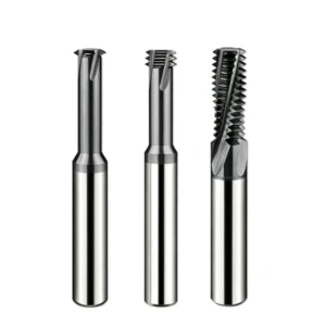
Practical Tool Selection Matrix for High-Hardness Mold Steels: From Quenched S136 to Powder Metallurgy Steels
Matching tools to hardened mold steels requires understanding microstructure rather than just Rockwell hardness numbers. We frequently see shops run into severe tool chipping because they apply pre-hardened steel parameters directly to fully hardened tool steels. Even at identical HRC60 ratings, electroslag remelted stainless steel behaves completely differently from high-carbon, high-chromium cold-work die steels.
Tool selection hinges on balancing impact toughness against resistance to thermal coating flaking. When thread milling S136 steel, high-chromium stainless retains a gummy, adhesive nature despite its hardness. Powder metallurgy steels like Vanadis or ASP, however, contain dense carbide phases that act like grinding wheels against tool flank faces. Using one generic cutter for both alloys causes rapid, uncontrolled tool failure.
Recommended Thread Cutter Tool Matches for Mirror-Finish Mold Steel S136 and SKD11
In medical mold shops across Europe and Asia, we run extensive trials on vacuum-hardened S136 at HRC58–60. The primary failure mode is localized heat buildup, which causes microscopic galling and tearing along thread flanks. To counter this, we configure the thread cutter tool with an open flute profile, high-lubricity coating, and polished flutes, generating clean, mirror-finished pitch diameters without tearing.
Hardened SKD11 and DC53 cold-work die steels demand the opposite approach. Coarse, undissolved carbides create extreme micro-brittleness that easily chips razor-sharp cutting edges. For these alloys, we use an ultra-fine carbide substrate with a reinforced negative hone along the cutting edge. This honed edge absorbs high-frequency shock loads without micro-fracturing under intense contact pressure.
Feed and Layered Milling Strategies for Metric vs. UN Thread Mills at HRC 65 Hardness
Field machinists often overlook how thread profiles alter cutting forces between thread standards. Metric 60-degree threads feature fixed root rads, while Unified (UN) and aerospace UNJ threads mandate precise root radii and flat crest truncations. These geometry differences change the tool tip’s instantaneous contact footprint in HRC65 material.
When programming a metric thread mill or UN cutter on extreme alloys, never cut to full depth in one pass. We standardise a three-pass radial strategy: rough out 70% of thread depth first, take a second pass of 0.05 mm to 0.08 mm to clean up deflection, and finish with a zero-depth spring pass. This procedure safeguards delicate tool crests and guarantees pitch diameter accuracy.
Pitfalls of Small-Diameter Blind Holes (M3–M6): Why We Strongly Discourage Multi-Tooth Full-Profile Tools on Ultra-Hard Materials
Machining dynamics change abruptly when hole diameters drop below M6. We often get emergency calls from shops breaking multi-tooth tools on M3 and M4 blind holes in finished mold blocks. Tight hole boundaries block chip flow entirely, while multi-tooth contact generates torsional forces that snap slender carbide necks in fractions of a second.
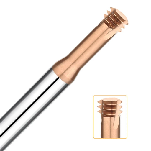
For sub-M6 holes in hardened alloys, we strongly advocate switching to a dedicated UN thread mill or single-point metric profile. Single-tooth milling cuts torsional load down to safe levels and leaves clear space for high-pressure air to flush abrasive dust out of the hole. Spending two extra minutes on multi-pass interpolation is far cheaper than scrapping a five-figure mold core.
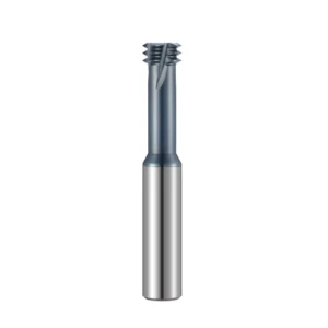
Cutting Parameters and Process Optimization: Achieving Stable Tolerances with HRC65 Thread Mills
Machinists often plug catalog surface speeds into ultra-hard jobs, only to break the cutter on entry. Past HRC60, parameters cannot be set in a vacuum. Spindle thermal growth, machine acceleration, and multi-pass strategies heavily influence edge life. Maximizing the tool life of a premium HRC65 thread mill requires balancing catastrophic chipping against thermal flank wear.
In our testing across European and American mold shops, cutting speeds must stay within a conservative window of 35 to 55 m/min. Rushing cycle times in this hardness zone is counterproductive. Instead, use controlled multi-pass strategies to relieve residual stress. Fine-tuning your feed and pathing to the CNC controller logic ensures repeatable thread pitch diameter tolerances that easily pass aerospace and medical standards.
Helical Interpolation and Multi-Pass Strategies: Comparing Ra Surface Roughness Between Single-Pass Machining and Multi-Pass Sidewall Finishing
Single-pass full-depth threading in ultra-hard alloys is a gamble you will eventually lose. We tested micro-surface finishes on powder metallurgy steel hardened to HRC64.8. Single-pass threading produced severe chatter, leaving flank roughness drifting between Ra 1.6 μm and 2.5 μm with visible micro-tearing. Switching to a three-pass routine—two roughing passes and one spring pass—consistently held surface finish under Ra 0.4 μm.
Multi-pass routing protects delicate cutting edges and allows the workpiece to recover from elastic deformation. We rough out 65% to 70% of theoretical thread depth first, use the second pass to clear the remaining profile, and leave a 0.02 mm to 0.03 mm skim cut. When comparing thread mill profile types, progressive cutting eliminates taper from tool deflection and prevents plug gauges from binding at the thread root.
Feed Rate Compensation and Spindle Coolant Testing for European and North American Machining Centers
Many catastrophic tool failures in Western shops happen because operators mix up tool centerline feed with peripheral cutting feed. On Heidenhain or Siemens controls, internal circular interpolation without adaptive feed compensation spikes tooth chip loads dramatically. A programmed feed of 0.02 mm/z can easily balloon to over 0.06 mm/z at the thread wall. In HRC65 stock, that instantaneous overload snaps carbide teeth instantly.
Coolant delivery is equally critical when setting up precision thread tools. We strongly advise against flooding cuts with standard water-soluble emulsion, as severe thermal shock causes micro-cracking along the cutting edges. High-pressure dry air at 0.6 MPa or minimum quantity lubrication (MQL) is far safer. A focused air stream flushes chips out of blind holes while eliminating thermal fatigue entirely.
Coating and Substrate Selection: Wear Performance of Ultra-fine Grain Carbide Matched with AlTiN/Si-based Nano-coatings in Dry Cutting
Base carbide substrate determines whether your tool can survive extreme radial cutting pressures. We grind our high-hardness cutters from sub-micron carbide rods with 0.2 to 0.4 μm grain sizes and transverse rupture strengths over 4200 MPa. Standard coarse-grain grades lack the shock resistance required for hard milling and fracture along grain boundaries under pulsating loads.
Coating chemistry dictates tool survivability in dry cutting. Silicon-rich AlTiN/Si nanocomposite coatings provide outstanding thermal shielding for any dedicated thread cutter tool. Above 800°C, the coating forms an amorphous silicon dioxide barrier measuring 3800 HV. This passive layer insulates the carbide substrate against heat transfer and slows flank wear during demanding cycles.
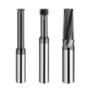
Cost Reduction and Technical Support – A Tool Manufacturer’s Guide to Balancing Unit Tool Costs Against Scrap Risk
Focusing strictly on cutting tool purchase prices is an expensive mistake. The real financial danger is scrapping a nearly completed, high-value component during the final threading pass. At HRC65, extreme cutting resistance, limited chip clearance, and brittle workpieces leave zero room for error. Real cost control means choosing a cutting strategy that eliminates part scrap entirely.
As an experienced thread mill manufacturer, we view tool selection as a calculated balance between cycle time and scrap probability. If you are machining thousands of shallow holes under 1.5D on rigid machines, single-pass cutters can save valuable seconds. However, if you are threading deep blind holes in five-figure mold inserts, partial-profile tools with multi-pass strategies provide the process security you need to safeguard margins.
Flexible Approaches for Prototyping and Small Batches: One Partial-Profile Tool Covering Multiple Pitches vs Dedicated Full-Profile Tools and Cost-Amortization Models
Carrying slow-moving inventory ties up critical shop capital. Standard full-profile cutters have a fixed pitch, meaning every thread specification demands its own dedicated tool. If part revisions arrive, those tools turn into dead inventory. Conversely, a partial-profile tool covers multiple thread pitches with the same flank angle, drastically cutting the number of carbide cutters you need to stock.
Your production volume should dictate tool selection. If you run low-volume prototypes or medical components, a partial profile thread mill keeps upfront tooling expenses low across diverse jobs. If you are running high-volume automotive contracts where seconds equal thousands of dollars, custom full-profile tools make sense. Keeping surface speeds conservative and runout near zero allows you to amortize tool cost across massive part volumes.
Field Technical Support Case Study: Troubleshooting “No-Go” Gauge Failures in German and North American Workshops
A “No-Go” gauge failing to stop is one of the most frustrating shop-floor issues, especially when the “Go” gauge enters smoothly. At a German mold maker, a “No-Go” gauge turned two full rotations into an HRC63 insert. The shop assumed the tool OD was cut oversize, but tool presetter checks proved tool dimensions were dead on. The real issue was programmed pathing.
Because the programmer omitted circumferential feed compensation, the cutter bogged down at quadrant transitions and deflected off-center. Paired with thermal checking from flood coolant, the tool distorted the thread root radius and created micro-burrs that allowed the gauge to enter. If you are running into gauge failures or tool chipping, verify your centerline feed output and air pressure. If you are facing tricky part drawings or tough alloys, let us review your application to dial in safe feeds and toolpaths.