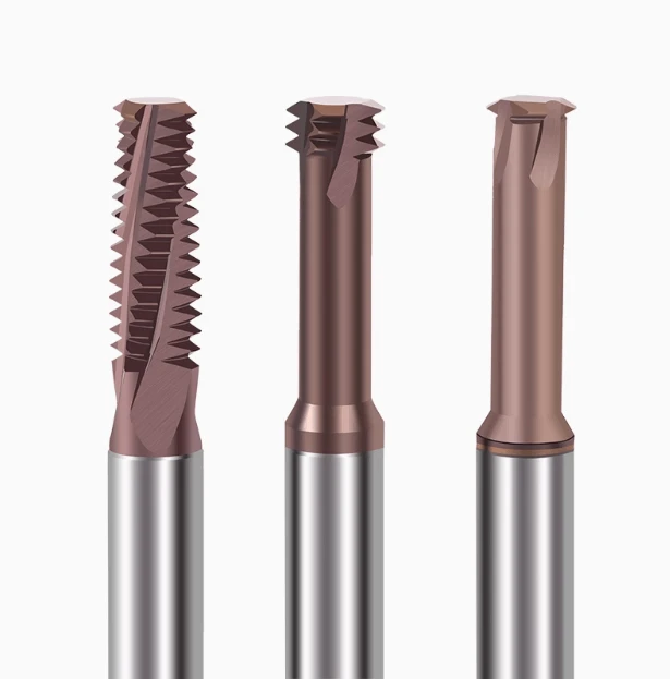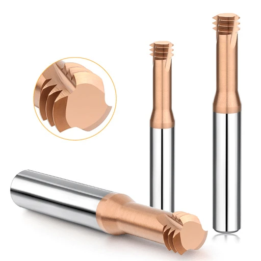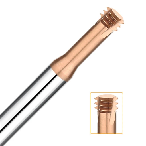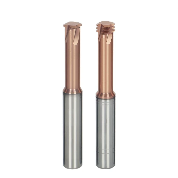
Two weeks ago, a German mold-and-die client emailed our technical desk photos of scrapped SKD11 stamping inserts. The job called for M4×0.7 blind-hole threads at a verified hardness of 64–65 HRC. The failure was immediate: the tool snapped inside the second hole. Its cutting edges showed severe shell-like micro-chipping, leaving carbide fragments buried inside a cavity worth thousands of dollars.
Their tooling manager called us right away: “Did your coating adhesion fail on this production lot? We followed your catalog speed to the letter—running right at 8,500 RPM. Why are we getting barely 20% of expected tool life?”
We have handled this exact complaint for over 16 years. When tackling medical bone plates in the US or hardened die steels in Europe, operators always blame the carbide substrate or the AlTiN/SiN coating first. But our shop-floor diagnostics never start with metallurgy. We pull the raw CNC program block and check the spindle’s dynamic load curves.
Most programmers treat hardened steel threads like standard profiling cuts. When dialing in HRC65 thread mill RPM, they rely on linear surface speed formulas (Vc = p*D*S / 1000). That calculation ignores the tight internal arc of cut inside a small bore, which radically spikes the effective chip load and radial kickback on the thread milling tool.
At 65 HRC, steel has near-zero plastic deformation. Even a 200 RPM mismatch sets off catastrophic thermal shock and fatigue at the tool tip. Run a thread milling cutter too fast, and the coating delaminates. Run it too slow out of caution, and the teeth rub and burn. Both mistakes ruin your carbide thread mill parameters.
As a dedicated thread mill manufacturer, we know speed is never an isolated dial setting on hardened D2, SKD11, or DC53. It is a balancing act between tool overhang, actual tooth contact arc, and machine harmonics. Does your VMC struggle with this balance, failing Go/No-Go plug gages even with high-end shrink-fit holders?

Why Thread Milling Hardened Steel Fails at the Spindle Speed Stage: A Shop-Floor Failure Analysis
When troubleshooting at client facilities, we routinely see operators tweak feed rate overrides while leaving the spindle speed dial untouched. Most machinists assume chipping in hardened steel comes from aggressive feeds. Under a stereomicroscope, however, failed crests usually show severe thermal spalling and edge erosion. At HRC 65, the workpiece cannot absorb shock through shear deformation; an off-target spindle speed spikes cutting pressure directly onto fragile teeth.
A textbook speed often ruins the cutter within its first helical entry. Hardened die steel is packed with dense, abrasive carbide phases. As the thread milling cutter travels along its toolpath, the teeth endure cyclic impacts across a razor-thin contact arc. If spindle speed drifts outside the stable zone, thermal equilibrium collapses. The carbide core then shatters under coupled mechanical and thermal fatigue.
Crossing the Critical Threshold: Micro-Chipping and Coating Delamination Caused by Excessive Speed
A customer running powder metallurgy dies at HRC 64–65 pushed spindle speeds to shave cycle seconds, snapping three M5 cutters in one morning. The failed tools showed minimal rake face wear, but the nano-composite coating near the cutting edge had flaked off like scorched paint. The bare tungsten carbide substrate then suffered instant intergranular chipping from high-frequency thermal shocks.
If a cutter sounds clean upon entry but snaps seconds later, your HRC65 thread milling speed has crossed the thermal redline. Pushing surface speed past the coating’s oxidation limit strips away its thermal barrier. The exposed sub-micron carbide core cannot survive high-speed rubbing against hard martensite. The sharp edge dulls into a compressive flat within revolutions, causing catastrophic shear failure.
Being Overly Conservative with Cutting Speed: The Adverse Effects of Frictional Heat Accumulation at Low RPMs
Backing off speed too far causes equally severe damage. We often review programs where engineers drop RPM to crawl through hard cuts, hoping to preserve tool life. In reality, cutting speed below the minimum chip threshold stops the tool from shearing chips cleanly. The cutting edge rubs hard against the hole wall, causing severe burnishing and instant work-hardening.
Chip evacuation is critical for heat transfer, as healthy chips carry away over 70% of cut-zone heat. Under low-speed rubbing, stagnant chips trap friction heat right at the cutter tip. When balancing your carbide thread mill parameters, remember that running too slow offers no safety margin. It accelerates abrasive flank wear, causes pitch taper, and cracks teeth through localized thermal stress.
Machine Spindle Rigidity and Runout Control: Real-World Speed Derating for BT40 vs. HSK63 Spindles
Before checking code, we inspect spindle taper condition and dynamic toolholder runout. On a BT40 taper running a collet chuck, standard gauge lengths easily push dynamic runout past 8 microns. With per-tooth chip loads of just a few microns, excessive runout means only one or two teeth take the entire cutting force. That imbalance triggers chatter spikes, ruining theoretical speed tables.
With rigid, dual-contact tooling like HSK63F or BIG-PLUS, superior damping and balance let you use the full thread mill RPM for hardened steel. If your spindle bearings are worn or tool overhang exceeds 3×D, drop catalog speeds by 15% to 20% to avoid harmonic chatter. Forcing high spindle speeds on a low-rigidity setup quickly snaps carbide teeth from micro-resonance.

Core Parameter Table: Reference Speeds and Feeds for Thread Milling Cutters Machining HRC 65 Hardened Steel
Machinists often ask us for a universal parameter cheat sheet. Frankly, after 16 years of tooling support, we know fixed numbers never work across every shop floor. Steel at HRC 65 approaches the brittle hardness of glass, with uneven tungsten carbides distributed throughout the matrix. Selecting operating numbers is a live balancing act between thermal flank wear and cutting edge toughness.
Our core field rule is strict: lock surface footage first, calculate center feed, and downscale for arc engagement. A premium thread milling cutter cuts 6H gauge threads reliably only within a narrow, safe cutting window. Pushing speeds to shave seconds spikes radial deflection and embeds fractured teeth into scrapped cavity blocks.
RPM for Small-Diameter (M3–M6) Thread Mills on Hardened Steel and High-Speed Spindle Balancing
M3 and M4 blind holes produce the highest tool mortality on micro-milling jobs. With tool diameters of 2.4 mm to 3.1 mm, slender necks lack torsional stiffness under heavy cutting loads. Programmers often run these micro tools past 20,000 RPM, only to break them within half a pitch. The culprit is rarely cutting torque, but dynamic imbalance creating high-frequency centrifugal chatter.
We run these tools in balanced HSK or shrink-fit holders at a conservative 55–75 m/min surface speed. When tuning your thread mill RPM for hardened steel, cap M3–M6 sizes between 7,000 and 9,500 RPM. Maintain dynamic balancing to at least G2.5, or G1.0 if possible. Eliminating centrifugal runout lets delicate teeth track smoothly through internal helical paths.
Cutting Speed Caps and Chip Clearance Margins for Medium-to-Large Thread Milling Tools (M8–M16)
At M8 and above, failure modes shift from tool deflection to torque spikes and trapped chip friction. Larger tool bodies carry stiffer cores, but their expanded contact arc generates severe localized heat against hard hole walls. Without capping surface speed, excessive frictional heat softens carbide edges and collapses tool geometry.
On shop floors, we cap surface speed for larger threads at 40–55 m/min. Large-diameter thread milling tool setups also require clear chip flutes and high-pressure dry air. Hardened steel chips fracture into gritty, abrasive dust. If poor air clearing traps these particles, teeth recut them against the wall, causing multi-tooth chipping.
Reference Table for Differentiated RPM Settings (HRC65 Thread Milling): External Threads vs. Blind-Hole Internal Threads
Treating external and internal thread parameters as identical is a costly mistake. External cuts follow a convex arc with minimal tooth wrap, letting chips fly free and heat escape easily. Internal cuts submerge teeth inside a concave cavity, multiplying engagement angle, trapped heat, and tool pressure.
Before cycling your machine, drop internal cutting speeds by 15% to 25% relative to OD milling. Never cut internal threads in a single pass at this hardness level; always split radial stock into multiple roughing and finishing passes. Match your target HRC65 thread milling RPM against the baseline reference values below:
| Thread Size | Tool Dia. (mm) | Operation | Cutting Speed Vc (m/min) | Spindle Speed (RPM) | Feed per Tooth fz (mm/z) | Pass Strategy |
| M3 × 0.5 | 2.35 | Internal Blind | 55 – 65 | 7,400 – 8,800 | 0.006 – 0.010 | 2–3 radial passes, full air blast |
| M4 × 0.7 | 3.1 | Internal Blind | 60 – 70 | 6,100 – 7,200 | 0.008 – 0.012 | 2 radial passes, high-pressure air |
| M6 × 1.0 | 4.6 | Internal Blind | 65 – 75 | 4,500 – 5,200 | 0.012 – 0.016 | Roughing pass + 0.03 mm finish pass |
| M8 × 1.25 | 6 | Internal Blind | 50 – 60 | 2,600 – 3,200 | 0.015 – 0.020 | 2 radial passes, gauge length < 3×D |
| M10 × 1.5 | 7.8 | Internal Blind | 45 – 55 | 1,800 – 2,200 | 0.018 – 0.024 | 3 radial passes to control crest heat |
| M12 × 1.75 | 9.5 | Internal Blind | 40 – 50 | 1,300 – 1,700 | 0.020 – 0.028 | 3 passes, direct dry air blast |
| M16 × 2.0 | 12 | Internal Blind | 38 – 48 | 1,000 – 1,300 | 0.025 – 0.032 | 3–4 passes, monitor low-end torque |
| M8–M16 OD | Various | External Thread | 55 – 65 | Scale up RPM by 15%–20% | 0.020 – 0.035 | Single or dual pass based on overhang |

Real-World Case Study: SKD11 Thread Milling (62–65 HRC) – A Solution for Hardened Die Steel
At an automotive progressive die plant, we troubleshot blanking die inserts made of high-carbon, high-chromium cold-work die steel. Quenched and tempered to HRC 63–65, deep M6 tapped holes caused severe issues. Dense martensite generated intense screeching after three holes. The pitch diameter measured tight on Go gauges, and thread walls showed noticeable taper error.
Shops often blame poor substrate toughness when tools fail in wear-resistant steels. Looking at the CNC logs, the real issue was underestimating the material’s yield strength. During SKD11 thread milling, high yield strength forces the cutting edge to shear metal at a narrow shear angle. Any lag between feed rate and spindle speed causes tool push-off. Fixing this requires matching steel metallurgy, toolholder rigidity, and CNC arc compensation.
SKD11 Mirror-Finish Mold Machining: Optimizing Cutting Speed and Feed Per Tooth for High-Hardness Carbide Segregation
Cryogenically treated mold steel with high surface finish requirements reveals micro-segregation quickly. SKD11 contains large undissolved primary chromium carbides (Cr7C3) exceeding HV 1800. Milling this steel feels like striking buried gravel at high speed. If surface speed runs too fast, the edge suffers thermal spalling; if feed is too light, teeth rub across hard carbide pockets.
We solved this by balancing edge strength and heat resistance: we locked cutting speed at 58–62 m/min and feed per tooth ($fz$) at 0.012–0.014 mm/t. We backed off spindle speed by a few hundred RPM to absorb carbide impacts, while keeping minimum chip thickness high. This chip load carries heat away from the cut, stopping localized heat buildup and stabilizing your HRC65 thread milling speed.
The Practical Impact of Tool Holder Selection on Dynamic Overhang (Hydraulic vs. Shrink-Fit Holders)
Toolholder stiffness is often overlooked on the shop floor. We ran identical deep-hole tests on a 5-axis BT40 machine comparing standard hydraulic chucks against short shrink-fit holders. Hydraulic holders dampen vibration well, but their bulky profile requires extra gauge length. Under alternating side loads in hardened steel, tool-tip runout reached 11 microns, chipping teeth on the loaded side.
Switching to a compact shrink-fit holder kept overhang under 2.8× tool diameter, cutting dynamic runout below 3 microns. Using a thread milling cutter in hard materials benefits from the 360-degree concentric clamping of shrink-fit tooling, which stops high-frequency deflection. Shrink-fit tooling offers less vibration damping than hydraulic chucks. If spindle speed enters a machine resonance zone, vibrations transfer directly to the carbide teeth, making conservative speeds the safer choice.
Helical Interpolation and Arc Compensation: Converting Linear Feed Rates to Actual Cutting Edge Velocity
Operators often calculate feed rate (F) from outer-diameter linear speed, only to watch the cutter chatter inside the bore. In standard G02/G03 helical interpolation, CNC controls track the tool centerline path, not the cutting edge against the bore wall. In small bores, the tool center follows a much tighter radius than the thread diameter, heavily increasing actual chip load at the cutting edge.
To prevent size errors and broken tools, apply centerline feed correction in your CNC program or CAM post-processor. Let $D$ be the nominal thread diameter and $d$ be the tool diameter. If Vf_edge is the linear peripheral feed rate, calculate the programmed center feed rate (Vf_center) using this ratio:
When setting carbide thread mill parameters, missing this step multiplies the actual load per tooth against the hole wall. This math error explains why parameters that work on linear cuts snap tools during helical thread milling.

Engineering Advice from Tool Manufacturers: Establishing a Closed-Loop Verification Process for HRC65 Thread Milling Parameters
After spending 16 years running shop-floor trials, our primary rule remains simple: never treat catalog data as law. In materials hardened to HRC 65, dial-in settings are not static inputs. You need a closed-loop verification process covering spindle dynamics, true surface speed, and heat control. Rushing setups without testing cuts often scraps multi-thousand-dollar mold cavities on hole one.
Tool failure traces back to unbalanced cutting mechanics: speed peeling coatings, slow feeds burnishing parts, or carbide inclusions in SKD11 shattering edges. Before finalizing your HRC65 thread milling parameters, run a three-hole validation loop. Check spindle load on hole one, verify gauge pitch diameter on hole two, and inspect edge wear under 50x magnification on hole three.
Perspectives from a Thread Mill Manufacturer: Balancing Carbide Substrate Toughness and Nanocomposite Coatings
As a specialized thread mill manufacturer, our internal design debates focus on balancing sub-micron grain size against cobalt volume, not just chasing peak hardness. Intermittent helical interpolation spikes cutting loads violently. If transverse rupture strength drops under 4,000 MPa, tips snap instantly. We pair 0.2–0.4 μm grain substrates with AlTiSiN coatings to handle 1,100°C friction heat.
If you struggle with broken tools in deep blind holes, recheck your carbide substrate choice. Fragile substrates cause brittle edge fracture, while low red-hardness causes plastic tool failure. When facing long overhangs or minor machine chatter, pick a tougher substrate with a micro-honed cutting edge. A honed edge delivers much wider operating safety than brittle, razor-sharp teeth.
Multi-pass Strategy and Spindle Speed Coordination: Dynamic Speed Adjustment for Rough Milling and Thread-Root Finishing
Single-pass thread milling at HRC 65 is guaranteed tool suicide. When troubleshooting gauge binding or pitch taper from tool deflection, we stage cut depths to lower radial force. Roughing cuts remove 90% of material volume under high lateral shock. Finishing passes shave off just a few hundredths of a millimeter, where rubbing quickly generates extreme surface heat.
If you see torn root finishes or pitch taper, decouple roughing and finishing speeds. Drop surface speed 8% to 10% during rough passes across 2 to 3 steps to tame shock loads. For the final spring pass, return to baseline hrc65 thread milling RPM and cut feed per tooth in half. This speed shift cleans up tooth flanks without deflection.
The Critical Cooling Strategy: Lessons on Thermal Shock and the Case for Air Cooling in Hardened Steel Thread Milling
Using liquid coolant on hardened tool steel creates massive shock problems. We regularly stop shop operators from turning on flood coolant or high-pressure water. In HRC 65 cuts, teeth spike past 800°C during engagement, then quench instantly in coolant fluid. This violent thermal cycle sparks spiderweb cracks across the carbide edge, shattering teeth within seconds.
When threading SKD11 or D2, shut off flood coolant and switch to clean, high-pressure dry air or MQL. High-pressure air blasts hot, abrasive dust out of the bore to stop chip recutting. Every setup, fixture, and heat-treat batch differs; if you face tight limits on specific part prints, we can review your hrc65 thread milling parameters and cycle paths directly.