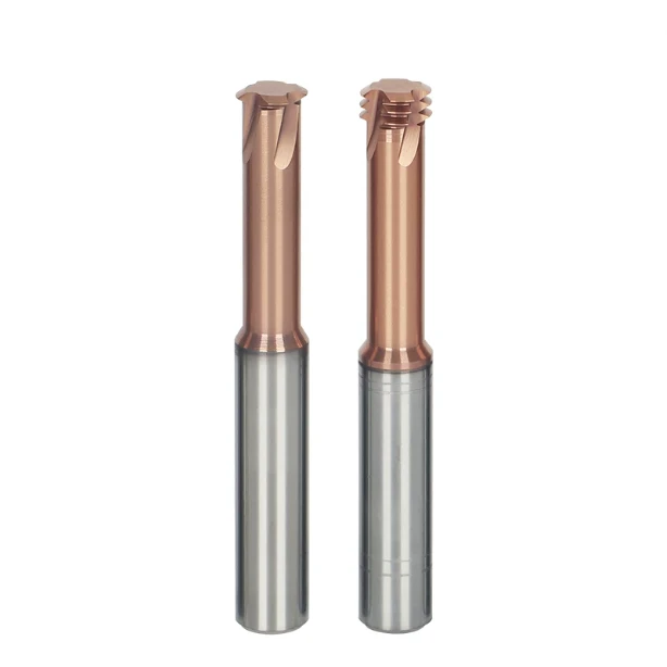
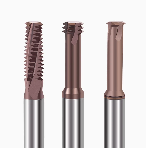
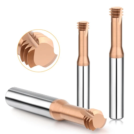
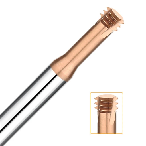
Last month, we assisted a German automotive mold shop running a batch of SKD11 stamping inserts hardened to HRC 62–64. The operator drilled the pilot hole and loaded a brand-new solid carbide tool for an M6×1.0 internal thread. Halfway through the first helical interpolation pass, a sharp snap echoed across the shop floor. The tool had sheared off flush inside the hole.
This is not an isolated incident. In our 16 years of supporting machine shops across Europe and North America, we see this breakdown every few weeks. Programmers enter textbook feeds and speeds into their CAM software, but once workpiece hardness tops HRC 60, the tool tips chip, threads gauge out tapered, or the cutter snaps entirely.
The problem is rarely tool rigidity. Most programmers setting an HRC65 thread mill feed rate forget to compensate for the actual tool-center path during internal helical moves. A minor calculation error that standard pre-hardened steel forgives will instantly destroy a cutter when cutting hardened die steel above 2200 MPa tensile strength.
If a high-performance cutter cannot survive three holes on your CNC mill, should you really blame the coating? Or did the programmed thread milling feed and speed overload the tooth profile before the tool ever touched the cut?
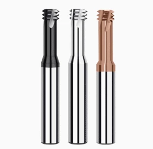
Defining the Operating Conditions for Hardened Steel: Why Do General-Purpose Cutting Parameters Inevitably Cause Edge Chipping?
Many machine shops treat hardened steel like typical pre-hardened material: cut the RPM in half, dial back the feed, and hit cycle start. In our experience, this linear reduction is a death sentence for the cutting edge. Machining materials past HRC 60 is not just about faster abrasive wear. The physics of plastic deformation changes completely. The cutting edge faces sudden brittle fracture instead of steady shearing.
We frequently stop operators from using catalog charts on hardened stock. Those tables assume ductile chips that curl and evacuate cleanly. With hardened die steels, slight feed errors push your chip thickness into severe burnishing or outright shear overload. Dialing in the proper thread mill feed rate for hardened steel requires understanding the microscopic shock loading that happens every time a tooth engages the hole wall.
From Cutting Heat to Tool Deflection: Fundamental Differences in Cutting Force Feedback Between HRC 60–65 Workpieces and Conventional Quenched-and-Tempered Steels
In medium-carbon steels like 4140, chip shear carries away substantial cutting heat. With cryogenic SKD11, D2, or DC53, the material resists plastic flow and creates powdery, fragmented chips. Over 80% of cutting heat concentrates within a shear zone only microns wide. Because fragmented chips cannot carry this heat away, thermal energy dumps straight back into the cutter tooth.
Radial cutting forces surge simultaneously, causing severe tool push-off. With standard steels, deflection causes minor size errors; with hardened alloys, it destroys the tool. Operators often see an undersized pitch diameter and mistakenly increase radial wear offsets, which triggers chatter and snaps the neck. An excessively light feed promotes rubbing, while an aggressive feed shatters the tip. The safe window for your thread milling feed rate is remarkably narrow.
Tool Selection Criteria: Rigidity-to-Overhang Ratio, Ultrafine-Grain Substrate, and Heat-Resistant Coating Requirements for Carbide Thread Mills in High-Hardness Applications
Tool overhang is where outsourced shops pay the steepest price. We always measure stickout with calipers before touching cutting data. Increasing your length-to-diameter ratio from 2.5D to 3.5D triples tool deflection under radial load. For hardened deep-hole applications, we strictly select neck-relieved carbide thread mills with reinforced core shanks to counteract side loads during circular interpolation.
Substrate and coating selection demand equal discipline. We specify sub-micron carbide substrates (0.2–0.4 µm) that preserve edge sharpness without sacrificing transverse rupture strength. General-purpose TiAlN coatings degrade rapidly under these thermal spikes. We rely on nanocomposite AlTiSiN coatings rated for 1100°C. They generate an aluminum oxide layer that stops cobalt leaching during dry or MQL cutting.
Tool Wear Mechanisms: Micro-chipping and Severe Flank Friction During Micro-chip Formation in Hardened Steel Threading
Inspecting worn cutters under a microscope reveals the exact failure mode. Standard steel tooling typically fails via flank wear or cratering. A threading cutting tool running in hardened steel fails primarily through micro-chipping at the crest radii. Hard carbide precipitates embedded in the steel strike the cutting edge like thousands of micro-hammers per minute.
If your chip load is too light, the edge rubs rather than cuts. Compressive stress fractures the delicate crest geometry. Once micro-chipping begins, cutting forces spike, flank friction builds rapidly, and the heat can generate a work-hardened white layer on your thread flanks. Never run an excessively light feed to “protect” the cutter; keeping a stable, minimum chip load yields far longer tool life than timid cutting.
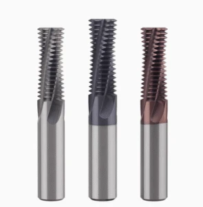
Core Algorithms and Corrections: The True Method for Calculating Thread Milling Feed Rates in Machine Programming
We frequently encounter a frustrating issue during shop floor troubleshooting. Machinists set cutting speeds and tooth loads flawlessly in CAM software, yet the tool tip shatters the instant circular interpolation begins. This failure rarely stems from inconsistent core hardness. Instead, it comes from confusing the programmed machine feed rate with the actual cutting speed at the tool edge. In linear milling, both values align; in small-hole internal interpolation, path distortion causes severe edge overload.
To stop catastrophic failure in hardened materials, you must calculate the tool center path and outer edge geometry separately. CNC controls regulate the tool center trajectory by default, not the peripheral contact point. Without mathematically scaling this value down, your programmed feed gets multiplied at the cutting edge. Applying a mathematically corrected thread milling feed rate ensures your tool stays well within its mechanical fracture limit.
Differences Between Linear Cutting and Internal Threading Circular Paths: Why Directly Applying External Milling Feed Rates Leads to Overload and Chipping at the Thread Crest
In linear milling, if the tool center travels 100 mm, the peripheral cutting edge also moves 100 mm, maintaining a stable chip thickness. In internal thread milling, the tool center rotates along a tiny radius while the edge sweeps the larger hole circumference. This creates a severe physical discrepancy. The arc length covered by the outer edge is much larger than the center path, compressing material removal into a very narrow engagement zone.
Many programmers mistakenly apply linear or external milling tooth loads directly to internal hole cycles. This oversight increases the instantaneous crest chip thickness by 1.5 to 2.5 times. In standard carbon steel, that spike merely causes surface roughness or load meter jumps. In hardened steel, sub-micron carbide cannot absorb that tangential impact. Before a normal shear zone forms, the crest tip suffers instant, pulverizing edge failure.
Machine Center Feed Correction Formula: Calculating Parameters Based on Tool Diameter and Nominal Thread Diameter for the Actual Thread Milling Feed
To keep the tool edge cutting at your intended chip load, you must convert the peripheral feed to a center feed. Our shop-proven formula uses a straightforward geometric reduction factor: Fm = Fe · (D – d) / D. Here, Fm represents the tool center feed, Fe is the linear edge feed, D is the nominal major thread diameter, and $d$ is the tool cutting diameter.
Take an M8×1.25 thread in hardened tool steel using a 6.0 mm cutter. If handbook data recommends an edge feed (Fe) of 120 mm/min, putting 120 mm/min directly into a G02/G03 block forces the edge to slam into the wall at nearly 480 mm/min. Applying the formula reduces the programmed center feed to 30 mm/min. This adjustment establishes a safe thread mill cutting feed within the machine coordinate system.
Common Errors by Western Clients: Troubleshooting and Correcting Conflicts Between CAM-Output Linear Feed and CNC System Arc Feed Compensation
When auditing shops across North America and Europe, we find that nearly half of all breakages stem from double-compensation errors. Modern CAM packages include internal arc feed deceleration options. Programmers often output an already reduced centerline feed from CAM, while the machine operator simultaneously runs internal CNC radius compensation on Fanuc, Heidenhain, or Siemens controls.
Compounding these reductions slows the tool into a crawl where the edge merely burnishes hardened stock, overheating the cutter within seconds. Conversely, outputting linear edge feed without machine compensation instantly overloads the tool tip. We recommend picking one clear standard: either lock centerline output in your CAM post-processor or standardize edge feeds with machine macros. Never leave compensation rules open to interpretation.

The Impact of Flute Count on Feed Rates: Choosing Between 3-Flute and 4-Flute Thread Milling
Many machinists assume higher flute counts automatically deliver faster cycle times. On the floor, operators frequently swap a 3-flute cutter for a 4-flute thread milling tool and push the table feed by 33%. The tool often turns blue and fails on hole one from poor chip evacuation and heat buildup. Hardened steels above HRC 60 are unforgiving regarding chip space; changing flutes alters your tool’s entire cutting dynamic.
Choosing between flute counts requires balancing chip evacuation space against shank rigidity. Adding a flute compresses gullet clearance while providing a thicker, stiffer core. If you push feed rates without checking your depth-to-diameter ratio, the machining sound changes from a clean cut to abrasive rubbing. Balancing these factors determines how you program 3 flute vs 4 flute thread milling feeds for predictable tool life.
The Trade-off Between Rigidity and Chip Clearance: 3-Flute Evacuation Advantages vs. 4-Flute Core Rigidity in Deep, Hard-Material Threading
For blind holes deeper than 2.5D, we consistently recommend a 3-flute design. At HRC 60–65, chips are powdery and fragmented. Even with high-pressure blast or micro-lubrication, shallow flutes pack these fine chips together, causing destructive secondary cutting at the bottom of the hole. A 3-flute geometry offers wider channels, allowing pressurized air to clear debris before the next tooth sweeps through.
A 4-flute cutter excels at depths around 1.5D or in shallow through-holes where deflection is your main concern. The additional flute increases the core cross-sectional area by roughly 20% to 30%, adding bending stiffness against high radial forces. While this rigidity limits elastic deflection at the shank, packed chips in tight spaces cause rapid chipping. Evaluate hole depth carefully before making your choice.
Resetting Feed per Tooth (fz): Avoiding Excessive Tooth Load When Increasing Feed Rate with 4-Flute Tools
A frequent mistake when moving to 4-flute cutters is keeping the same feed per tooth (fz). Machinists often keep fz steady and expect the fourth tooth to deliver free cycle time gains. However, cutting hardened steel creates cumulative radial force within the engaged arc. Because 4-flute tools have overlapping tooth engagement, unadjusted feeds overload the sharp corner radii.
Our standard rule is to lower baseline chip thickness by 15% to 20% when moving from 3 to 4 flutes before calculating table feed. This protects cutting edges from instantaneous force spikes that exceed carbide toughness limits. Moderately shortening cycle times while protecting your teeth is the safest path to balanced thread milling feed and speed parameters.
Chatter Suppression in Practice: Performance Comparison of 3-Flute vs 4-Flute Thread Milling Feeds in Long-Overhang Applications
We captured distinct vibration data while solving a long-overhang challenge for a medical mold shop. Due to fixture walls, tool overhang exceeded 4D. Running a 4-flute cutter produced an intense high-frequency squeal, even after dropping surface footage by half. The resulting thread flanks showed white chatter bands, and the Go gage seized halfway down.
We resolved the issue by switching to an unequal-pitch 3-flute tool and revising the 3 flute vs 4 flute thread milling feeds strategy. The wider, uneven tooth spacing broke the resonance harmonics of each impact. Spindle vibration dropped immediately, and surface finishes cleared up to accept the gage. Reverting to three flutes provides a cleaner entry and often resolves stubborn chatter in long-reach setups.

On-site Measured Parameter Table for Mold Steels: Thread Mill Feed Rates for SKD11 (HRC 60–63) and HRC 65 Mold Steels
When mold steel hardness climbs into the HRC 60–65 range, theoretical numbers must pass the test of machine dynamic rigidity. While supporting stamping and die-casting shops, we constantly deal with high-carbon, high-chromium cold-work steels treated with cryogenic quenches. These alloys pack a high density of primary carbide precipitates. Every pass subjects the cutting edge to continuous, high-frequency impacts.
The benchmarks below come from hundreds of actual breakage and wear trials on Makino, Hermle, and Haas machines across Western customer sites. Factors like spindle balance, shrink-fit clamping, and tool stickout will always require fine-tuning on the floor. Even so, using these values as a verified starting point for your thread mill feed rate for SKD11 will keep you from destroying cutters during initial setup.
Cutting Benchmarks for Typical Sizes: Recommended Parameter Matrix for Thread Milling Feed and Speed (Vc, fz, and Fm Adjusted for Machine Compensation)
Setting your cutting speed (Vc) requires strict restraint. Hardened materials are hypersensitive to frictional heat. Running at 60–80 m/min triggers thermal fatigue cracks in the coating within seconds. We keep Vc between 35–45 m/min for HRC 60–63 stock. When dealing with extreme HRC 64–65 inserts, drop Vc down to 25–32 m/min to maintain edge integrity.
The following field-tested parameters apply to 4-flute solid carbide cutters, listing the exact machine-compensated center feed (Fm):
| Thread Size | Hardness | Tool Dia (d) | Vc (m/min) | Spindle (RPM) | Edge fz (mm/z) |
Center Fm (mm/min)
|
| M6×1.0 | HRC 60–63 | ϕ4.5 mm | 38 | 2680 | 0.012 | 32.2 |
| M6×1.0 | HRC 65 | ϕ4.5 mm | 28 | 1980 | 0.008 | 15.8 |
| M8×1.25 | HRC 60–63 | ϕ6.0 mm | 40 | 2120 | 0.015 | 31.8 |
| M8×1.25 | HRC 65 | ϕ6.0 mm | 30 | 1590 | 0.01 | 15.9 |
| M10×1.5 | HRC 60–63 | ϕ7.5 mm | 42 | 1780 | 0.018 | 32 |
| M10×1.5 | HRC 65 | ϕ7.5 mm | 32 | 1360 | 0.012 | 16.3 |
After applying the (D – d) / D correction, the controller feed often drops to 15–35 mm/min. This slow, rigid micro-shearing is normal for a dialed-in thread milling feed and speed setup; never override it because it looks slow.
H3: Radial Layered Cutting Strategy: Radial Step-Cutting Allocation (ae) for Hardened SKD11
Cutting a thread in a single helical pass works fine on mild steel. On hardened steel, full profile engagement spikes radial extrusion forces, causing instant deflection or catastrophic shank fracture. For anything above HRC 60, split the full thread depth into two or three radial passes. Do not split passes evenly; scale them down to match diminishing cutting loads.
We rely on a 3-pass “Rough–Semi-finish–Spring” sequence. The first pass removes 60% to 65% of the total thread depth in stable material. The second pass takes 25% to 30%, correcting taper caused by initial tool deflection. The final pass removes just 8% to 10% (ae ≤ 0.04 mm) to clean up the profile, eliminating thread taper and preventing tight gage fit.
Cooling and Chip Evacuation Media: A Comparative Study of MQL vs High-Pressure Cold Air in Extending Thread Milling Tool Life
Coolant choice causes widespread confusion in hardened thread milling. Many shops flood the hole with water-soluble coolant, thinking it dissipates heat. In small blind holes, liquid coolant cannot coat the shearing interface evenly. The intermittent cutting causes rapid thermal shock between hot engagement and cold coolant, inducing micro-cracks that snap teeth within two holes.
Our tests on hardened tool steels prove that dry cold air and Minimum Quantity Lubrication (MQL) win on tool life. For HRC 60–63 stock, plant-based MQL provides an extreme-pressure film that stops flank adhesion. At HRC 65, filtered cold air at 6 bar and -5°C is far safer. Its kinetic force blows fragmented chips clear, preventing recutting and protecting your thread milling tool profile.
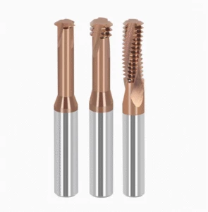
On-Site Setup and Troubleshooting: A Checklist to Avoid Pitfalls When Optimizing Feed Rates for HRC65 Thread Milling
When moving from program simulation to test cuts, theoretical formulas face the harsh reality of gage fit and CMM inspection. We frequently see machinists struggle when good cutters scrap expensive parts with tapered or distorted threads. High-hardness materials amplify the smallest mechanical flaws, turning setup into a disciplined error-correction routine.
Do not guess by blindly spinning feed dials or buying expensive holders. Instead, read your chip dust, listen to the cutting pitch, and feel the resistance on your thread gages. Nailing a reliable hrc65 thread mill feed rate requires syncing the tool-center feed with actual deflection, machine acceleration, and lead-in paths. If your threads fail inspection, follow this verified troubleshooting sequence.
Compensating for Tapered Threads (Larger at the Bottom, Smaller at the Top): Adjusting Feed and Tool Paths to Eliminate Deflection in Long-Overhang Tools
If you are threading blind holes deeper than 2D and the Go gage binds halfway down, tool deflection is your primary suspect. At HRC 65, radial cutting forces push the cutter away from the cut. Because the tool shank flexes most at the hole bottom, the thread pitch diameter cuts undersized near the floor, leaving a reverse taper.
Opening up your overall tool offset will only make the entry loose and fail the No-Go gage. If you are struggling with thread taper, you can switch to a stepped, radial rough-and-finish pass structure. Keep your final spring pass extremely light (ae ≤ 0.03 mm); if your controller supports taper interpolation, add a minor angular taper compensation to cancel out physical tool deflection.
Troubleshooting Thread Gauge Failures: Distinguishing Between Insufficient Wear Allowance and Thread Profile Deformation Caused by Low-Feed Stick-Slip
If you keep adjusting radial offsets but the gage binds—or suddenly passes both Go and No-Go checks—stop inspecting the tool and check your feed axes. Machinists often turn feed overrides way down out of caution, dropping center feeds below 10 mm/min. At this crawl, servo axes suffer stick-slip; the tool rubs instead of shearing, crushing the 60° profile angle.
Separate normal wear from machine lag: if the Go gage gets tight after several parts and the tool shows a smooth flank wear band, offset for normal tool wear. If a brand-new tool fails the gage immediately on part one, you can recalculate and raise your thread mill feed rate. Moving the chip load above the burnishing threshold restores clean shearing and stabilizes axis motion.
Optimizing Entry and Exit Paths: Eliminating Tool Marks with 180° Tangential Arc Lead-in/Lead-out
If optical inspection shows a notch, flat spot, or witness mark at the start of the thread helix, inspect your CAM lead-in moves. Direct 90° radial plunges cause cutting pressure to spike instantly against hardened steel. This shock load leaves gouge marks on the wall and fractures delicate tooth tips upon entry.
The cleanest fix is using a 180° tangential arc lead-in and lead-out paired with your corrected feed rate. This allows the cutter to ramp into full depth along a smooth helical sweep. After completing the full 360° circle, extend the path with a 90° to 180° overlapping tangential exit. This motion eliminates shock spikes, leaving a seamless, gage-ready surface finish on hardened alloys.
Every setup has its own quirks depending on machine rigidity, holder style, and heat-treat consistency. If you are struggling to dial in parameters for cold-work die steels (SKD11, D2, or DC53) or tricky long-overhang jobs, we can look over your part prints, machine setup, and hole data together to build an optimized cutting strategy.