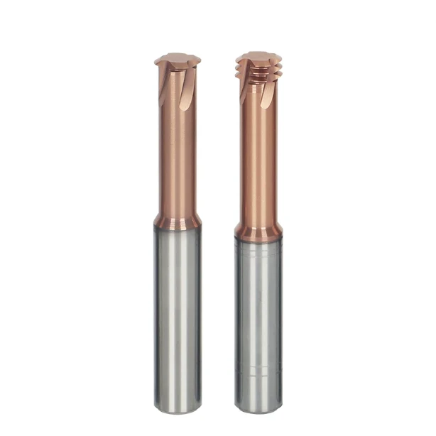
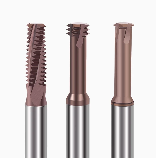
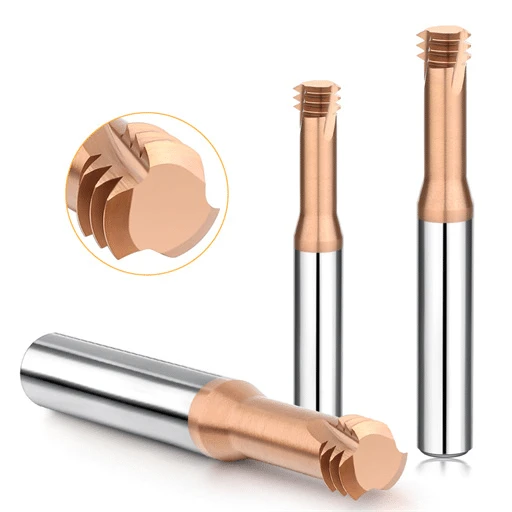
Two months ago, a machine shop supervisor at a German mold plant sent us a late-night video. They were running two stamping dies made of SKD11/D2 tool steel, vacuum-hardened and double-tempered to HRC65. During M8×1.25 helical interpolation, their solid carbide cutter snapped before finishing the first pitch. The broken tool body was wedged inside a five-figure workpiece.
In our sixteen years of engineering cutting tools for US and European shops, we see this exact first-pass failure every month. Seasoned machinists handle 40–50 HRC steels every day, but past HRC60, traditional habits fail. The fastest way to snap a cutter is blindly pulling linear parameters from a catalog or running standard thread mill feed per tooth values without internal arc compensation.
At extreme hardness, tool deflection and micro-edge toughness reach their breaking points. Programming an unadjusted 0.015 mm/tooth ignores the huge velocity gap between the tool center path and the outer cutting edge. The actual cutting force spikes, shattering the tool. Surviving this hardness requires custom math, specific micro-geometries on a solid carbide thread mill for hardened steel, and CNC path adjustments.
Does the feed rate on your machine screen match what your cutting edge actually feels against that hard matrix?
Why Does the Standard Thread Mill Feed Per Tooth Calculation Cause Tool Breakage in HRC65 Hardened Steel?
At HRC65, metal no longer yields through plastic shear deformation to create clean, curling chips. Instead, cutting becomes a high-pressure cycle of micro-extrusion, crushing, and brittle fracture. Traditional linear feed formulas assume straight-line toolpaths or external contours. They completely fail to account for the geometry of internal hole interpolation.
We routinely watch programmers dial in standard thread mill feed per tooth numbers, only to snap flutes on the first lead-in. It is rarely a lack of machine rigidity or poor carbide grades. Standard textbook formulas hide the non-linear chip thickness spikes caused by small internal diameters. At HRC65, carbide has zero cushion for error. A 20% spike in edge load causes catastrophic chipping within milliseconds.
The Effective Feed Trap in Internal Circular Interpolation: Why Actual Edge Load Dwarfs Controller Readouts
Your CNC screen shows the feed rate of the tool center point (TCP), not the outer cutting teeth. When cutting an internal thread, the cutting edge travels along the larger part diameter, while the tool axis moves along a much tighter inner circle. Because the tool center covers less ground per revolution, the outer cutting edge moves far faster than programmed.
Without calculating an arc-reduction factor, the controller forces the cutting edge to engage the metal at an aggressive, unmanaged pace. In mild steel, that extra chip load causes surface chatter; in HRC65 tool steel, the instantaneous compressive stress crushes the coating and base carbide. Whenever we troubleshoot broken tools for clients, our first step is calculating the thread milling cutting feed at the tool center. That adjustment alone resolves most breakage.
How an Oversized Thread Mill Diameter Relative to Bore Size Triggers Edge Chipping
Machinists often pick the thickest cutter that fits the hole to maximize tool-body rigidity. In hardened steel, this strategy backfires. We once troubleshot an M6 tapping job in hardened D2 where the customer chose a 4.8 mm cutter. When the thread mill diameter exceeds 75–80% of the minor diameter, the arc of contact wraps tightly around the bore wall.
This large contact arc traps the cutting tooth in the cut for too long during every revolution. Micro-chips have no space to clear and grind between the flute and the fresh thread profile. Long engagement also blocks cold air or mist from cooling the cutting zone. Our shop data proves that large contact arcs cause immediate transverse chipping rather than steady flank wear. A smaller cutter creates more clearance and extends life.
Real-World Failure Data: Chip Evacuation Failure and Built-Up Edge (BUE) in 60–65 HRC Mold Steels
Analyzing broken tools returned from production lines showed us that over 60% of failures do not stem from raw cutting resistance. They happen because powdery micro-chips weld together inside the hole. Hardened steel chips are fine, hot, and abrasive. If high-pressure air does not clear them within half a pitch, they pack into the flutes and trigger Built-Up Edge (BUE).
Under HRC65 loads, BUE does not protect the tool; it tears away the polished rake face. As chips cold-weld to the carbide, the rake angle turns negative, spikes cutting resistance, and shears off the tooth. When executing thread milling SKD11 HRC60–65 inserts, we limit the axial depth per pass and blast dry, cold air directly into the bore. Keeping the flutes clean matters more than pushing cycle times.
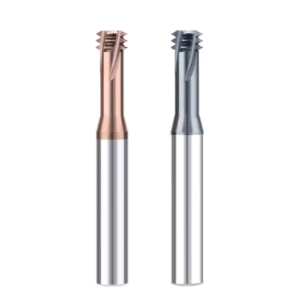
Establishing Practical Calculation Rules and Operational Adjustments for HRC65 Thread Milling Parameters
At HRC65, standard tool catalog charts are rough starting points, never definitive rules for the shop floor. Over sixteen years of optimizing five-axis setups across the US and Europe, we have learned that hard milling is not about material removal rates. It is about locking in a narrow, safe operating window between fracture toughness and cutting heat. At this extreme hardness, the steel matrix cannot yield plastically, turning even minor feed spikes into chipped flutes.
Setting reliable HRC65 thread milling cutting parameters requires calculating real-world machine constraints rather than memorizing speed tables. We adjust our programs based on pre-drilled hole straightness, tool overhang, and the chip evacuation medium. A balanced setup prioritizes edge survival over raw speed. Adding twenty seconds to a cycle is always cheaper than EDM-burning a broken carbide shank out of a finished die.
Two Empirical Formulas for Adjusting Thread Mill Feed Per Tooth Based on Thread Pitch
Fine and coarse threads distribute cutting forces in fundamentally different ways. For fine pitches (P ≤ 1.0 mm), the contact width is small, but under-feeding causes the tool to rub and work-harden the cut. For coarse pitches (P ≥ 1.5 mm), the tooth contact area spikes dramatically. This surge creates heavy torsional shear across the tool neck, causing standard rules of thumb to fail immediately.
To find safe parameters on the shop floor, we use two pitch-dependent formulas to dial in the actual thread mill feed per tooth. On fine threads, we set the minimum chip thickness as our floor to stop the cutting edge from burnishing hardened stock. On coarse threads, we apply a pitch-reduction penalty factor to scale back the chip load per tooth. This differentiated calculation method consistently prevents sudden transverse tooth fracture.
CNC Conversion of Thread Milling Feed: From Theoretical Linear Feed to Actual Arc-Compensated Feed
Machinists often overlook the geometric gap between the tool center path and the outer cutting edge during internal arc moves. If you program an external linear feed rate directly, the CNC controller applies that speed to the tool center. Because the outer teeth travel along a much larger radius, they hit the material significantly faster than programmed. In HRC65 steel, this instantaneous overload snaps carbide teeth instantly.
We require programmers to calculate the center feed rate reduction within their post-processor or macro program. You must multiply the tip feed by the difference between the thread major diameter and the tool diameter, then divide by the major diameter. This calculated thread milling cutting feed may look unusually slow on your digital readout. However, keeping the tool tip within its true chip-load limit is the only way to survive internal helical milling.
Dynamic Balance Between Cutting Speed (Vc) and Feed per Tooth (fz): Preventing Premature Mechanical Fatigue
Cutting speed and feed per tooth cannot be adjusted independently in hard milling. Higher surface footage generates severe frictional heat within a narrow shear zone. High feed rates, on the other hand, multiply cyclic impact forces. Failed tools examined in our lab show that thermal stress from excessive speed frequently combines with mechanical overload from aggressive feeds to destroy the cutting edge.
In 65 HRC steel, we run moderate-to-low surface speeds to preserve thermal stability, combined with light, positive feeds to avoid rubbing. Overheating the cut softens the carbide substrate beneath its nano-coating, causing micro-spalling. Dropping the feed too low simply polishes the hardened layer and accelerates flank wear. Balancing cutting speed with controlled thread milling hardened steel parameters stops premature edge fatigue before it starts.
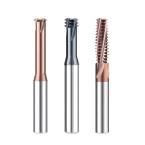
Conquering Hardened Mold Steel: Rigidity and Toolpath Strategies for Solid Carbide Thread Mills
Milling vacuum-hardened, high-carbon mold steel generates reactive cutting forces on a completely different scale than soft machining. Even with a rigid 50-taper spindle, the slender thread milling body remains the most flexible link in the setup. We always remind shop managers that winning in hard milling is less about buying the most expensive machine and more about planning a toolpath that mitigates tool deflection.
When running a dedicated solid carbide thread mill for hardened steel, you cannot rely solely on the transverse rupture strength of the carbide. You must design cutting paths that actively minimize radial push-off forces. A sudden spike in lateral load triggers micro-chatter, which strips the PVD coating in fractions of a second. Success demands combining multi-pass radial stepovers, smooth lead-in arcs, and rigid toolholder assemblies into a unified process.
Practical Guidelines for Radial Passes When Thread Milling SKD11 (HRC 60–65) Mold Inserts
Trying to cut full thread depth in a single pass on hardened cold-work tool steel guarantees a broken cutter. When helping a stamping facility optimize thread milling SKD11 HRC60–65 inserts, our first move was enforcing a radial multi-pass strategy. Under high cutting resistance, radial pressure spikes exponentially during full-profile engagement. A single pass simply cannot prevent the cutter from deflecting axially and radially.
We recommend a decreasing-depth stepover: take 50% to 60% of the thread profile on the first pass, 30% on the second, and save a light finish pass for the rest. This approach balances the cutting force across passes, preventing edge overload near the root. Taking multiple passes adds roughly ten to fifteen seconds per hole. That small time investment completely eliminates tool breakage and costly spark-erosion rework.
Climb Milling vs. Conventional Milling: Toolpaths to Eliminate Deflection and Spring-back Vibration
While climb milling is the standard for CNC machining, internal helical interpolation requires careful force vector control. In general thread mill CNC programming, climb milling from the bottom up allows the tooth to enter at maximum chip thickness and exit cleanly at zero thickness. However, in deep, hardened holes, the initial bite can flex the cutter toward the center, causing it to spring back and chatter violently.
To eliminate this deflection chatter, we maintain climb milling but use a helical roll-in entry arc spanning 90° to 180°. Never plunge or plunge-ramp the cutter straight into the hole wall along a linear vector. A smooth tangent entry introduces chip load gradually, eliminating shock. Exiting along a matching roll-out arc prevents stress concentrations and leaves a smooth, step-free thread pitch diameter.
Critical Impact of Overhang Ratio and Tool Holding on Thread Mill Rigidity
Tool overhang is the most unforgiving variable in hard machining. Deflection increases with the cube of the overhang length, while resistance scales with the fourth power of the shank diameter. When a deep-hole setup forces you to use an extended length with a compact thread mill diameter, keeping the length-to-diameter (L/D) ratio below 3:1 is critical. Beyond that limit, even twenty microns of deflection will visibly distort your thread flank angles.
We still see production shops using standard ER collet chucks for high-hardness thread milling, which is a common root cause of premature failure. Standard spring collets lack the clamping rigidity and runout control needed for 65 HRC work. We mandate hydraulic chucks or precision shrink-fit holders to keep total radial runout under 0.003 mm (0.0001″). Minimizing overhang down to the exact thread depth is your best defense against catastrophic failure.
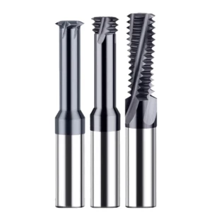
Extending Thread Milling Tool Life: Troubleshooting Common Machining Defects in Hardened Steel
Evaluating tool performance in 65 HRC workpieces goes beyond counting how many holes a cutter survives. It requires dimensional repeatability and predictable wear throughout the batch. Scrapped parts from failed Go/No-Go gage checks or micro-chipping after three holes waste valuable cycle time. Maximizing thread milling tool life means turning arc feed reductions, radial stepovers, and holder rigidity into practical shop-floor routines.
Hardened tool steels show zero tolerance for thermal micro-cracking or edge rubbing. The moment wear starts, cutting resistance spikes exponentially and destroys the cutter. If you are batch-milling die inserts in the 60–65 HRC range, inspect your worn flutes under a shop microscope. Most tool life bottlenecks come from misdiagnosing the root causes of deflection and chip re-cutting.
Thread Pitch Diameter Taper and Profile Distortion: Correcting Parameters for Hardened Steel
When a Go gage binds midway down a hole or a No-Go gage spins freely, tool deflection is almost always the cause. As depth increases, radial cutting forces push the cutter toward the center of the bore. This creates an undersized pitch diameter at the bottom and distorts the thread flank angle. Simply tweaking global tool radius wear compensation never fixes a taper that changes along the Z-axis.
If you are fighting taper in deep blind holes, dial in your thread milling hardened steel parameters in CAM. We recommend adding a zero-depth spring pass after the final radial cut, or reducing the feed rate at the deepest thread pitch. A spring pass relieves elastic deflection without adding thermal load. This single toolpath adjustment brings your pitch diameter straight into tolerance.
Coolant Selection vs Chip Evacuation: Comparing MQL and High-Pressure Air in 65 HRC Threading
Flooding 65 HRC tool steel with standard water-soluble coolant is one of the fastest ways to destroy carbide. When teeth rapidly cycle between hot cutting zones and cold coolant, severe thermal shock occurs. This shock produces comb-shaped micro-cracks along the cutting edge within a few revolutions. Once these cracks form, edge spalling follows immediately.
If you are using flood coolant and fighting chipped flutes, switch immediately to clean, dry, high-pressure cold air or a calibrated Minimum Quantity Lubrication (MQL) system. MQL delivers a micro-thin extreme-pressure lubricant film to the rake face, lowering friction. Meanwhile, high-pressure air clears hot, abrasive micro-chips out of the hole before they weld to the solid carbide thread mill for hardened steel.
Three Costly Operator Traps When Dialing in a Threading Cutting Tool and How to Fix Them
Shop-floor adjustments often fail when operators rely on intuition rather than cutting mechanics. We repeatedly see three mistakes: dropping feed overrides when hearing high-pitched noise (which causes burnishing), trusting the controller’s raw linear display without arc compensation, and blaming the cutter when a worn carbide drill has work-hardened the pilot bore.
If you are setting up a threading cutting tool and troubleshooting chatter, start by verifying your hole diameter and pilot wall finish. Next, confirm that your actual chip load per tooth falls inside the safe micro-cutting window rather than rubbing. If you are running deep-hole threads, non-standard pitches, or challenging high-hardness alloys, share your hole depth, tool overhang, and hardness data with us, and we can help configure an optimized process for your machine.