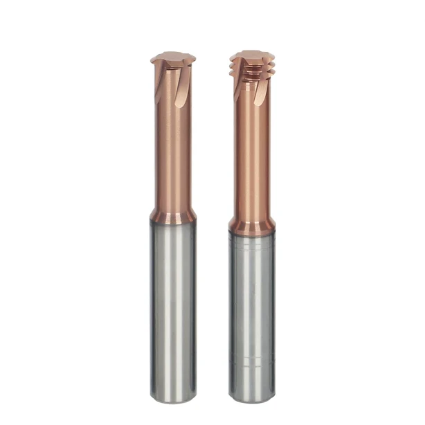
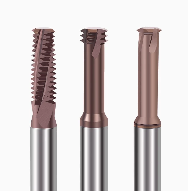
Last month in Stuttgart, Germany, we troubleshot a severe rework issue on a precision mold insert. The part was made of 1.2379 (D2) tool steel, cryogenically hardened to 65 HRC. The print called for a blind M6×1 internal thread. The shop-floor team faced a brutal bottleneck: their ultra-fine-grain carbide threaded end mill snapped before finishing its third hole. The broken carbide fused deep inside the hole, putting a 2,000-euro mold insert at immediate risk of scrap.
Over sixteen years of supporting mold shops across Europe and the US, we have seen this instant-failure scenario repeatedly. Most machinists instinctively blame coating heat resistance, spindle speeds, or tooth feed rates. But analyzing the machine toolpath and spindle load tells a different story. The true root cause is rarely axial pitch or surface speed. It is the overlooked, high-risk variable: thread mill radial depth of cut.
At 65 HRC, steel elongation drops near zero, and cutting resistance spikes exponentially. Widening your radial engagement by just 0.02 mm causes the internal contact arc to expand instantly. Heat can no longer escape with the chip, generating violent thread mill chatter. Trapped between high-frequency harmonics and mechanical impact, the core cross-section of the tool suffers rapid fatigue fracture. Catastrophic tool wear and snapped teeth follow within milliseconds.
When running cnc thread milling on hardened steels, do you really have to crawl at a snail’s pace? Or is your CAM setup simply missing a radial engagement model calibrated for hard-milling loads?
A Real-World Shop-Floor Disaster: Why Do Thread Mills Frequently Break When Machining HRC65 Steel?
We constantly see shops apply pre-hardened steel parameters to cryogenically quenched tool steels. Machinists often split the radial allowance into two equal passes, assuming flood coolant and lower RPM will save the tool. In 65 HRC steel, this assumption is lethal. The dense carbide network leaves no room for plastic deformation. Once radial force passes the critical threshold, it snaps the tool’s structural core instantly.
Spindle load meters confirm that tool failure happens in a fraction of a second. The machine spindle does not stall; the cutting resistance spikes the moment the tool enters the cut. Micron-scale deflection causes unintended chip thickening that compounds on every tooth. If your thread mill radial depth of cut exceeds the elasticity limits of your setup, the tool encounters blunt impact instead of clean shear.
Analyzing Thread Mill Tool Wear and Early-Stage Micro-Chipping: Insights from Broken Tools Returned by Western Clients
Whenever broken tools arrive at our lab, we inspect the leading teeth under an ultra-depth-of-field 3D microscope. Operators typically report abrasive wear or coating failure. However, high-magnification analysis consistently reveals shell-like micro-chipping along the honed cutting edge. This premature thread mill tool wear is not abrasive loss; it is mechanical spalling driven by extreme contact stress.
During hardened steel milling, alternating shear forces overload the sub-micron carbide grain boundaries beneath the coating. Micro-cracks propagate along these boundaries in just a few revolutions. While engineers often debate AlTiN versus silicon nanocomposite coatings, our stance is simple: once micro-chipping starts, no coating can save the edge. You must regulate the mechanical load per tooth.
Rigidity Limits and Cutting Resistance: The Extreme Sensitivity of Thread Milling to Radial Depth of Cut (DOC) in HRC 65 Hardened Steel
At 65 HRC, the shear yield strength of the steel pushes tooling systems to their absolute limits. Every entry cycle tests the static and dynamic rigidity of your holder and spindle. Because internal threads feature an internal concave boundary, the tool-to-bore contact area is significantly larger than in external contouring. Consequently, a tiny surge in thread milling radial DOC triggers an exponential rise in deflection forces.
When working with clients, we balance cycle time against deflection risks. Pushing radial engagement speeds up cycle time, but overhangs beyond 2.5×D induce high-frequency harmonic instability. We always advise taking smaller, incremental radial steps instead of gambling on aggressive cuts. In 65 HRC mold steel, excessive side load causes pitch diameter taper, loud vibration, and catastrophic breakage.
Moving Beyond Single-Pass Machining: Radial Depth of Cut and Multi-Pass Layering Strategies for HRC65 Thread Milling Cutters
In many shops, operators attempt to cut the full thread profile in one or two passes to cut cycle time. While standard steels tolerate aggressive engagement, applying this to hardened die steel is like driving a tool into solid granite. Full-profile engagement spikes cutting forces instantly, twisting the toolholder and spindle assembly. This creates pitch diameter taper and concentrated thermal stress at entry.
Machining 65 HRC workpiece steel demands abandoning the “fewest passes possible” mindset. You must restructure the toolpath into a controlled, multi-pass sequence. Dividing radial step-over keeps shear forces well within the carbide’s elastic threshold. This approach cuts spindle vibration peaks and keeps your hrc65 thread milling cutter running inside a predictable wear window instead of breaking abruptly.
Proven Radial Layering Algorithms: A Decremental Step-Over Model for Thread Milling Hardened Steel
Our field tests on hardened die steels point to a clear rule: use a decremental step-over strategy. As the thread profile forms from the crest to the root, the tool’s contact area expands non-linearly. Equal radial steps dramatically multiply lateral cutting forces on each successive cycle. We implement a proven ratio: 40% stock removal on pass one, 30% on pass two, 20% on pass three, and 10% on the final sizing cut.
When executing thread milling hardened steel routines, calibrate these step-down ratios against your tool overhang and dynamic setup rigidity. Overhangs exceeding 3×D require five or six passes to distribute radial load safely. An extra fifteen seconds of cutting time is negligible. It costs far less than extracting shattered carbide from a ruined die component.
The Pitfall of the “Spring Pass”: Why a Zero-DOC Pass Drastically Reduces Thread Mill Tool Life on HRC65 Steel
Running a spring pass with zero radial depth of cut is standard practice in soft materials to clean up tool deflection. In 65 HRC tool steel, this practice destroys cutting edges. With zero depth, the honed cutting edge cannot penetrate the surface to shear a chip. Instead, the edge rubs against the hardened workpiece under intense friction and pressure.
Microscopic inspections show extreme thermal damage from this dry rubbing action. Localized flash temperatures rapidly delaminate PVD coatings and cause thermal micro-cracking across the edge. This rubbing action severely degrades your thread mill tool life in just one pass. Always maintain a minimum radial stock allowance of 0.010 mm to 0.015 mm on your final pass, or adjust tool radius offsets instead.

Controlling Machine and Tool Rigidity: Managing Radial Engagement to Suppress Thread Milling Chatter
Experienced machinists recognize the distinct acoustic signature of hard milling instability immediately. A high-pitched squeal is followed by surface chatter marks and a snapped tool tip. Halving the spindle speed is a common, flawed reaction. In our experience, lowering speed often drops the cut into a regenerative chatter zone, spiking tool deflection even higher.
Suppressing chatter requires locking down the physical radial engagement boundary. At 65 HRC, cutting forces exploit micro-deflections in the spindle taper, toolholder, and carbide shank. External damping accessories cannot solve this root problem. You must limit the peak cutting force during initial circular entry to stop thread mill chatter before vibration cascades through the machine spindle.
Mitigating Chatter in Thread Milling with Large Radial Overhangs: Fine-Tuning Radial Depth of Cut
Deep mold cavities frequently force tool overhangs past 3×D or 3.5×D, multiplying tool deflection by the cube of that length. In deep blind bores, operators under schedule pressure often keep feeds low but maintain wide radial step-overs. The confined bore prevents chip evacuation, pushing the tool off-center until it rebounds violently.
Our shop-floor fix is simple: drop the radial depth of cut per pass to between 0.015 mm and 0.020 mm. Slicing micro-thin chips slashes the bending moment on the carbide shank. Managing this side force suppresses severe thread mill chatter on long-reach tools, stabilizing cuts that would otherwise break instantly.
Field Calibration Techniques for Overhang Ratios and Arcs of Contact in Internal Thread Milling
Internal thread milling creates a much larger contact arc than external milling because the concave bore curvature wraps around the cutter. If you select a tool diameter too close to the thread’s minor diameter, the contact arc overloads the teeth instantly. This causes immediate chip packing, heat buildup, and severe deflection.
We instruct engineers to keep the tool-to-thread diameter ratio strictly between 65% and 75% for adequate clearance. Pair this sizing with a 90-degree tangential helical entry roll-in path rather than a straight plunge. This ensures a solid carbide threaded end mill enters the cut smoothly, keeping radial forces balanced and preventing taper from entry shock.

Practical Guide for Field Engineers: Setting Key Cutting Parameters for CNC Thread Milling of HRC65 Hardened Steel
Machinists hit a wall when machining 65 HRC tool steel with stock CAM templates. Hard-part cutting allows zero parameter error. Excessive surface footage triggers extreme friction temperatures, accelerating coating degradation and thermal breakdown. Conversely, an overly conservative chip load fails to shear the material cleanly. This causes immediate work hardening along the bore wall, accelerating flank wear.
On European and American shop floors, our team uses a disciplined rule: cap surface speed first, then tune chip load to stabilize forces. Cutting extreme alloys requires balancing chip heat evacuation against spindle servo dynamics. Your radial depth and feed rate must align with available low-RPM spindle torque. Applying an engineered protocol for cnc thread milling keeps tool breakages to an absolute minimum.
From Spindle Speed to Feed Compensation: A Dynamic Balancing Framework for Thread Milling Parameters
Machinists often treat handbook speed recommendations as gospel. For 65 HRC steel, we keep cutting speeds within a conservative window of 35 to 55 m/min to avoid thermal edge softening. The true challenge lies in calibrating feed per tooth. The chip load must stay above the 0.008 mm micro-shearing minimum, yet remain well below the tool tooth’s bending yield point.
Our dynamic framework for thread milling cutting parameters balances cutting tool survival against cycle time. If chips appear black and powdery, or if spindle load fluctuates past 15%, drop your cutting speed by 10% immediately. Then, adjust chip load until cutting harmonics smooth out into a clean hum. Dynamic tuning at the machine console consistently beats static chart values.
Feed Rate Calculations for External-Approach Helical Interpolation in CNC Thread Milling
A frequent programming oversight in internal threading is feeding the tool based on linear edge speed. CNC controls command the centerline of the tool, not the outer cutting periphery. Because the tool center travels along a smaller internal radius than the actual cutting diameter, the uncompensated edge feed spikes dramatically. Uncorrected code overloads the tool teeth and causes catastrophic tool failure.
Programmers must scale toolpath center feed based on the ratio between the minor bore diameter and tool diameter. Additionally, never enter a cut along a straight 90-degree vector. Always program a tangential, 90-degree helical roll-in move. This circular entry ramps cutting resistance smoothly from zero to target load, eliminating the destructive entry spikes common in cnc thread milling.

A Perspective from Manufacturing and After-Sales Support: Maximizing Thread Mill Tool Life through Process Monitoring
Decades in cutting tool manufacturing taught us a crucial rule: cost-effective machining comes from predictable tool indexing, not running end mills to destruction. In 65 HRC tool steels, even optimal multi-pass strategies rely on active process monitoring. Tuning into changes in spindle harmonics, micro-chatter, and subtle tool deflection allows you to intervene before a catastrophic snap.
Premature tool failures typically trace back to thermal fatigue and cyclical bending loads exceeding carbide limits. If you face high scrap rates on hardened dies, implement closed-loop process tracking right away. Correlating thread pitch accuracy with microscopic edge inspection converts reactive downtime into controlled production. This disciplined routine remains the most dependable method to extend thread mill tool life.
Using Thread Go/No-Go Gauges to Diagnose Overcutting or Tool Deflection (Radial Depth of Cut Issues)
Thread plug gauges act as sensitive load sensors on the shop floor. When a Go gauge binds or a No-Go gauge enters loose, operators frequently adjust wear offsets blindly. In reality, this indicates severe tool deflection. Radial side loads push the cutter off-center, producing a tapered pitch diameter that is narrow at the bottom. Compensating offsets without addressing deflection causes overcutting at the hole entrance.
If a Go gauge binds after two or three turns in a hardened blind hole, stop and inspect your radial pass distribution. Check if your final thread mill radial depth of cut is overloading the tool shank. Reducing final pass radial engagement by 0.010 mm while nudging radial offset clears taper immediately. Reading gauge resistance diagnoses radial deflection far better than trial-and-error offset shifts.
Monitoring Coating Condition and Managing Coolant/Lubrication to Extend Thread Mill Life
Flank wear land width is your primary baseline metric when milling hardened steels. Extreme contact stresses generate friction heat that strips coatings, leaving exposed carbide to degrade within minutes. Many shops flood the hole with water-soluble coolant. In 65 HRC steel, thermal shock from high-pressure liquid triggers micro-cracking; high-pressure dry air or MQL delivers far more consistent tool life.
If tool life stalls on your hardened threading jobs, inspect your cutting edges with a 20× loupe. Micro-spalling along the honed edge or flank wear past 0.1 mm indicates that your solid carbide threaded end mill has reached its retirement point. If you deal with difficult hardened components, complex deep blind holes, or batch breakages, share your print and alloy details so we can dial in your toolpaths together.