Last month, we troubleshot a recurring failure on a 5-axis vertical machining center at a Tier-1 automotive mold shop in Michigan. The setup was milling M5 internal threads in vacuum heat-treated D2 tool steel at HRC62. By the eighth hole, the tool tips suffered catastrophic fracture. The shop engineer had lowered the cutting speed (Vc) and dropped the feed rate to a crawl, but the flank faces burned and snapped even faster.
Under our 200x optical microscope, the crack patterns told the real story. This was not abrasive flank wear from high surface footage. It was mechanical impact fatigue caused by a fundamental imbalance in the thread milling axial depth of cut during helical interpolation. Crossing HRC60 spikes metal shear resistance non-linearly. In these setups, even a tiny deflection in a solid carbide thread mill creates severe chatter.
In past decades supporting precision shops across North America and Europe, we have seen this failure pattern repeatedly. Many programmers accustomed to 40–50 HRC pre-hardened steels assume reducing radial cut width (ae) is enough. At HRC62, however, cutting forces concentrate heavily along the cutting edge. That localized stress easily exceeds the transverse rupture strength of standard carbide grades.
When facing extreme hardness, should you risk a single-pass full-depth cut, or switch to thread milling multiple passes to distribute the axial load? How do you hold micron-level thread tolerances without sacrificing tool life or cycle time? The answer comes down to controlling tool deflection, managing chip load, and respecting the machine setup’s rigidity.
Why Is the Axial Depth of Cut Often the Primary Culprit Behind Tool Chipping in HRC62 Steel?
Machining cold-work tool steels above HRC60 exposes the limits of standard shop-floor habits. Many programmers drop spindle speed but maintain deep axial engagement, forgetting that shear yield stress in hardened martensite escalates non-linearly. When the axial contact span is too wide, resultant radial and axial forces easily exceed the transverse rupture strength of the carbide substrate.
Across our field calls in North America and Europe, we see this miscalculation daily. Excessive thread milling axial depth under multi-tooth engagement creates minute elastic hysteresis in the tool shank. As each flute enters and exits the cut, intense cyclic shock shatters the protective coating within milliseconds. This impact initiates sub-micron fatigue cracks long before standard abrasive wear can develop.
Real-World Failure Mechanisms in CNC Thread Milling Bits: Micro-Chipping vs. Rapid Flank Wear
During a tooling audit at an injection mold shop in Stuttgart, technicians blamed premature tool failure on poor coating adhesion. However, inspection of the worn CNC thread milling bit under a 3D digital microscope showed zero abrasive scoring on the relief face. Instead, the leading tooth showed distinct micro-chipping along the cutting edge. Mechanical shock load—not thermal friction—had destroyed the tool.
Distinguishing these two failure modes is essential on the shop floor. In HRC62 steel, a balanced depth of cut produces a uniform, polished wear band across the flank. If axial force spikes at entry, the honed edge notches instantly. Because the workpiece offers zero ductility, those micro-notches block chip evacuation and cause complete tooth failure on the very next pass.
Radial Layering and the Mechanical Equilibrium of Axial Depth: Why Hardened Steel Defies Mild Steel Math
Mild steels and aluminum allow reliable chip-load calculation because plastic deformation carries thermal energy out with the chip. HRC62 tool steel behaves completely differently. The material generates no continuous curly chips, producing only fine, abrasive particulate dust. Cutting resistance is transmitted entirely through rigid mechanical contact, meaning standard feed-per-tooth formulas simply do not apply.
Our dynamometer test data reveals a sensitive balance between radial engagement (ae) and thread milling axial depth. Forcing full depth in one pass demands reducing radial cut width below 0.02 mm. At that point, the edge rubs and burnishes rather than shears, triggering severe work hardening. Reducing the axial cut increment lets you maintain an aggressive radial shear load, keeping cutting forces inside the safe compressive stress zone.
The Tipping Point for Tool Failure: Full-Depth Single-Pass vs. Incremental Multi-Pass Strategies
Can you cut full thread depth in a single helical pass in HRC62 steel? The answer depends on your acceptable tool replacement cost. While optimizing an orthopedic bone-plate setup running HRC62 material, we tracked tool mortality closely. Milling blind holes with an axial engagement exceeding 1.5 times the thread pitch caused tooth fractures reliably between holes 12 and 15.
We solved the bottleneck by replacing the full-depth path with thread milling multiple passes, dividing the stock axially and radially. For cutters between 4 mm and 8 mm, capping the axial step to a single thread pitch (1*P) pushed tool life past 80 finished holes. Trading a few extra seconds of machine cycle time eliminates emergency tool changes and delivers true process stability.

Selection and Geometric Considerations for Solid Carbide Thread Mills for HRC62 Steel
When threading high-hardness alloys, many machinists instinctively tweak feed rates or spindle speeds first. If your core tool geometry is wrong, surface-level parameter tweaks will not save your setup. Crossing HRC60 amplifies every geometric flaw under extreme shear stresses. Flute designs and rake angles that perform reliably on pre-hardened steels become structural failure points in cold-work tool steel.
Our technical support work across European precision toolrooms shows that success hinges on balancing substrate rigidity, edge micro-geometry, and thermal stability. When running a solid carbide thread mill on HRC62 dies, abandon extreme sharpness and full-length contact. Tool geometry must absorb mechanical shock on entry and channel severe cutting stresses safely into the tool shank.
Ultra-Fine-Grain Substrates and Oxidation-Resistant Coatings: The Foundational Barrier for Extending Tool Life
Substrate grain structure dictates whether your tool can survive severe cyclic mechanical loading. In our fracture-load lab tests, cobalt content above 10% caused carbide to deform plastically under extreme cutting zone heat. Conversely, dropping cobalt too low creates brittle edges that shatter on contact. We rely on sub-micron (0.2–0.4 μm) tungsten carbide with an 8% binder to keep the cutting edge rigid and intact.
Coatings must handle intense thermal barriers when milling dry or with minimal quantity lubrication (MQL). Contact zone temperatures routinely exceed 900°C, stripping standard single-layer TiAlN coatings instantly. We recommend nanocomposite AlTiSiN formulations that generate a dense aluminum-oxide barrier at heat. High-adhesion coatings protect the edge and maximize thread milling tool life in sustained production runs.
Managing Overhang and Core Thickness: Why We Recommend Short-Flute, Long-Shank Solid Carbide Thread Mills for Hardened Steel
Many programmers favor full-profile thread mills to finish internal threads in a single pass. However, tool deflection scales with the cube of the overhang length under heavy lateral loads. Engaging full flute length in HRC62 steel spikes cutting forces instantly across multiple teeth. A deflection of just 5 microns creates severe taper error and destroys the tool through chatter.
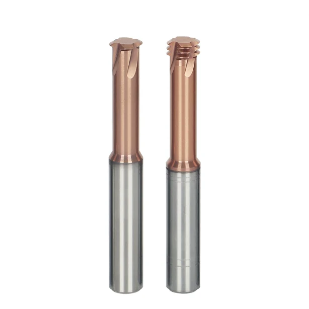
In our field designs, we consistently specify short-flute tools with 3 to 5 active teeth backed by a reinforced neck relief. This robust core geometry gives the solid carbide thread mill maximum bending and torsional stiffness. Taking an incremental step-down approach may add seconds to the cycle, but it eliminates emergency downtime and scrapped parts.
Practical Pitfalls in Deep Blind-Hole Machining: Chip Evacuation and the Critical Role of High-Pressure Through-Tool Coolant
Blind-hole threading in hardened tool steel carries a severe risk of chip recutting. Martensitic chips from HRC62 steel fracture into razor-sharp, abrasive micro-dust rather than continuous curls. External flood nozzles cannot pierce the swirling air barrier once depth exceeds 1.5D. Trapped debris packs the hole bottom, and the bottom tooth fractures the moment it crushes those hardened particles.
We strongly advise utilizing high-pressure through-spindle delivery for deep blind holes. Delivering 40+ bar coolant or high-pressure dry blast air straight through the tool tip evacuates chips continuously. Directing high-pressure blast air into the cut clears abrasive swarf upward out of the flutes. This clean evacuation protects bottom teeth and guarantees process security during thread milling hardened steel.

Mastering Deep-Hole and Miniature Thread Milling: Rigidity and Deflection Compensation in Axial Machining
Threading below M6 in HRC62 materials completely changes the structural physics of the cut. Larger tools absorb cantilever loads easily, but miniature thread mills have core diameters of only 2 to 4 mm. Their section modulus drops exponentially, making them extremely susceptible to bending. Any spike in cutting resistance converts directly into tool deflection and thread profile distortion.
Our field experience setting up aerospace fastener and orthopedic implant runs shows that high-end CNC dynamic response alone cannot prevent deflection. Cutting edges inevitably flex while shearing hardened material at micro-scales. You must integrate calculated taper compensation and axial relief directly into your CAM toolpath and controller offsets to prevent snapping a small diameter thread mill.
Axial Machining with Small-Diameter Thread Mills (Below M6): Calculating Tool Deflection at the Tip for Length-to-Diameter Ratios Exceeding 2.5
Milling M4 or M5 blind holes at depth-to-diameter ratios beyond 2.5D often yields tapered threads that fail the “go” plug gauge. Operators frequently bump the global radial tool offset ($D$-value), which overcuts the thread entrance and scraps the part. Cantilever deflection peaks at the hole bottom, where the tool tip experiences the highest cutting resistance and flexes away from the wall.
Rather than relying on flat offsets, we calculate dynamic compensation curves directly in the G-code. When programming a small diameter thread mill, we divide the axial interpolation path into two or three vertical zones. Incrementally expanding the programmed radius by 0.006 to 0.012 mm near the hole bottom neutralizes deflection. This proven correction restores true pitch-diameter cylindrical tolerance from top to bottom.
Rigorous Control of Thread Milling Depth Tolerance: Practical Strategies to Prevent Bottom-Hole Interference and Tapered Thread Crests
Thread clearances in precision HRC62 cavity inserts are held to tight margins. While thread mills cut closer to hole bottoms than conventional taps, drill point tapers and thermal movement leave zero room for error. If the bottom teeth kiss the tapered drill floor, the sudden axial collision instantly shatters the carbide shank.
Maintaining strict thread milling depth tolerance requires syncing hole depth measurements with the Z-axis program datum. We enforce a clearance floor of at least 0.5 times the thread pitch above the drill point. Additionally, set laser tool-setter routines to check for axial pullout and thermal growth in 0.005 mm increments to prevent bottom-hole collisions.
Adjusting Entry and Exit Arcs for Helical Interpolation in Thread Milling of Quenched and Tempered Materials
Most carbide failures occur during tool engagement or disengagement rather than the main helical cut. Plunging radially or using an abrupt linear lead-in creates violent mechanical shock against HRC62 material. Pausing on exit is equally destructive: elastic springback pinches the relief face, causing micro-chipping along the trailing edge.
We always program 90-degree or 180-degree smooth helical roll-in arcs combined with active axial travel during entry. This dynamic 3D spiral ramps the chip load progressively from zero to the target feed per tooth. Smooth rolling entry eliminates entry chatter, ensures quiet cutting, and delivers the level of stability required for thread milling HRC62 steel.

Field Programming and Practical Application: Multi-Pass Thread Milling Strategies and Tool Life Optimization
Once your machine rigidity and tool selection are dialed in, production reliability in HRC62 steel comes down to toolpath architecture. Operators chasing quick cycle times often cut non-cutting rapids, then plunge full-profile into solid stock. At HRC62, high grain-boundary shear resistance creates severe cyclic fatigue on every pass. An aggressive, single-pass cut guarantees premature edge chipping and machine downtime.
Predictable tool wear requires breaking up the cut to eliminate sharp cutting-force spikes. In mold shops across North America and Europe, structured multi-pass milling reduces cantilever deflection and delays micro-chipping. While extra interpolation passes add a few seconds per hole, they eliminate broken tools, EDM burnouts, and frequent tool resets. That reliability routinely doubles overall batch throughput.
Moving Beyond the Single Pass: Establishing a Robust Multi-Pass Thread Milling Matrix with Radial Step-Down and Axial Increments
Equal radial step-downs—such as three equal 0.2 mm passes for a 0.6 mm depth—are a common trap on the shop floor. As the cut progresses outward, contact arc length expands, causing lateral cutting pressure to spike on later passes. In HRC62 mold blocks, we mandate a diminishing radial step-down: take 50% to 60% of total stock on pass one, 25% to 30% on pass two, and save a light finish load for pass three.
For deeper holes with longer overhang, we layer an axial step-down into the routine. Splitting the operation into thread milling multiple passes keeps cutting forces confined to a narrow, rigid contact zone. This prevents simultaneous shear overload along the entire cutting edge. Stepped entry suppresses chatter spikes upon engagement, keeping cutting forces well inside the carbide’s elastic limit.
Critical Cutting Parameters for Thread Milling Hardened Steel: Avoiding Rubbing with Minimum Surface Footage and Feed per Tooth
Operators facing HRC60+ materials often drop spindle speed and crawl feed rates out of caution, but that almost always backfires. Solid carbide tools rely on localized shear-zone heat to soften hardened material. If cutting speed drops below 45 m/min, the steel refuses to shear cleanly, turning the cut into cold, abrasive pounding. We hold surface speeds between 55 and 75 m/min to maintain shear plasticity without overheating the coating.
Feed per tooth (fz) has a strict lower threshold when thread milling hardened steel. Every cutting edge features a microscopic honed edge radius. If programmed feed falls below that radius (under 0.005 mm/tooth), the edge burnishes and rubs instead of shearing. That friction causes severe work hardening and destroys flank faces in seconds. Keep fz between 0.015 and 0.03 mm/tooth to ensure genuine shearing.
Eliminating Elastic Deflection in the Final Pass: The Role of a Spring Pass in Meeting Thread Gauge Requirements
A common issue on HRC62 parts is a thread that accepts a “go” gauge at the mouth but binds tight toward the bottom. This is rarely a radius offset calculation error; it is cantilever shank deflection under heavy side load. Because hardened steel exhibits high elastic recovery, pushed-aside material springs back onto the pitch diameter and flank walls, leaving micron-scale taper errors.
The cleanest fix is a zero-depth spring pass that repeats the final finish path at identical programmed coordinates. It takes no nominal cut; it only removes elastic spring-back and deflection stock left behind by the prior pass. Running a dedicated spring pass eliminates micro-stepping from thread milling multiple passes, locks pitch diameter inside tolerance, and ensures the “go” gauge spins through smoothly while the “no-go” gauge stops clean.

Field Data from Europe and the U.S.: A Process Review—From 30 Scrapped Holes to Stable Production of 180 Holes
Lab cutting data rarely survives contact with production-floor dynamics. When optimizing customer jobs across Europe and North America, we track spindle load, tool failure rates, and actual shift output. In HRC62 steel, parameter tweaks are not about chasing mirror finishes on test coupons. They are about creating a wide industrial process window that tolerates machine vibration, minor tool deflection, and severe material hardness.
Substrate grain selection, stubby flutes, deflection offsets, and radial stepping are just theory until verified on a spindle. Tying these rules directly to your thread milling axial depth of cut turns a high-scrap bottleneck into a stable, lights-out process. The production data below illustrates how restructuring axial engagement transforms tool economics on hardened mold tooling.
Comparison of Machine Setup Parameters for a Medical Mold Component (D2/1.2379, Hardened to HRC62)
We troubleshot this setup at an orthopedic tooling facility in Minnesota running vacuum-hardened 1.2379 (AISI D2) at HRC62. The shop used full-flute tools to cut M4 blind holes in one pass, chipping teeth after only 25 to 30 holes. Operators were trapped monitoring the spindle full-time. We re-engineered tool selection, coolant delivery, and step-downs to build a reliable production baseline:
| Machining Parameter / Metric | Original Shop Setup | Optimized Process Solution |
| Tool Type & Geometry | Full-profile miniature mill (3D reach) | 3-tooth stub-flute solid carbide thread mill |
| Cutting Speed (Vc) | 42 m/min (insufficient shear heat) | 65 m/min (stable plastic shear zone) |
| Feed per Tooth (fz) | 0.008 mm/tooth (edge-rubbing zone) | 0.022 mm/tooth (positive chip formation) |
| Pass Strategy | Single-pass full-depth helical interpolation |
3 radial passes (55% / 30% / 15%) + 1 spring pass
|
| Coolant / Evacuation | External flood water-soluble coolant | 50 bar through-spindle dry air blast |
| Tool Life (Holes per Tool) | 28–32 holes (brittle tooth fracture) | 180–200 holes (predictable flank wear) |
While cycle time per hole rose from 14 to 26 seconds, gross daily output jumped nearly 40% over two shifts. Eliminating broken tools ended line stoppages, workpiece annealing, fragment EDM burning, and repeated tool touch-offs.
From Tool Breakage and Downtime to Unattended Machining: Reducing Total Cutting Costs via Controlled Axial Depth
If you are fighting broken tools in HRC60+ steel, or dealing with tapered pitch diameters where “go” gauges seize up, take a hard look at your process. Are you forcing a single-pass full-depth cut to save ten seconds? Is your chip load so low that the flutes rub rather than cut? Are chips trapped in blind holes because of weak external coolant pressure?
In ultra-hard metals, disciplined multi-pass cuts are the fastest route to reliable delivery. By tightly controlling your thread milling axial depth, you remove destructive bending moments from the shank and free operators from constant fire-fighting. If you are struggling with tough alloys, tight pitch tolerances, or long overhangs, review your cutting data, part prints, and worn-tool photos. Often, a simple path adjustment or offset fix is all it takes to solve the issue for good.