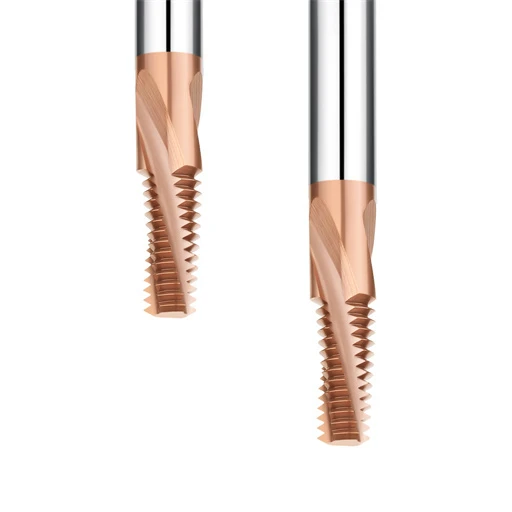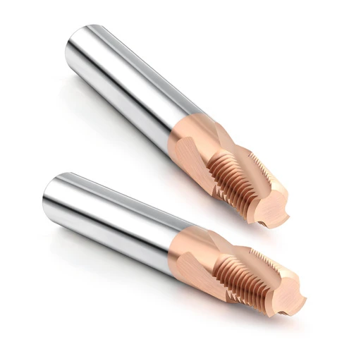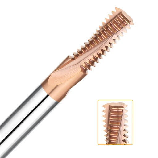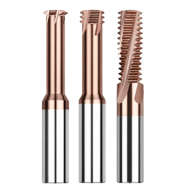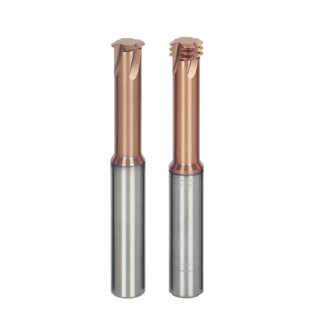

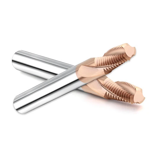
Last month, we assisted an automotive stamping die manufacturer in Stuttgart, Germany, with a critical failure on their shop floor. A set of SKD11 progressive die inserts—valued at over €40,000—failed during the finish-milling of M10×1.5 threads after heat treatment to HRC 60. Less than three seconds after the operator started the cycle on a five-axis machining center, a piercing shriek cut through the shop. The custom carbide cutter snapped radially at the pilot hole entrance, wedging the broken shank inside the hardened cavity.
Over the past 16 years of providing tooling support and on-site troubleshooting across Europe and North America, we have seen this scenario play out almost quarterly.
Many machinists handle pre-hardened steels like P20 or 42CrMo4 with ease. But once workpiece hardness crosses HRC 55, standard programming habits turn into tool-breaking traps. The root cause is rarely poor carbide grade or insufficient machine rigidity. Instead, the default CNC thread milling parameters exported straight from CAM software fail to account for the dynamic feed compensation required during internal thread circular interpolation.
A look into the motion control logic of Heidenhain or Fanuc systems reveals three physical realities often overlooked on the shop floor:
-
Centerline vs. Edge Feed Discrepancy: Machine controllers manage the path of the tool center point (Feed-to-Center). During thread milling circular interpolation in small bores, the actual feed per tooth at the outer cutting edge can surge to two or three times the programmed rate.
-
Chip Load and Work-Hardening: Quenched alloy tool steels have near-zero plastic ductility. A minute error in chip load causes the tool tip to rub rather than shear. This instantly work-hardens the surface and destroys the thread milling cutter within 0.1 seconds under fluctuating radial loads.
-
Abrupt Toolpath Transitions: Straight radial plunge moves into hardened steel cause high-impact mechanical shock. An unoptimized thread milling toolpath spikes cutting forces to thousands of Newtons, instantly shattering delicate carbide edges.
Achieving micron-level thread milling tolerance control while protecting tool life requires balancing mechanical stability with kinematics.
When working with an HRC 60 die insert that leaves zero margin for scrap, are you certain the feed rate on your digital readout matches what your tool tip actually feels during a G02/G03 helical interpolation move?

Why Do Standard Thread Milling Parameters Frequently Lead to Tool Breakage on HRC 55+ Workpieces? — Field Failure Analysis and Tool Selection
We have analyzed dozens of broken tools from heat-treated jobs across the US and Europe. Fractured shanks almost always show a clean 45-degree torsional shear failure. Soft steels and aluminum allow elastic give to absorb feed surges, but materials above HRC 55 eliminate all tool clearance. Yield strength and cutting forces spike together. Default CAM values instantly overload the transverse rupture strength of ultrafine carbide substrates.
Do not rely on cutting sounds or sparks to judge tool engagement on hard parts. By the time you hear high-frequency chatter, the cutting edge has already micro-chipped several revolutions earlier. Microscopic inspection reveals that early failure starts with micro-spalling from dynamic impact. Frictional heat then rapidly strips the physical coating, causing the tool to seize. Eliminating breakage requires matching your parameters to the material’s metallurgy and contact mechanics.
Lessons from Scrapped SKD11 and D2 Dies: Why Quenched Steels Reject Standard Milling Feeds
During a technical audit at an Ohio die shop, an entire batch of HRC 60 SKD11 and D2 die inserts was scrapped due to stripped threads. The machine log showed the programmer had reused their standard P20 feed strategy, merely dropping the spindle speed by 30% at the control panel. This shortcut ruined the chip-load-per-tooth ratio. Without radial feed compensation, it triggered severe cold-work hardening across the holes.
Quenched D2 and SKD11 matrices are packed with hard, abrasive chromium carbides. The tool edge repeatedly collides with these ultra-hard phases at high speed. Direct application of standard parameters either overloads the tooth edge or causes the tip to burnish the surface. This narrow operating window is why process engineers must avoid generic parameters when running thread milling SKD11 jobs.
Thread Milling HRC60 Hardened Steel: Full-Profile or Single-Tooth Cutters?
Machining near HRC 60 always sparks debate over multi-tooth (comb-style) versus single-tooth cutters. Full-profile tools sound ideal because they finish a complete thread depth in a single 360-degree helical pass. However, multiple cutting edges engaging simultaneously multiply radial cutting pressure. If your machine spindle deflects even a few microns, the cutter binds instantly and fractures across all flutes.
Our field tests favor single-tooth or low-tooth-count (under three teeth) designs for HRC60 hardened steel thread milling. Single-tooth paths take slightly longer to complete, but they isolate cutting forces to a single point. This eliminates tool chatter and protects expensive, one-off die inserts. On hard materials, process security always outweighs saving thirty seconds of cycle time.
Controlling Runout and Overhang for Threaded End Mills: Western Shop Standards
High-end mold facilities maintain tool clamping runout with absolute discipline. In soft machining, 0.01 mm of radial runout only causes slight tool wear. Above HRC 58, depth of cut is often only a few microns; a runout of just 0.008 mm forces a single tooth to take 100% of the cutting load. That single overloaded tooth micro-chips, and the remaining teeth fail immediately after.
For this reason, we forbid standard ER collet chucks on any long-reach threaded end mill. We require high-precision hydraulic holders or shrink-fit systems. Maintain dynamic radial runout under 3 microns (0.003 mm) at the tool tip, with tool overhang kept below 3x diameter. If deep pockets require longer reach, select tapered heavy-metal or carbide-reinforced shanks to maintain system rigidity before touching the feed controls.
Core Interpolation Feed Calculation: Preventing Discrepancies Between Machine Linear Feed and Arc-Path Cutting Feed
We regularly see operators stare in disbelief at broken cutters, insisting they programmed the catalog feed per tooth of 0.03 mm. What they miss is a basic kinematic rule: during linear cuts, the tool-center feed matches the cutting-edge velocity. Inside small internal bores, however, the outer edge sweeps a much longer arc than the center line. Without constant surface speed compensation, the machine defaults to tool-center trajectory, causing the cutting edge to take massive, uncontrolled bites.
In steels harder than HRC 55, this geometric error destroys cutting tools. Quenched materials offer zero plastic deformation, so cutting forces spike exponentially under excessive loads. The slightest overfeed induces violent chatter that shatters solid carbide teeth on initial contact. Whenever we set up internal helical cuts, our first rule is simple: convert the programmed feed from the machine’s default center path to the true cutting-edge profile.
Feed Correction Formula for Thread Milling Interpolation: Calculating the Actual Tool Center Path
During field troubleshooting, we always check the programmed F-value directly on the machine screen. In internal helical moves, the tool center travels along a compressed radius equal to the hole radius minus the tool radius. If you do not scale down the control-panel feed rate, the outer edge will overcut drastically. The formula is straightforward: multiply the target edge feed by the difference between the thread major diameter and the tool diameter, then divide by the thread major diameter.
At a North American aerospace shop milling HRC 58 die steel, the team ran a 6 mm cutter in an M10 hole at 120 mm/min. Applying our thread milling interpolation formula showed their commanded tool-center feed had to drop to 48 mm/min. This cut out 60% of their inflated feed rate. The spindle screaming stopped instantly, and the cutter—which previously chipped after two holes—finished the entire production run without wear.
Calibrating Effective Chip Thickness (hex) in Internal Thread Milling: Eliminating Work Hardening
Radial depth of cut (ae) in thread milling is tiny—often just a few hundredths of a millimeter. This geometry causes severe chip thinning, compressing the maximum undeformed chip thickness (h-ex). If an engineer tries to protect the tool by dropping feed too low, the effective chip thickness drops below the cutting edge’s honed radius (typically 4 to 8 microns). The teeth stop cutting and begin burnishing the steel.
SEM imaging at a European client’s plant confirmed that severe rubbing drives temperatures past the phase-transformation point. Doused in coolant, the surface instantly forms a brittle “white layer” exceeding HRC 65. The next tooth strikes this hardened skin like solid diamond, chipping immediately. We prevent this by ensuring nominal feed stays high enough so h_ex always clears the hone radius, stopping work hardening before it starts.
Look-ahead and Acceleration/Deceleration Settings for Thread Milling Circular Interpolation on Western CNCs
Even perfect formulas fail if machine servos mismanage circular transitions. Different control systems handle tight corner acceleration with varying priorities. Haas controls, for example, often default to path smoothing. If you run hardened steel without configuring the G187 accuracy command correctly, the servos can lag slightly upon entry, causing a micro-hesitation and gouge that snaps delicate carbide tips.
On Heidenhain controls running thread milling circular interpolation, we activate Cycle 32 tolerance cycles with look-ahead feed optimization. M109 and M110 commands automatically handle constant cutting-edge speed, removing manual math. When enabling High-Speed Machining (HSC), always bias parameters toward contour accuracy over speed. Sacrificing 5% cycle time is far better than risking position-loop overshoot on small internal arcs.
Trajectory Strategies to Prevent Chipping: Optimizing Thread Milling Toolpaths and Entry/Exit Details
Feed algorithms control steady-state loads, but trajectory planning determines whether a cutting edge survives entry and exit. Steel above HRC 55 lacks the ductility to absorb sudden mechanical shocks. Any abrupt curvature shift in the toolpath sends destructive stress waves directly through the cutter edge. Standard practices that run safely in annealed steels will snap carbide teeth in quenched tool steels.
Over 80% of tool failures occur in the first few milliseconds of contact or during final center retracts. To stop edge chipping, convert harsh perpendicular hits into smooth, continuous load curves. Fine-tuning the lead-in arc and radial step-overs in your thread milling toolpath keeps cutting forces inside the safe elastic zone of micro-grain carbide.
Eliminating Radial Plunge Cuts: Implementing Roll-in/Roll-out Thread Milling Toolpath Strategies
Programmers sometimes plunge straight along the X or Y axis into hole walls to save programming time. On hardened steel, this direct impact destroys tools. Straight entry forces the contact angle from zero to maximum instantly, spiking cutting resistance. Our dynamic dynamometer tests show perpendicular plunge forces reach four times steady-state cutting loads, initiating micro-fractures in the tool substrate.
We enforce smooth roll-in and roll-out helical arcs on all hardened jobs. A 90-degree quarter-circle entry works well when hole bottoms have tight clearances. Where depth allows, a 180-degree semi-circular entry is even better. This smooth thread milling toolpath gradually ramps radial engagement and chip thickness from zero to target depth, absorbing impact shocks and preserving fragile tooth tips.
Multi-Pass Strategies for HRC60 Hardened Steel Thread Milling Toolpath: Incremental Radial Passes
Taking full thread depth in a single pass on HRC 60 steel is a reckless shortcut. Full-profile engagement generates massive radial deflection on slender shanks, cutting tapered threads and risking total tool breakage. Stepping down radial engagement across multiple passes is standard practice in our facilities to protect critical tooling and expensive workpieces.
Avoid dividing depth into equal fractions, since tooth contact area expands as you cut deeper into the thread profile. When building an HRC60 hardened steel thread milling toolpath, use percentage-based step reductions: take 50% to 60% on the roughing pass, 30% on the semi-finish pass, and 10% on the final spring pass. This descending load curve stabilizes thread pitch diameter while keeping cutting teeth sharp.
Climb Milling or Conventional Milling? Managing Chip Evacuation and Edge Stress
We almost always choose climb milling on high-hardness workpieces. Climb milling cuts thick-to-thin: the tooth enters at maximum chip thickness and exits at zero, pressing the part firmly against the fixture. This entry geometry eliminates rubbing and burnishing, preventing friction heat from degrading the PVD coating or dulling the cutting edge prematurely.
Conventional milling starts at zero chip thickness, forcing the edge to rub against work-hardened material before shearing begins, which induces chatter. The only exception occurs in deep blind holes where upward climb milling traps hot chips at the bottom. In those rare cases, we modify tool direction and clear chips with high-pressure air blast. Beyond that constraint, climb milling remains the superior method for hard-material processing.
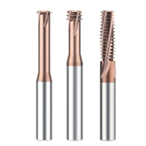
Balancing Tight Tolerances with Long Tool Life: Thread Milling Tolerance Control and On-Site Adjustment
Interpolation formulas and roll-in paths mean nothing if your parts fail thread gage inspection. Many European and American shops we visit face the same bottleneck: operators repeatedly test-cut to chase pitch diameter tolerances, inducing thermal drift and premature edge wear. Others dial down feed rates to preserve tool life, which causes cutter deflection and severe pitch taper. In steels above HRC 55, a deflection of just two microns consumes your entire dimensional tolerance zone.
Achieving repeatable tolerance and tool life requires a systematic adjustment routine, not operator guesswork. Our approach to thread milling tolerance control decouples heavy chip shearing from final profile sizing. By applying a controlled compensation cycle on the controller, we quantify tool deflection and offset it directly. This removes the uncertainty of go-gages binding and no-go gages failing during volume production.
Ensuring 6H and 2B Tolerances: A Two-Pass Thread Milling Strategy for Minor Deflection
Pitch diameter tolerance bands for 6H metric and 2B imperial internal threads measure only a few tens of microns. Even in high-rigidity holders, cutting forces from quenched steel push slender tool shanks radially. The resulting thread passes the gage at the chamfer but binds midway down the bore. To hold strict limits, we run a two-pass cutting sequence: the first pass clears 90% of the material, while the second spring pass cuts the true profile under minimal radial force.
If you are threading deep blind holes in hardened steel and your go-gage consistently jams halfway down, you can eliminate shank deflection with this two-pass routine. Leave a radial finish stock of 0.01 mm to 0.02 mm for that second pass. This reliable thread milling tolerance control method removes residual bending moments from the shank, delivers straight thread walls, and clears minor burrs in a single setup.
On-Site Tool Wear Compensation: Using Wear Offsets Instead of Editing CAM Code
In fast-paced production cells, machinists often stop the spindle, re-open CAM software, and re-post NC code just to expand pitch diameter by a few microns. This practice wastes machine cycle time and introduces post-processor syntax errors. As long as your program uses standard G41/G42 radius cutter compensation, the CNC wear offset table provides the fastest, safest adjustment mechanism directly at the control panel.
If your go-gage fits too tightly during inspection, enter a negative wear value such as -0.005 mm into the tool compensation register. The controller instantly shifts the tool path outward during circular interpolation. As micro-grain coatings wear gradually, adjusting machine wear offsets compensates for dimensional drift without stopping the production run, letting you extract full tool life from every premium solid carbide cutter.
Case Study: Root-Cause Fix for Deep-Hole Thread Milling SKD11 (HRC 60–62)
At a North American medical mold facility, operators struggled with catastrophic tool breakage in M6×1.0 blind holes. The workpiece was vacuum-hardened SKD11 tool steel at HRC 60–62 with a thread depth of 15 mm (2.5×D). The original process used a two-flute straight-tooth cutter with a direct radial plunge. Cutters snapped every two to three holes, loading broken carbide into expensive cavity inserts.
We rebuilt the tooling package from scratch, replacing the tool with a thick-core single-plane cutter and reprogramming a 180-degree roll-in helical lead-in. We then established a two-pass strategy with dedicated wear offset increments designed specifically for thread milling hardened steel SKD11 tooling. Tool life surged from 2 holes to over 45 holes per tool, holding repeatable 6H thread tolerances. If you are struggling with thread milling in quenched tool steels, send us your part prints, hardness data, and spindle specs—we will help you dial in a crash-proof process.