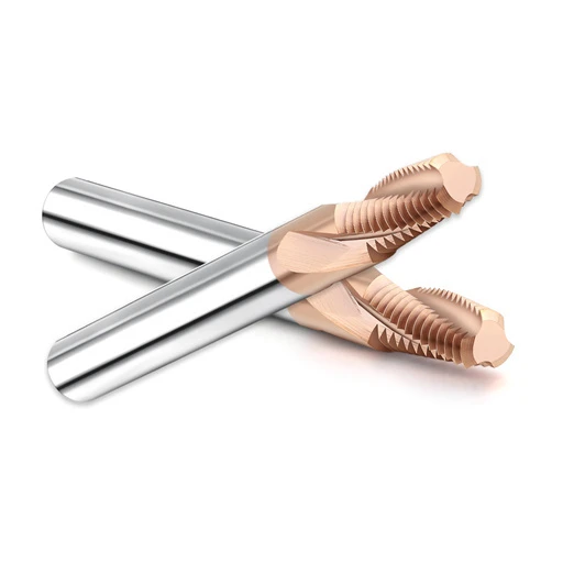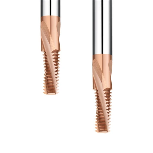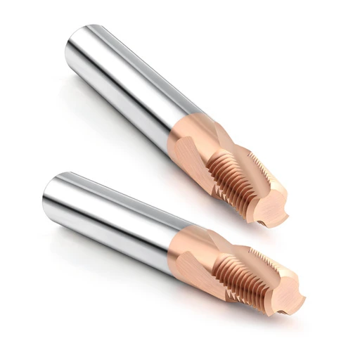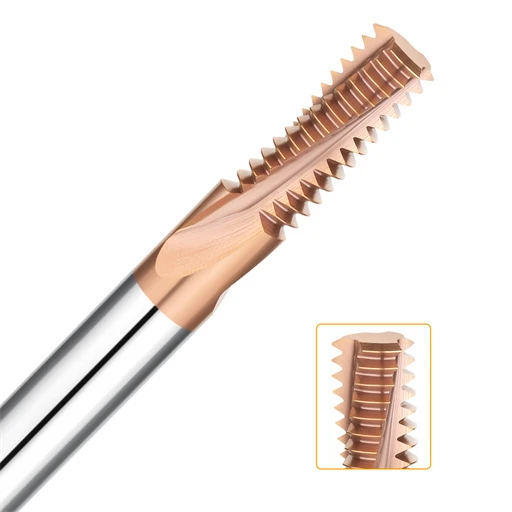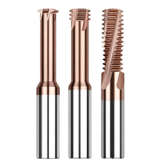

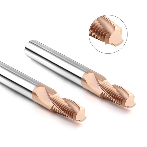
Last month, a German mold-making client emailed us photos of two broken solid carbide thread mills snapped inside blind holes, along with a scrapped powder-metallurgy die insert. The workpiece was vacuum heat-treated cold-work steel hardened to a punishing HRC65. The shop ran standard catalog speeds and feeds. The tool micro-chipped on pass one and sheared off completely on pass two.
Over 16 years of manufacturing cutting tools and troubleshooting shop floors across Europe and North America, we see this failure constantly. Standard cutting rules collapse above HRC60. Machining shifts from clean chip shearing into high-pressure friction and micro-cleaving. When treating ultra-hard steels, catalog charts and default CAM cycles are recipes for broken tools.
Success at 65 Rockwell comes down to dialed-in cutting dynamics rather than coating thickness alone. You must master internal circular interpolation feed compensation, tightly regulated feed per tooth (fz), and a rigid machining setup. If you are staring at scrap parts worth thousands of euros, ask yourself: did the coating burn from high surface speed, or was your programmed feed rate wrong from sentence one?
Tackling Hardened Steel: Why Do Standard CNC Thread Milling Parameters Inevitably Lead to Chipped Edges at HRC65?
Plugging catalog presets or default CAM numbers into an HRC65 setup is an immediate countdown to a snapped tool. Many machinists try simply dialing back spindle speed and flooding the cavity with coolant. At this hardness level, that approach leaves zero margin for error. The substrate’s yield strength easily exceeds the structural limit of standard cutting edges.
Standard CNC thread milling parameters are built around ductile shearing physics, not ultra-hard metals. At HRC65, the cutting edge does not see a smooth, progressive chip load; it endures severe, high-frequency impact cycles. That violent mechanical hammering, combined with extreme localized friction heat, causes rapid edge breakdown and catastrophic chipping.
A Common Pitfall for Western Clients: Neglecting Tool Runout and Machine Rigidity, Leading to Overloading and Micro-chipping of Individual Cutting Edges
When we troubleshoot field setups in North America and Germany, our first step is putting a dial indicator on the tool tip to check runout. Far too many shops run five-year-old standard BT40 ER collets with total radial runout exceeding 0.015 mm (0.0006″). While aluminum or mild steel tolerates that runout, in extreme hardness it is fatal.
Actual chip load per tooth in these operations is often only 0.005 to 0.008 mm. If your tool runout measures 0.010 mm, one single flute takes nearly the entire cutting load. Most complaints about defective tools or unexplained tip fractures actually stem from poor holder runout, which instantly overloads a single tooth and triggers a multi-tooth failure.
The Drastic Difference in Flexural Strength Requirements—Thread Milling SKD11 (HRC 60–62) vs Workpieces Hardened to HRC 65+
Operators often ask us why thread milling SKD11 at HRC60–62 runs smoothly, while switching to an HRC65 punch die destroys the cutter. The answer lies in the dramatic drop in material fracture toughness (KIC). At HRC60, SKD11 still retains enough matrix ductility to form controllable, semi-continuous chips under standard load.
Once deep cryogenic or high-temp tempering pushes a die steel to HRC65, plastic deformation drops to almost zero. You are no longer cutting metal fibers; you are crushing ultra-hard primary carbides. Under a shop microscope, HRC60 wear shows normal flank abrasion, whereas HRC65 produces extensive micro-fractures along the cutting line from unbuffered mechanical shock.
Substrate and Coating Selection for Carbide Thread Mills in Hard Milling: The Threshold for Impact Resistance Using Ultra-Fine-Grained Carbide and AlTiN/TiAlSiN Composite Coatings
Selecting tools for extreme hardness requires balancing wear resistance with impact toughness. Many buyers mistakenly choose the hardest, most brittle tungsten carbide grades available. For our dedicated carbide thread mills running in HRC65, we select an ultra-fine 0.2–0.4 μm grain structure, but we lock cobalt content at 10%–12% to preserve crucial transverse rupture strength.
For coatings, standard monolayer AlTiN breaks down rapidly under 900°C dry friction heat. We apply silicon-doped nanocomposite coatings, such as TiAlSiN or AlCrSiN, rated above HV3600. The added silicon builds an amorphous SiO₂ barrier layer during cutting, blocking heat transfer into the substrate and preserving red hardness so the sharp edge resists deformation.
How to Calculate Thread Milling Parameters: Core Formulas and Practical Compensation Rules
Shop machinists often ask why stable cutting data from turning or face milling destroys thread mills within half a hole. Thread milling is a simultaneous three-axis helical interpolation process. It introduces geometric distortions across instantaneous engagement angles, chip clearance, and contour radii. Without accounting for these mechanics, tweaking speeds and feeds becomes pure guesswork.
Mastering how to calculate thread milling parameters requires balancing surface speed, chip load, and interpolation path geometry. When machining extreme hardness, small calculation errors create severe deflection forces. Even a five-micron feed discrepancy can spike cutting pressure past the tool’s shear limit, causing immediate fracture.
Calculating Basic Cutting Speed and Spindle Speed: Determining Effective Cutting Speed (Vc) and Spindle Speed (S) for HRC65 Thread Milling
When setting line speed for HRC65 steel, cut standard pre-hardened values in half. Our baseline window runs between 25 and 45 m/min. If your machining center features exceptional dynamic balance and minimal overhang, you can test 50 m/min. For older machines with minor spindle vibration, staying around 20 to 25 m/min provides a safer threshold.
Use the standard equation S = (1000·Vc)/(π·D) to convert surface speed into spindle RPM. For a 4.5 mm cutter cutting an M6 thread at 35 m/min, the spindle speed lands near 2476 RPM. When setting HRC65 thread mill cutting parameters, avoid chasing high surface footage. Excessive RPM overheats the tool edge, rapidly stripping the protective coating.
The Fatal Flaw in Thread Milling: Why Feed Rate at the Workpiece Contour (Ff) Must Never Be Used as Tool Center Feed (Fc)
In 70% of our shop-floor breakage investigations, the root cause is this specific feed error. Programmers calculate contour feed rate Ff at the cutting edge and paste that value directly into G02/G03 blocks. However, CNC controllers execute motion commands along the tool’s central axis, not at the cutting perimeter.
During internal helical interpolation, the tool tip sweeps a large circle along the hole wall while the centerline follows a smaller orbit. Applying contour feed $F_f$ directly to the spindle axis forces the tool tip to travel much faster than programmed. This geometric multiplication spikes chip load exponentially, snapping small-diameter cutters the instant they touch the wall.
Tool Center Feed Correction Formula: Derivation of the Circular Interpolation Compensation Algorithm for Internal and External Threads
To prevent edge failure, apply tool-center feed compensation in your post-processor or manual code. For internal threads, centerline path diameter equals nominal major diameter D_major minus cutter diameter D_tool. Calculate your required controller feed rate using:
For external threads, the cutter center travels on a larger diameter than the workpiece, changing the minus sign to a plus sign. In internal operations, corrected center feed Fc is typically only 25% to 40% of cutting-edge feed. Always verify whether your G-code $F$ value targets the profile or the tool centerline before cycling the spindle.
The Critical Window for Feed per Tooth (fz): Excessive Friction Causes Work-Hardening, While Excessive Feed Causes Tool Breakage
Setting the chip load on 65 Rockwell steel demands tight tolerance. The operating window for thread milling feed per tooth is narrow, sitting between 0.004 mm and 0.012 mm per tooth. If hole depth exceeds twice the tool diameter, start initial passes at 0.005 mm/tooth. Prioritize process stability and tool life over raw cycle time.
Never drop the feed rate too low in a misguided bid for safety. Dropping below 0.003 mm/tooth falls below the hone radius of the carbide cutting edge. The tool rubs instead of shearing, work-hardening the workpiece surface. That friction overheats the flank face and chips subsequent teeth on the very next revolution.
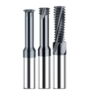
Thread Mill Parameters for Hardened Steel: Multi-Pass Incremental Feeding and Toolpath Design
Attempting to cut full thread depth in a single pass on HRC65 stock guarantees broken tooling. High cutting resistance induces immediate elastic deflection and brittle fracture in small-diameter shanks. Producing clean, in-spec 6H threads requires dynamic toolpaths that account for chip evacuation, radial forces, and spindle rigidity.
When tailoring thread mill parameters for hardened steel, your main objective is relieving cutting stress. Distribute tool load across graduated radial passes and use smooth tangential lead-ins to protect cutting tips. Strategic path planning prevents tool breakage, eliminates dwell witness marks, and controls thread taper across the entire bore.
The “Golden Decremental” Strategy for Radial Depth of Cut (ap): Allocating Stock from Roughing to Final Finishing Passes
Never divide radial depth of cut into equal increments on hardened steel. Splitting a 0.6 mm depth into three 0.2 mm passes overloads the cutter on pass three. As radial depth increases, the cutter contact arc widens, expanding tool engagement area. Equal step-overs cause cutting forces and friction to spiral out of control during final cuts.
We rely on a strict decremental step-over schedule across three to four passes. Pass one removes 50% to 60% of radial stock, pass two takes 25% to 30%, and pass three finishes the profile with the remaining 10% to 15%. For deep holes, add a final spring pass along the same toolpath with zero radial offset to clean up tool deflection.
Climb Milling and Entry/Exit Paths: How 180° Arc Approaches Eliminate Tool Marks and Impact Shocks
Climb milling is mandatory on HRC65 steel, provided your machine axes lack mechanical backlash. Conventional milling forces the tooth to engage at zero chip thickness, sliding against the work-hardened surface before cutting. Climb milling enters at maximum chip thickness, directing cutting forces into the machine structure and eliminating vibration.
Avoid linear 90° radial moves straight into the hole wall. Sudden perpendicular engagement shocks the brittle carbide edge, causing micro-chipping and chatter lines. Always program a smooth 180° semi-circular or 90° tangential arc for entry and exit. This ramps tool load progressively to its peak, ensuring pristine thread flank finishes.
Cutting Resistance Considerations: Single-Tooth vs. Full-Profile Tools in Deep, Hardened Bores
Full-profile thread mills finish threads in a single 360° revolution, but their use is strictly limited by hole geometry. While efficient in shallow holes under 1.5 times the diameter, their broad contact area generates severe radial forces. In deep holes or large thread pitches, multi-tooth cutting pressure quickly exceeds the fracture limit of carbide shanks.
For deep bores in HRC65 steel, switch to single-tooth or three-tooth thread mills. While a single-tooth tool requires multiple helical revolutions and longer runtimes, it limits cutting contact to a single point. This reduces radial deflection forces by over 80%. In extreme hardness, eliminating broken tools and scrap parts is the fastest way to cut costs.

Practical Case Study: Deriving Thread Milling Speeds and Feeds for M6×1.0 Internal Threads in HRC65 Hardened Die Steel
Formulas mean nothing if they fail at the machine control. In precision automotive stamping dies, M6×1.0 threads are common and notorious for broken tools. These plates are vacuum-hardened to HRC65 with depths reaching 10 to 12 mm. Ignoring spindle dynamics on blind holes will scrap high-value tooling blocks.
We established a proven derivation process in our test center while supporting prototyping across North America and Europe. Below is a real-world setup covering holder rigidity, radial compensation, and final execution. Follow these exact steps to lock in reliable thread milling speeds and feeds before cycling the start button.
Initial Parameter Input and Machine Tool Condition Verification: Standard Configuration with BT40/HSK63 Spindles and Shrink-Fit Tool Holders
Machine mechanical condition dictates your baseline. For HRC65 die steel, use a direct-drive BT40 (dual-contact BBT preferred) or an HSK-A63 spindle. Geared heads exhibit backlash that triggers chatter during micro-step interpolation. If you must run a standard BT40 taper, keep dynamic radial runout under 0.003 mm.
Toolholders allow zero compromise. Never run standard ER collet chucks. We specify shrink-fit or high-precision hydraulic holders. For an M6 thread, select a 4.5 mm diameter solid carbide thread mill with three flutes (z = 3) and overhang under 18 mm. Total runout at the tool tip must stay below 0.005 mm to prevent tooth overload.
Practical Calculation Exercise: Determining Everything from Cutting Speed and Feed per Tooth to the Machine’s Interpolated Feed Rate (F)
Let us calculate a live cut. In HRC65 stock, we set surface speed conservatively at Vc = 35 m/min. Using our 4.5 mm cutter (D_tool), we calculate spindle speed:
We round this to an even S = 2500 rpm at the console.
Next comes the feed calculation. We start initial passes with a conservative chip load of fz = 0.006 mm/tooth. Nominal peripheral feed along the workpiece contour is:
Entering 45 mm/min into G02/G03 blocks will instantly snap the tool. Because the tool centerline travels a much tighter radius inside an M6 internal thread (D = 6.0 mm), apply centerline feed compensation:
Your programmed CNC feed rate is F = 11.25 mm/min—exactly 25% of the nominal cutting rate.
Cold Air vs. Minimum Quantity Lubrication (MQL): Why Is Flood Cooling with Water-Soluble Coolant Strictly Prohibited When Tapping High-Hardness Steel?
When operators see glowing chips, they instinctively flood the bore with coolant. On HRC65 steel, flood emulsion causes immediate catastrophic edge failure. Tip temperatures exceed 800°C in the cut, then drop violently when submerged. This thermal shock creates microscopic cracks perpendicular to the cutting edge, shattering carbide within three revolutions.
We mandate dry machining with a high-pressure cold-air blast (0.6+ MPa) aimed straight into the bore. The goal is chip evacuation rather than chilling the tool. Recutting trapped, hardened chips destroys delicate teeth instantly. For extreme finishes, add a light MQL vegetable mist, but never drown the cutter.
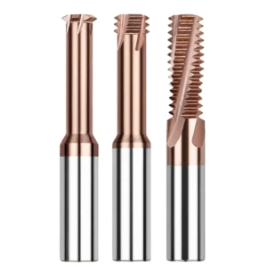
HRC65 Thread Mill Machining Guide: Troubleshooting Tool Breakage and Thread Plug Gauge Failures
Even with accurate speeds, feeds, and toolpaths, shop-floor variables still occur. Machining 65 Rockwell steel tests machine geometry, clamping rigidity, tool wear, and internal stock stresses. A variance of five microns can cause a stuck thread gauge or a broken shank.
We treat setup adjustments as a closed-loop engineering process. Based on hundreds of customer audits, we compiled this practical HRC65 thread mill machining guide. If you run into issues on the floor, use these three diagnostic steps to isolate and correct the root cause immediately.
Tapered Threads (Larger at the Top, Smaller at the Bottom) and Pitch Diameter Deviations: Addressing Tool Deflection and Implementing Bi-Directional Toolpaths
In deep holes, threads often gauge correctly at the mouth but bind halfway down. This taper rarely comes from machine axis pitch errors. It results from radial tool deflection. Under heavy cutting pressure in HRC65 stock, the small-diameter carbide shank bends inward, reducing the effective cutting radius near the bottom of the bore.
If you face taper errors, shorten tool overhang by 1 to 2 mm first. If clearance prevents that, add taper compensation in your CAM program or use bi-directional toolpaths. Rough from the bottom upward, then finish with a top-down climb pass. You can also run a zero-depth spring pass at the floor to clear elastic deflection.
Analyzing Whitening, Tearing, or Chipping on Thread Surfaces: Identifying Micro-Wear Characteristics Linked to Low Feed Rates and Coating Delamination
If thread flanks look hazy or white under inspection, do not change the tool blindly. A burnished, milky finish points to an excessively low feed per tooth. The chip load is smaller than the edge hone radius, rubbing and work-hardening the steel. Tearing at the thread root indicates poor chip evacuation and recutting.
If you inspect the cutter under a loupe, look at the wear land. Smooth abrasive flank wear means balanced feeds and speeds. If the coating is flaking away from the carbide substrate, your cutting zone is overheating. Raise cold air pressure immediately or drop surface speed by 10% to preserve the nanocomposite coating.
Troubleshooting Thread Plug Gauge Issues: Compensating for Wear-Induced Deviations and Addressing Backlash
A frustrating scenario happens when the “NO-GO” gauge enters a turn or two while the “GO” gauge binds. This occurs when machine backlash turns the circular toolpath into an ellipse, or when flank wear deforms the thread crest. The “GO” gauge binds on the narrow axis, while the “NO-GO” gauge catches the wide axis.
If you encounter this gauge mismatch, adjust radial wear offset in 0.005 mm decrements. If the “NO-GO” gauge still enters, check your X and Y axis ball-screw backlash immediately. Programming an extra 15° to 30° tangential overlap arc at entry and exit also eliminates quadrant transition dwell marks.
Heat-treat quality, carbide distribution, and spindle rigidity vary across every shop floor. If you are struggling with a deep blind hole or failing thread gauge inspection on hardened die steel, share your hole depth, tool specs, and post-heat-treat hardness with us so we can review the cutting mechanics together.