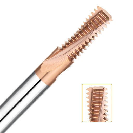

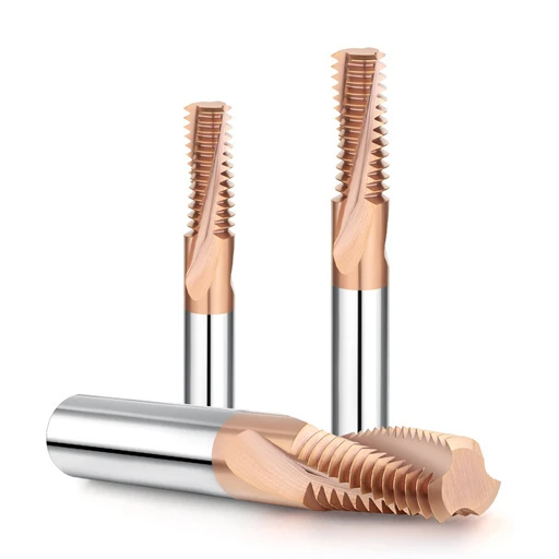
Late last year, we were called to troubleshoot a tooling crisis at a German precision mold shop. The team was threading a powder-metallurgy steel insert hardened to HRC 64–65.5. The part had already undergone dozens of hours of EDM, finish milling, and vacuum heat treatment.
A shop floor technician attempted to tap an 18 mm deep blind hole with a standard rigid tap. On the second thread, the tool snapped flush inside the cavity. The entire workpiece—worth thousands of euros—was suddenly facing scrap, halting an entire production shift.
In our 16 years of solving machining bottlenecks for European and American die makers, we encounter this scenario constantly. Above HRC 60, mold steels lose virtually all plastic ductility. Tapping creates excessive torque, chip packing, and spindle lag, making brittle tool failure inevitable.
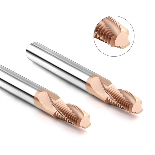
That is why we consistently guide precision mold builders toward a dedicated HRC65 thread milling strategy.
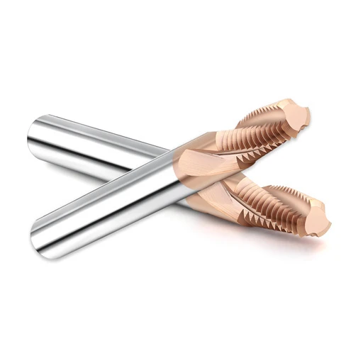
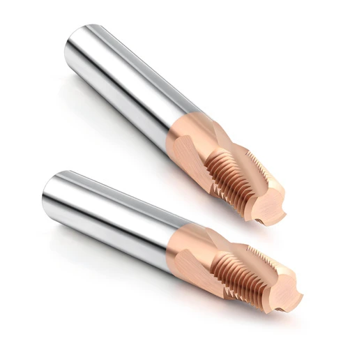
Unlike rigid taps, a solid carbide thread mill uses helical interpolation to convert brutal cutting forces into controlled, localized shear loads. Still, success requires far more than posting standard G02/G03 code:
-
Rigidity vs Runout: Over a 3D overhang, minor runout spikes cyclic fatigue stresses. We strictly enforce a total runout ceiling of 0.003 mm at the tool tip.
-
Radial Multi-Pass Logic: When applying an internal thread milling strategy or deep hole thread milling strategy, single-pass full engagement guarantees severe tool push-off. Incremental radial passes are mandatory.
-
Thermodynamic Management: Flood coolant triggers thermal cracking on carbide teeth. Stable tool life requires fine-tuned cutting speeds paired with high-pressure air blast or minimum quantity lubrication (MQL).
When an expensive, hard-milled mold core sits on your 5-axis machine, are you willing to risk the entire cavity on a rigid tap—or are you ready to adopt a proven thread milling process that guarantees zero taper?
The Cornerstone of Thread Milling in Hardened Steel: Selecting Solid Carbide Thread Mills and Designing for Chipping Resistance
When raw workpiece hardness crosses HRC 60, operators often blame machine rigidity or cutting speed for premature failure. Across dozens of technical support cases, we found that over 70% of early-stage edge chipping comes from selecting a solid carbide thread mill using standard-steel rules. At HRC 65, the tool performs high-frequency micro-shearing under severe friction, where minor stress points immediately trigger micro-chipping.
We evaluate tooling based on structural deflection resistance under lateral cutting loads, not speed records. Factors like carbide grain fracture toughness, edge hone micro-geometry, and tooth cross-sections must be balanced against abrasive wear. If you are preparing to thread hardened mold cores, start by scrutinizing your tool overhang and flute structure.
Opt for Short-Flute, Multi-Flute Solid Carbide Thread Mills for HRC65 Mold Steel to Prevent Tool Deflection
We once assisted a stamping die plant where HRC 64 powder-metal inserts consistently failed go/no-go gauge checks. The threads were loose at the top and tight at the bottom. We found they were cutting the full thread in one pass using a general-purpose, 3D flute-length tool. That massive radial engagement pushed the slender tool off-center, cutting a pronounced taper.
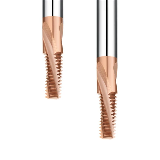
For these hard alloys, our standard rule specifies a short-flute (1D to 1.5D) solid carbide thread mill with neck relief. A 4-flute or 6-flute design distributes cutting loads and maintains practical metal removal rates at a very small chip load. Crucially, the short flutes provide maximum cross-sectional rigidity, eliminating deflection at the source.
Matching Ultra-Fine-Grain Carbide Substrates with High-Heat-Resistance Coatings for High-Hardness Thread Milling
Machinists often ask us if sub-micron carbide grain size is always superior for hard steel. In our tool grinding operations, selecting the right thread mill cutter requires a calculated trade-off. We maintain tungsten carbide grain sizes at 0.2 to 0.4 µm with 8% to 10% cobalt. Too little cobalt invites brittle fracture, while too much cobalt degrades high-temperature hardness.
Coating chemistry is just as critical, and we have phased out standard TiAlN. Shear-zone contact temperatures routinely exceed 900°C, causing conventional films to peel. We rely on nanocomposite TiAlSiN or AlCrN coatings. Under dry air blast, they form an amorphous passivation layer resisting oxidation up to 1100°C while dropping friction below 0.35.
Toolholder Rigidity Control: The 0.003mm Runout Limit for Shrink-Fit and Hydraulic Chucks in Thread Milling Hardened Steel
In premier mold shops, you will rarely find standard ER collet chucks used for thread milling hardened steel. During tool failure analyses, we routinely see two flutes worn out while the remaining two stay pristine. The culprit is dynamic runout. At very light feed-per-tooth settings, a mere 0.008 mm runout doubles the workload on a single flute, triggering rapid chipping.
Our shop standard caps total indicated runout (TIR) at 0.003 mm (3 microns) at the cutting teeth. We enforce shrink-fit holders or high-rigidity hydraulic chucks with short tool stick-out. Shrink-fit chucks offer near-perfect concentricity and superior clamping force, ensuring balanced tooth loading during helical cuts. Retiring worn collet chucks eliminates most recurring tooling expenses.
The Underlying Logic of Cutting Parameters: Optimizing Cutting Speed and Feed for Thread Milling Hardened Steel
Machining HRC65 mold steel leaves zero margin for trial and error. Internal thread milling involves tight helical interpolation where the tool-to-bore contact arc is much larger than in face milling. If you run general hardened steel milling parameters here, friction spikes instantly. The resulting cut resistance triggers severe chatter, ruining an expensive, finished die component within seconds.
Our thread milling strategy for hardened steel prioritizes thermal stability and chip formation over raw cycle time. We do not chase high metal removal rates on HRC65 parts. Instead, we lock in precise cutting speeds, light tooth loads, and exact arc feed conversions so each flute shears smoothly without generating a work-hardened white layer.
Precisely Setting Cutting Speed (Vc) and Feed per Tooth (fz) to Prevent Thermal Wear and Micro-chipping
We recently diagnosed a Swiss connector mold shop where an operator ran an HRC65 punch retainer at 80 m/min. Both M3 cutters burned out and chipped before finishing the second hole. Cold-work steels with tensile strengths over 2200 MPa do not dissipate heat through chips efficiently. Our shop floor tests prove that capping your thread milling cutting speed between 35 and 55 m/min offers the best balance between edge retention and throughput.
Do not make the rookie mistake of dropping your chip load to zero. If your feed per tooth (fz) drops below 0.005 mm/tooth, the tool rubs rather than cuts, dulling edges exponentially fast. We hold fz strictly between 0.008 and 0.02 mm/tooth. This allows the micro-honed edge to penetrate past the shear plane cleanly without generating destructive radial deflection.
Feed Conversion for Internal Thread Milling (Linear Feed vs Circular Feed) and Tool Breakage Prevention
This is the most common programming bug we catch in precision machine shops. Programmers frequently take the CAM-calculated linear feed and paste it directly into the CNC control. Because the tool centerline travels a much tighter radius than the outer cutting edge, the true chip load surges. Without internal circular feed compensation, an intended 0.015 mm tooth load can spike past 0.04 mm, snapping the cutter instantly.
To protect your cutter, you must enforce a mathematical conversion between linear feed vs circular feed. Use the classic ratio: Centerline Feed = Outer Edge Feed × (D – d) / D, where D is the nominal thread diameter and d is the cutter diameter. For an M6 thread cut with a 4.5 mm mill, the programmed centerline feed must be dialed down to ~25% of the theoretical feed.
Engineering Choices for Coolants: High-Pressure Air Cooling, MQL, and the Prohibition of Liquid Coolants
Some machinists flood the tool with coolant the moment they see cutting heat. In HRC65 blind-hole threading, flood coolant is fatal to carbide flutes. Thread milling is an interrupted cut. When hot carbide teeth rotate between blazing shear zones and cold liquid, severe thermal shock occurs. Comb-like micro-cracks form across the cutting edge within seconds, leading to catastrophic spalling.
We strictly ban liquid coolant when thread milling hardened steel. Run dry with filtered air at 6 bar minimum, or use a MQL system. High-pressure air blasts hot, hardened chips out of the hole, stopping recutting dead in its tracks. Adding a light vegetable-ester oil mist forms a robust boundary film, slashing friction without triggering thermal micro-fractures.
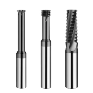
Tackling Blind and Deep Holes: Practical Strategies for Internal and Deep-Hole Thread Milling
Threading deep inside a near-finished mold cavity tests any machinist’s nerve. Deep holes combine long tool overhangs, blind chip packing, and zero line of sight. One resonant chatter frequency or pinched chip can gouge hardened sidewalls beyond repair. Over 80% of the tool failures we troubleshoot happen at the bottom of deep blind pockets under abnormal cutting forces.
Our internal thread milling strategy treats deep features as distinct dynamic systems rather than extended shallow holes. Success comes down to three physical controls: dampening tool deflection, programming smooth entry paths, and providing adequate chip evacuation relief. Distribute your lateral cutting pressures across stable helical passes, and the risk vanishes.
Deep-Hole Thread Milling Strategy for Mold Cavities: A Radial Multi-pass Approach
A North American die-cast shop recently asked us why their tools snapped while cutting 22 mm deep M6 threads in H13 inserts (HRC 63–65). The programmer took the full thread depth in a single radial pass to save time. Two-thirds down, lateral load caused elastic bending, chattering violently and shearing the flutes. Single-pass threading at high depth-to-diameter ratios guarantees extreme taper and broken tools.
Our proven deep hole thread milling strategy relies on radial multi-pass stepovers. For HRC65 stock, split the radial thread depth into three or four passes: 55% roughing, 30% semi-finishing, 15% final profiling, and an unloaded spring pass. This progressive approach eliminates tool push-off and guarantees true cylindrical pitch diameters from the mouth to the floor of the bore.
Entry and Exit Path Design for Internal Thread Milling: Using 90° Arcs to Avoid Instantaneous Impact
Never plunge your thread mill straight into a hardened bore along a perpendicular vector. Soft steels can absorb that initial slap, but HRC65 tool steel cannot. Dynamometer testing shows perpendicular plunge forces spike over three times higher than steady-state helical cutting loads. That initial shock wave easily chips sharp crests on new carbide teeth.
Under our standard internal thread milling strategy, you must program a 90° tangential roll-in and roll-out arc. Synchronize the radial entry arc with an axial Z-lift matched to your thread pitch. The cutter feathers into the cut from zero chip thickness, sweeps the 360° helix, and rolls out smoothly. This eliminates entry shock and leaves seamless thread walls with zero witness dwell marks.
Chip Evacuation in Blind Holes and Residual Stress Control: Prioritizing Climb Milling and Increasing Pilot Hole Tolerances
In deep blind holes, chip clearance dictates tool survival. Always climb mill bottom-up, starting at the hole base and interpolating upward toward the exit. This pulls hot chips out along the flutes instead of packing them into the bottom. Furthermore, do not blindly drill nominal pilot diameters listed in general machining handbooks.
When thread milling hardened steel, drill your pilot bore toward the upper tolerance limit—typically 0.05 to 0.10 mm larger than standard chart values. For an M6 hole, sizing the pre-drilled bore to 5.10–5.15 mm limits thread height to roughly 70%. This minor change slashes thread-crest tool engagement, creates chip clearance, and eliminates edge chipping caused by recutting packed debris.
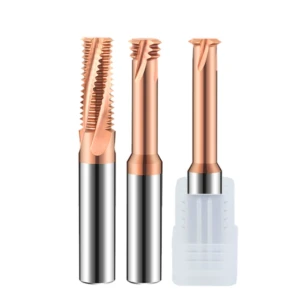
Tackling Small Diameter Holes: Strategies to Prevent Tool Breakage During Thread Milling in Hardened Ejector Pin Holes and Inserts
M2 to M4 threads are common in connector molds and semiconductor inserts. Cutting threads at HRC65 in this micro-range leaves zero room for error. Because tool core diameter drops rapidly, torsional and flexural rigidity plunge cubically. Even a minor spindle-orientation runout or coolant residue resistance will snap a micro-cutter tip instantly.
When implementing small diameter thread milling on hardened mold inserts, abandon the habits used for larger threads. Micro-machining requires managing dynamic tool deflection rather than relying on static stiffness. You must calculate the tool’s elastic bending during motion and control pre-hole geometry upstream so a tool thinner than a wire survives.
Deflection Compensation and Speed Reduction Rules for Small-Diameter Thread Milling with High Overhang Ratios
A Swiss micro-mold shop once broke two consecutive tools cutting M2.5 blind holes in HRC64 powder-metallurgy inserts. To clear cavity sidewalls, they selected a micro-mill with an overhang near 4D. At high depth-to-diameter ratios, minimal lateral cutting load causes severe elastic bending. When the tool lags behind its toolpath and springs back, the tooth face overloads and snaps.
Under our small diameter thread milling rules, two safeguards run simultaneously. First, apply micron-level radial tool offsets in the CNC program, splitting total thread depth into 4 to 5 passes with radial stepover (ae) below 0.015 mm. Second, reduce cutting speed by 20% to 30%, holding it at 25 to 35 m/min. Trading a few extra seconds per hole prevents EDM extraction of snapped micro-tools.
Eliminating the Work-Hardened Layer in the Pilot Hole: How Prior Carbide Drilling Affects the Lifespan of Small Diameter Thread Mills
When micro-thread mills chip, operators often tweak milling parameters without inspecting the drilled bore. In our failure analyses, premature wear usually traces back to the pre-hole. Drilling HRC65 tool steel with a slightly worn carbide drill generates high frictional heat, forming a work-hardened white layer on the bore wall that is harder than the base metal.
When a solid carbide thread mill enters the hole, its delicate cutting edge strikes this brittle white layer on the first pass, causing rapid abrasive dulling. We require pre-hole drilling to be monitored as strictly as the threading pass itself. Keep drilling feeds controlled to prevent work-hardening, or ream the hole prior to threading to ensure uniform material structure.
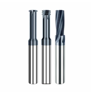
On-Site Troubleshooting: Common Pitfalls in Western Mold-Making Shops and a Checklist for Optimizing Thread Milling Strategies
In our technical support visits across European and American mold shops, success rarely depends on machine price. It depends on disciplined troubleshooting logic. At HRC65, high material yield strength magnifies every minor setup flaw. Tool runout, overhang deflection, arc feed conversion, air blasts, and radial passes must work in unison to protect tool life.
Our thread milling strategy checklist uses a closed-loop diagnostic framework. When cutting anomalies appear, avoid making random parameter tweaks at the controller. Separate machine dynamics, holder rigidity, and cutting geometry into isolated checks. Using measurable physical metrics to isolate the root cause is the fastest way to protect expensive hardened inserts.
Troubleshooting and Tool-Offset Correction for Thread Gauge Failures and Taper Deviations
Shop inspectors frequently report that a no-go gauge clears while a go gauge binds halfway down the bore. If you face internal thread taper or pitch distortion, follow our three-step audit: check spindle and tool-tip runout with an indicator, confirm that arc feed compensation is active in CAM, and verify that radial passes distribute cutting loads evenly.
If you are fighting taper in deep blind holes over 2.5D, program an unloaded spring pass with a slight axial taper tool offset. If thread crest friction remains high, enlarge pilot bore diameters by 0.05 mm toward the upper limit. Adopting an internal thread milling strategy that uses progressive radial passes will absorb deflection and ensure your threads consistently pass gauge inspection.
Deducing Cutting Parameters and Toolpaths from the Metallographic Morphology of Tool Wear
Worn tool edges provide direct insight into cut mechanics. We have examined hundreds of dulled cutting edges under toolmaker microscopes. A uniform silver-gray wear band on the relief face indicates that surface speed and lubrication are dialed in. If you observe comb-like thermal cracks or tooth flaking, liquid coolant thermal shock or weak air blast is the issue.
Similarly, corner chipping on the first tooth points to an abrupt, linear plunge into the bore wall; fix it immediately with a 90° tangential roll-in arc. If you are cutting tough grades like Caldie, CarMo, or high-vanadium powder steels with aggressive depth-to-diameter ratios, send over your part drawings, hole depths, and machine specs. We are always glad to review cut data and help dial in your setup.