


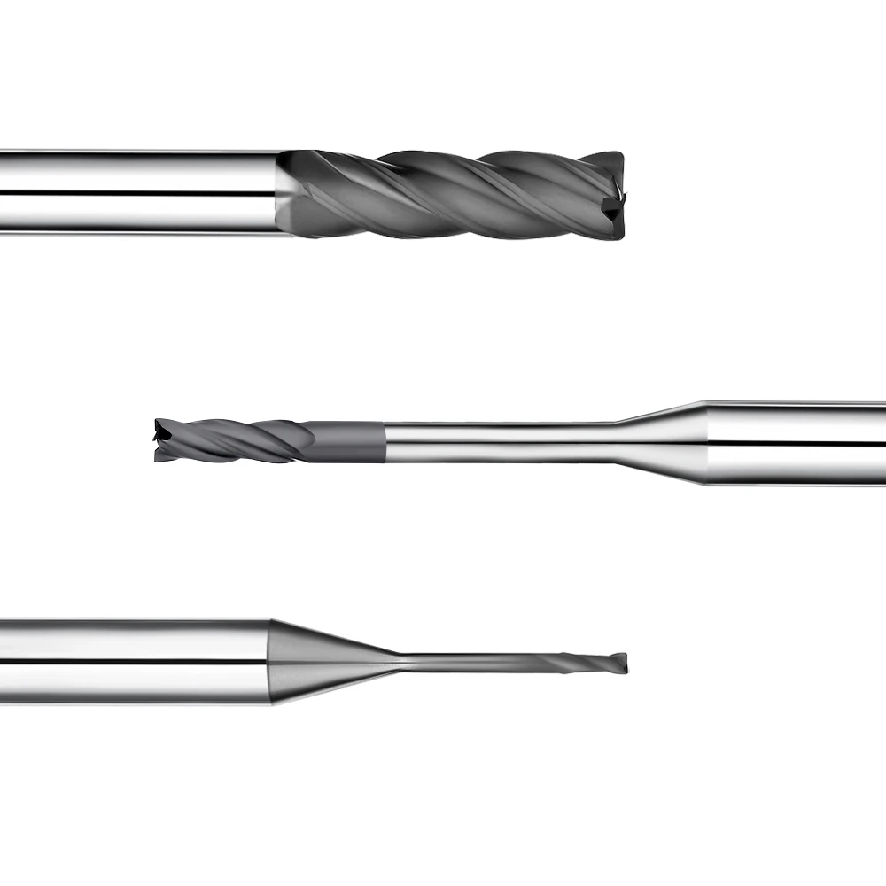
During a recent graphite electrode machining project, a client faced an unexpected challenge. Using the same batch of graphite and the same CNC machining center, the surface finish was perfect initially. However, after continuous milling, the electrode surfaces developed severe tool marks, micro-chipping, and increased surface roughness. Although the client suspected material inconsistencies, our engineering analysis pointed to tool wear, parameter imbalances, and process misalignment.
We frequently encounter similar issues across high-precision graphite projects. This is especially true for custom EDM electrodes and graphite molds, where surface finish directly impacts EDM performance. When milled graphite surfaces show visible marks or fluctuating Ra values, it means your process is out of balance.
Graphite is an inherently brittle, granular material with a micro-layered structure. Because of these unique physical properties, graphite milling is extremely sensitive to cutting forces, edge sharpness, and chip evacuation. Incorrect cutting parameters—such as improper spindle speed or high feed rates—accelerate tool wear and instantly degrade surface quality.
To solve roughness issues, engineers must evaluate the entire CNC machining system. This includes spindle runout, machine rigidity, tool selection, dust collection, and toolpath strategies. Simply swapping a worn tool for a new graphite end mill rarely solves the root cause if system vibration or parameters remain unoptimized.
Achieving a consistently smooth surface finish requires a holistic graphite machining strategy. Every detail matters, from selecting the right graphite grade to optimizing tool geometry and feed rates. Through years of hands-on experience, we have learned that process control is just as vital as tool quality.
In this article, we analyze why graphite surfaces degrade during production runs based on real customer cases. We will explore material behavior, tool wear mechanisms, parameter optimization, and system rigidity. As a professional graphite tool manufacturer, we also share practical solutions to help you achieve stable, high-precision surface finishes.
So, why do your graphite parts start with a flawless finish, only to grow increasingly rough over time? Let us uncover the root causes and practical solutions below.
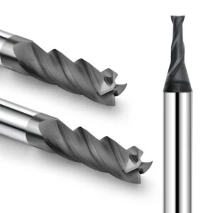
Graphite Surface Roughness Analysis: Why Does Surface Quality Deteriorate After CNC Graphite Milling?
In precision graphite machining, graphite surface roughness remains a primary quality concern for engineering teams. Even when dimensional tolerances are met, post-milling defects like tool marks, micro-chipping, and surface dullness can severely degrade EDM performance. Based on our shop-floor experience, these quality issues rarely result from a single parameter, but rather from the complex interaction between material response, cutter condition, and process dynamics.
Diagnosing a sudden drop in milling quality requires analyzing material grades, toolpaths, and real-time cutting states together. Achieving a pristine surface finish on high-precision graphite electrodes relies on strict process control, including optimized chip evacuation and light finishing loads. Pinpointing the exact root cause of surface roughness is the only way to apply lasting solutions to your production line.
How Do Graphite Material Properties Affect Surface Roughness?
Machining results vary significantly across different graphite grades, even under identical CNC setups. These variations stem directly from particle grain size, bulk density, and internal binder strength. Fine-grained, high-density graphite consistently yields smooth surfaces, whereas coarse-grained materials are prone to micro-fracturing and high surface roughness during aggressive milling.
In one client project, machining precision electrodes with standard-grade graphite created severe surface roughness that high spindle speeds could not fix. Quality improved drastically only after switching to a fine-grained graphite grade and optimizing the finishing allowance. Selecting the correct material grade is always the foundational step toward achieving superior surface finishes.
How Does Graphite Particle Structure Lead to Surface Defects During Milling?
Unlike ductile metals, graphite undergoes brittle fracture and micro-spalling during high-speed CNC milling. When inspect tool-engaging surfaces under magnification, localized pitting and particle pull-out are commonly observed. These surface defects directly correlate with the material’s granular structure and how cutting forces act upon the brittle matrix.
As tool edges dull, elevated cutting forces break the bonds between graphite grains rather than shearing them smoothly. This structural damage becomes especially visible during thin-wall finishing or intricate cavity milling. Prioritizing razor-sharp tool edges and light cutting loads is essential to prevent grain breakout on delicate features.
How Do Machining Vibrations and Tool Wear Compromise Graphite Surface Finish?
Extensive production data shows that deteriorating surface finish is frequently caused by progressive tool wear and dynamic vibration. A sharp graphite milling cutter performs exceptionally well initially, but slight flank wear alters cutting geometry. This subtle change increases tool pressure, resulting in heavy tool marks and rough surface patches on finished parts.
To prevent surface degradation, engineers must continuously monitor spindle runout, toolholder rigidity, and cutter wear patterns. Maintaining a uniform surface finish requires a balanced synergy between machine tool stability and optimal cutting parameters. Neglecting system chatter or tool degradation will inevitably lead to erratic surface roughness over long production runs.
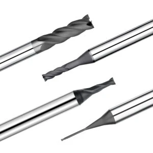
Graphite Machining Process Analysis: Key Factors Causing Surface Roughness
In precision graphite component production, unexpected surface roughness can often be traced back to weaknesses in process planning. Machinists often focus on dimensional accuracy while overlooking dynamic cutting conditions, such as uneven stock allowances and improper toolpaths. For brittle materials like graphite, maintaining process stability is far more critical than simply pushing high feed rates.
Evaluating surface defects requires analyzing the entire graphite machining process rather than isolated cutting parameters. Engineers must review the machining logic, toolpath continuity, allowance distribution, and dust extraction efficiency simultaneously. Poor surface quality is rarely caused by a single pass, but rather by accumulated instabilities throughout the machining cycle.
How Do Improper Graphite Milling Parameters Increase Surface Roughness?
Increasing feed rates or depths of cut to reduce cycle time often backfires by introducing heavy chatter marks and edge chipping. In one customer shop, high tool loads exceeded stable cutting limits, destroying the finish on high-density electrodes. Overly aggressive parameter settings generate severe mechanical impacts that fracture fragile graphite particles instead of shearing them smoothly.
Optimizing graphite milling parameters requires balancing material density, tool diameter, step-over distance, and target surface finish. During finishing passes, operators should reduce cutting forces to stabilize the cutter edge rather than repeating roughing values. Combining proper spindle speeds, feed rates, and light cut depths consistently yields superior surface quality.
How Do Cutting Speed and Feed Parameters Affect Graphite Machining Quality?
Achieving optimal graphite machining quality depends on maintaining a balanced ratio between cutting speed and feed per tooth. High spindle speeds alone will not guarantee a smooth finish if feed rates cause tool rubbing or discontinuous cutting. Improper speed-to-feed synchronization generates visible vibration patterns across finished electrode surfaces.
Machinists should adjust cutting parameters dynamically based on tool overhang, flute count, and graphite grade. When using small-diameter end mills in deep cavities, tool deflection becomes the primary cause of surface flaws. Proper parameter calibration ensures steady chip formation and prevents surface roughness, even under demanding geometric conditions.
How Do Roughing and Finishing Processes Impact Precision Graphite Machining?
Fluctuating surface finish during final passes often stems from uncontrolled stock allowances left by aggressive roughing operations. If roughing leaves excessive or uneven material, the finishing tool encounters changing cutting loads that induce deflection and vibration. This dynamic instability degrades dimensional accuracy and leaves micro-grooves on critical electrode faces.
High-precision graphite machining relies on a structured sequence: roughing, semi-finishing, and final stress-relieving passes. This multi-stage approach normalizes cutting forces and maintains precise allowance control before the final tool engages. Achieving a flawless surface finish requires every step of the machining process to work in harmony.
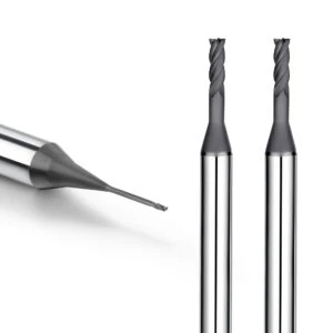
Graphite End Mill Wear: How Does Tool Wear Lead to Rough Surfaces in Graphite Machining?
Tool condition is often the most overlooked factor when investigating degrading surface roughness in graphite production. Shops frequently see perfect finishes on initial parts, only to encounter severe tool marks and micro-chipping after continuous operation. On-site audits show that this degradation rarely stems from machine accuracy loss, but rather from the tool’s inability to maintain a clean shearing action due to edge wear.
Because graphite is an abrasive, brittle material, it demands continuous cutting edge sharpness. As a graphite end mill wears, its dull edge ceases to slice graphite particles cleanly, instead crushing them through high impact forces. This mechanical crushing induces micro-fractures in the material matrix, directly leading to increased surface roughness and compromised workpiece integrity.
How Does Graphite End Mill Edge Chipping Create Machining Marks?
In one electrode machining project, parts met specifications initially, but visible streaking appeared after extended production. Microscopic inspection of the cutter revealed slight edge chipping along the primary flutes. Though invisible to the naked eye, this micro-damage altered the tool’s effective cutting geometry and disrupted the dynamic cutting path.
In precision milling, minor edge chipping does not always cause catastrophic tool failure, but it drastically impacts surface quality. Damaged cutting edges push material unevenly during each revolution, creating micro-grooves and dimensional instability. Identifying cutting edge defects early prevents progressive tool wear from ruining expensive workpieces.
How Do Diamond Coated Graphite End Mills Improve Tool Life?
Standard carbide tools degrade rapidly under continuous machining due to the severe abrasive action of graphite dust. Even minor flank wear—without obvious edge breakage—can ruin delicate surface finishes during final passes. To combat this friction, engineers evaluate edge sharpness, coating adhesion, and chip clearance parameters together.
Using high-performance diamond coated graphite end mills significantly improves wear resistance and minimizes surface finish inconsistencies. However, premium coatings are not a cure-all solution for poor setups. If machine rigidity, spindle runout, or feed parameters are suboptimal, even diamond coated tools will fail prematurely.
How Do You Select the Right Graphite End Mill?
Selecting the optimal graphite end mill requires matching tool geometry to specific machining applications rather than relying on tool diameter alone. Heavy roughing passes require high tool core rigidity and maximum flute space for dust evacuation. Conversely, deep-cavity finishing demands vibration-damping long-reach tools that maintain edge stability under changing loads.
Proper tool selection requires evaluating graphite density, cutting depth, stock allowance, and targeted surface finish. For long production runs, tool longevity alone is insufficient; the cutter must maintain stable geometry over its entire lifespan. Prioritizing cutting stability ensures high-precision results across every batch.
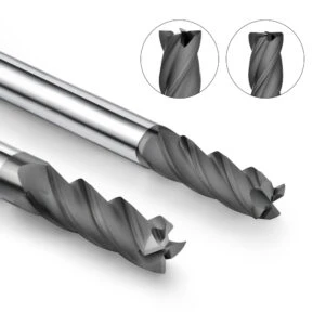
Optimizing the Graphite Machining System: How to Control Surface Quality After Milling?
Surface roughness issues in precision production often stem from holistic system instabilities rather than isolated tooling faults. Shops using identical end mills and materials on different machines frequently report vastly different finishes. On-site technical audits show that machine rigidity, dust extraction, workholding, and parameter alignment all dictate final surface quality.
Achieving high-precision electrodes requires optimizing the entire graphite machining system as an integrated ecosystem. Maintaining a predictable finish demands complete alignment among machine kinematics, cutting tools, parameters, and environmental controls. This systemic harmony eliminates process variations and guarantees consistent, high-quality production results.
How Do CNC Machine Rigidity and Spindle Precision Affect Graphite Surface Finish?
Executing identical programs with identical tools across different machine tools can yield surprisingly varied surface finishes. Diagnostic inspections typically reveal root causes like excessive spindle runout, weak workholding, or structural machine flex. Because brittle graphite reacts poorly to micro-vibrations, minor system instability quickly manifests as severe surface defects.
Spindle accuracy and dynamic machine rigidity directly define the cutter path during milling operations. Insufficient stiffness induces tool chatter, leading to surface waviness and micro-fracturing on finished electrode faces. Evaluating machine tool condition alongside parameter tuning is essential for restoring a superior graphite surface finish.
How Does a Dust Control System Reduce Graphite Machining Defects?
Uncontrolled abrasive dust created during dry milling frequently compromises finished surface quality. In deep-cavity electrode machining, accumulated graphite powder acts as a secondary abrasive within the cutting zone. This re-cutting action dramatically accelerates cutter flank wear and degrades fine surface details over prolonged production runs.
An efficient dust control system is vital for stabilizing the cutting environment and extending tool life. Rapid dust evacuation prevents particle re-cutting, protecting critical workpiece surfaces from abrasive degradation. Practical shop-floor experience proves that upgrading vacuum performance instantly resolves many lingering surface finish defects.
How Does Optimizing Process Parameters Enhance the Performance of a Graphite Machining System?
Replacing worn tools without re-evaluating cutting parameters rarely delivers long-term finish improvements. Process settings must align with graphite density, tool geometry, overhang length, and specific machining stages. Roughing requires prioritizing chip clearance and structural stability, whereas finishing demands minimal edge loads and supreme path smoothness.
Maximizing system performance requires balancing spindle speeds, feed rates, cut depths, step-over values, and toolpaths together. Harmonized process parameters mitigate abnormal mechanical loads and prevent unexpected thermal deformation. Proper process calibration ensures your entire machining setup maintains elite finish standards over extended shifts.
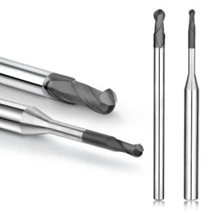
Optimizing Graphite Milling Parameters: Methods to Improve Graphite Surface Roughness
Improper cutting parameters remain a primary cause of high graphite surface roughness in job shops. Operators seeking faster throughput often push feed rates and cutting depths beyond material limits, causing severe edge chipping and particle breakout. Technical evaluations reveal that these surface defects usually stem from excessive mechanical loads rather than insufficient tool performance.
Because graphite is inherently brittle, achieving a pristine finish requires balancing metal removal rates with surface integrity. Optimal graphite milling parameters must be customized based on material grain size, cutter diameter, flute count, and part geometry. Avoiding “one-size-fits-all” settings is essential for maintaining predictable surface quality across diverse workpieces.
How to Optimize Graphite Cutting Speed and Feed Rate?
A common misconception is that increasing spindle speed automatically improves surface finish. In practice, high speeds without proportional feed adjustments cause tool rubbing, accelerated heat build-up, and cutting instability. Conversely, excessive feed rates increase single-tooth chip load, triggering micro-fractures across the machined surface.
Optimizing your graphite cutting speed and feed rate requires monitoring spindle loads, dust evacuation, and real-time surface texture. During finishing passes, engineers favor light radial cuts paired with balanced feed rates to suppress chatter. This controlled approach minimizes tool vibration and ensures exceptional surface consistency.
Matching Graphite Milling Parameters to Different Graphite Materials
Machining performance varies dramatically across different graphite grades due to structural density and grain size differences. Fine-grained, high-density graphite withstands aggressive cutting speeds, whereas coarse-grained grades chip easily under identical settings. Process engineers must evaluate physical material properties before establishing baseline feed rates and cutting depths.
Tailoring cutting parameters to specific graphite grades prevents micro-cracking and edge degradation during milling. High-precision electrode fabrication requires prioritizing cutting stability over rapid stock removal. Matching parameter strategies to material density is fundamental to achieving low graphite surface roughness.
How Can a Superior Graphite Surface Finish Be Achieved During the Finishing Stage?
Subpar surface quality on finished graphite parts frequently stems from applying roughing logic to final finishing passes. Using aggressive parameters throughout the entire cycle overloads the tool edge during light cuts. This mismatch leaves severe cutter marks and compromises the final dimensional accuracy of delicate mold features.
Achieving a pristine graphite surface finish demands a dedicated finishing strategy with reduced mechanical loads. Operators should control toolpath continuity, minimize stock allowance variations, and ensure sharp tool engagement throughout the pass. Synchronizing tool motion with ideal cutting parameters is the key to producing flawless electrode surfaces.
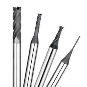
Precision Graphite Machining Solutions: Enhancing Quality Through Tooling and Process Optimization
Surface roughness, dimensional instability, and unpredictable tool life rarely stem from a single variable. In practical applications, these production bottlenecks occur when tools, machine tools, and cutting parameters lack proper alignment. Improving overall quality requires evaluating the entire manufacturing chain rather than treating symptoms in isolation.
Developing effective precision graphite machining solutions demands analyzing tool geometry, material hardness, cutting parameters, and spindle stability together. Engineers must assess target surface finishes, tolerance requirements, and cycle times before making adjustments. Establishing a synchronized machining ecosystem is the only way to achieve repeatable, high-precision production.
How Do High Precision Graphite End Mills Enhance Machining Stability?
Tooling selection remains a central factor governing consistency in complex graphite milling operations. During finishing passes, edge geometry, sharpness, and wear resistance directly dictate the final surface quality. Subtle cutter wear—even without catastrophic chipping—gradually increases surface roughness, causes dimensional drift, and leaves visible tool marks.
High-precision electrode milling requires cutters that maintain stable geometry throughout the entire tool life cycle. A reliable high precision graphite end mill must match specific graphite densities, cavity depths, and cutting strategies. Selecting purpose-engineered tooling is a foundational step toward establishing a robust manufacturing process.
How Do Diamond Coatings Improve Graphite Machining Efficiency?
Abrasive graphite dust creates severe friction that rapidly degrades uncoated carbide tools during long production runs. As edge wear progresses, surface quality fluctuates, leading to unexpected downtime for frequent tool swaps. Utilizing advanced tool coatings mitigates abrasive wear and extends periods of stable cutting.
Applying premium diamond coatings drastically improves wear resistance and machining efficiency under demanding conditions. However, protective coatings are not a universal fix for poor setups; their success depends on rigid machinery and optimized cutting parameters. Combining hard coatings with proper tool geometry delivers maximum economic efficiency in high-volume production.
How Do You Choose a Reliable Graphite End Mill Supplier?
Selecting a graphite end mill supplier requires evaluating technical process expertise rather than assessing catalog size alone. Persistent issues like erratic surface finish, short tool life, or deep-cavity chatter cannot be solved by simply swapping end mills. A trustworthy partner analyzes real-world operating conditions to provide tailored tooling recommendations.
Top-tier suppliers offer custom tooling strategies based on graphite grades, part drawings, machine dynamics, and target surface finishes. Resolving surface roughness or tool wear requires diagnosing root causes across the entire machining chain. Partnering with experienced applications engineers ensures long-term stability and superior part quality.
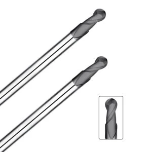
FAQ: Graphite Surface Roughness
In our extensive precision machining experience, clients frequently ask similar diagnostic questions regarding graphite surface roughness. Why do flawless initial passes gradually turn rough, show tool marks, or suffer particle chipping over time? Why do surface finishes remain unstable despite parameter tweaks? These issues stem from the complex interplay among material properties, tool wear, cutting parameters, and system rigidity.
To help engineers troubleshoot production bottlenecks faster, we compiled this quick-reference guide covering surface defect analysis, process control, and cutter selection. Grounded in real-world shop-floor data, these insights will help you evaluate your equipment, materials, and processes accurately. Use these solutions to restore process stability and achieve superior surface quality on demanding graphite parts.
Why Does the Graphite Surface Become Rough After Milling?
Increased graphite surface roughness after continuous milling is rarely caused by a single isolated variable. Factors like brittle particle pull-out, tool flank wear, high cutting loads, and dynamic vibration interact to destroy fine surfaces. Overly aggressive parameter settings accelerate these defects by fracturing the material matrix instead of shearing it cleanly.
When diagnosing surface quality drops, prioritize inspecting the tool edge condition, verifying speed-to-feed ratios, and checking vacuum efficiency. Re-cutting accumulated abrasive dust within deep cavities rapidly dulls sharp flutes and ruins fine surface details. Rough finishes are usually the cumulative result of process instabilities across the entire machining cycle.
How to Improve Graphite Surface Finish After CNC Machining?
Achieving a superior graphite surface finish requires simultaneous optimization across three core areas: cutting tools, process parameters, and process planning. Simply reducing feed rates or increasing spindle speeds without correcting tool wear or toolpath motion yields minimal improvement. A holistic strategy is mandatory for repeatable precision.
To ensure consistent surface quality, systematically review stock allowance distribution, toolpath continuity, cutting edge sharpness, and workholding rigidity. In precision EDM electrode manufacturing, controlling surface roughness dictates downstream electrical discharge performance and dimensional repeatability. Precise process control at the CNC mill prevents costly polishing rework later.
What Causes Graphite End Mills to Leave Machining Marks?
Visible surface patterns and machining marks are directly tied to dynamic tool performance during cutting passes. When a graphite end mill suffers minor edge wear, micro-chipping, or high spindle runout, it pushes material unevenly. This erratic mechanical action leaves prominent, repetitive vibration marks across finished workpiece faces.
If your setup produces unwanted tool marks, immediately inspect tool runout, toolholder clamping force, and total cutting hours. A cutter may not show catastrophic failure, yet its worn geometry can no longer maintain clean shearing action. Replacing dull end mills promptly restores surface finish and prevents dimensional drift.
Which Graphite End Mill is Best for Precision Graphite Machining?
No single cutting tool fits every precision graphite machining application seamlessly. Deep-cavity mold milling, intricate electrode details, and high-volume structural production each place unique demands on end mill geometry. Matching cutter design to specific material densities and target surface tolerances is essential.
Selecting optimal tooling requires evaluating graphite grain structure, cavity depth, machine dynamics, and required surface finishes. Continuous production shifts prioritize maximum wear resistance, whereas intricate finishing passes demand extreme edge consistency. Partnering with a specialized supplier ensures you deploy the exact tool geometry for your specific process requirements.






