


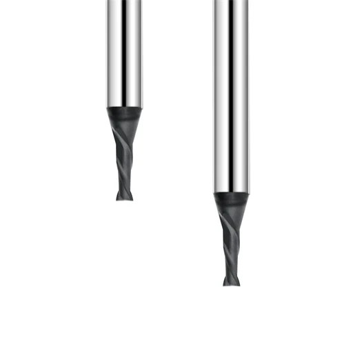
Over the past two decades of CNC machining, we have tackled countless high-precision graphite projects. We regularly produce EDM electrodes, complex mold components, and tight-tolerance graphite assemblies. Across various customer sites, one question arises repeatedly: why do results vary so drastically when using the same material, machine, and tool?
We recently assisted a client manufacturing premium EDM electrodes with imported graphite. During initial testing, they faced severe machining instability, including edge chipping during high-speed passes. Lowering the feed rate destroyed efficiency, while tool wear remained completely unpredictable. Our on-site analysis revealed the root cause: their graphite machining parameters did not match the specific material grade and tool geometry.
In actual production, graphite never allows for a “one-size-fits-all” parameter setup. Different material densities and grain sizes—such as fine-grain and ultra-fine grain graphite—demand tailored milling adjustments. Your specific combinations of spindle speed, feed rate, and depth of cut directly dictate surface quality and tool life.
Drawing from years of shop-floor experience, we compiled this Comprehensive Graphite Machining Guide. Our goal is to help engineers establish a systematic logic for parameter selection. By doing so, you can move away from costly trial-and-error and find your optimal machining window faster.
In this article, we analyze cutting parameters across roughing, semi-finishing, and finishing stages. We also discuss how to configure milling parameters based on your specific geometric requirements. Finally, we will explore how proper tool selection enhances overall process stability.
For most machine shops, tool selection determines the upper limit of parameter optimization. Standard carbide tools wear out too quickly to maintain consistent precision in abrasive graphite. Upgrading to a specialized diamond-coated end mill for graphite effectively reduces wear and stabilizes production.
Finding the best end mill for graphite requires evaluating more than just the initial tool price. Engineers must conduct a comprehensive assessment of material grade, machining strategy, and machine rigidity. This holistic approach ensures you achieve the best balance of tool longevity and part accuracy.
Through this guide, we translate decades of practical machining experience into actionable parameter selection methods. We want to help manufacturing enterprises reduce scrap rates and achieve highly stable graphite milling processes.
For any shop striving for high precision, the question is never “Can we machine this graphite?” Instead, you must ask: have you found the optimal graphite machining parameters for your specific setup?
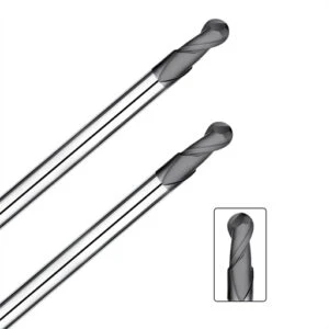
Fundamentals of Graphite Machining Parameters: Precision and Tool Life
In our two decades of CNC milling, we have found that most graphite defects do not stem from poor machine performance. Instead, they happen because operators fail to match their graphite machining parameters to the specific material grade and tooling. We often see shops run identical machines and graphite grades, yet experience wildly different tool life and dimensional stability due to mismatched feeds and speeds.
Through extensive shop-floor testing, we proved that stable graphite milling relies on a holistic approach. You cannot adjust a single setting in isolation; you must balance material grain structure, tool geometry, and machine rigidity. Finding the right graphite machining parameters allows you to strike the perfect balance between high efficiency, tight tolerances, and maximum tool longevity.
Impact on Efficiency, Surface Quality, and Tool Wear
Your chosen graphite machining parameters directly dictate three critical outcomes: production efficiency, surface finish, and tool wear rates. This balance becomes incredibly fragile when milling high-precision EDM electrodes or fine-grain graphite components. Even a slight miscalculation in your speed or feed settings can cause surface irregularities, which ruin subsequent electrical discharge machining processes.
During finishing phases, an aggressive feed rate increases the mechanical load on the cutting edge, triggering premature tool chipping. Conversely, overly conservative settings hurt your bottom line by destroying cycle time efficiency. To avoid these issues, we always optimize cutting conditions incrementally by analyzing graphite particle size, tool diameter, flute count, and depth of cut.
Balancing Speed, Feed, Axial Depth, and Radial Engagement
Throughout our CNC projects, we have mapped the clear relationship between spindle speed, feed rate, axial depth (Ap), and radial engagement (Ae). Many operators focus exclusively on spindle speed, but chip load and tool engagement area are equally vital for part stability. When milling deep cavities with small-diameter tools, we systematically reduce the width and depth of cut to eliminate harmonics and tool deflection.
For high-speed finishing operations, optimizing your graphite machining parameters requires balancing tool rigidity with overhang length. Excessive overhang introduces vibration, which rapidly degrades the cutting edge of solid carbide or diamond tools. By fine-tuning the radial and axial stepovers, you can maintain constant tool engagement and prevent catastrophic tool failure.
Reducing Edge Chipping and Dust Issues
Edge chipping and poor dust control are the two most frustrating challenges in graphite production. While shops often blame material quality or tool brands, our root-cause analyses usually point back to improper graphite cutting parameters. When cutting loads are too high, the impact fractures the brittle, granular structure of the graphite instead of shearing it cleanly.
These heavy impact forces cause severe chipping on thin-walled electrodes, sharp corners, and micro-features. Furthermore, incorrect graphite cutting parameters grind the material into a hyper-fine, airborne dust that threatens your machine’s linear guides. Optimizing your parameters alongside proper vacuum extraction ensures a cleaner shop environment and a stable, chip-free manufacturing process.
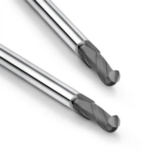
Guide to Graphite Milling Parameters: CNC Settings for Speed, Feed, and Depth of Cut
When machining precision components, your CNC settings are the ultimate factor influencing process stability. Machinists new to this material often apply feeds and speeds meant for standard non-metals or brittle ceramics. However, graphite possesses a unique granular structure and distinct fracture mechanics that make standard formulas fail, leading to heavy edge chipping.
Through extensive project testing, we developed a systematic approach to parameter adjustment rather than relying on generic handbook data. Establishing appropriate graphite milling parameters requires balancing material density, tool rigidity, and machine capability. Getting this foundation right is the only way to achieve consistent, high-precision results across different part batches.
Optimizing Spindle Speed (RPM) for Graphite Machining
Spindle speed is the first variable we evaluate during high-speed graphite milling projects. While many operators assume higher RPM always boots efficiency, our shop testing proves that over-speeding causes severe issues. With small tool diameters or long tool overhangs, excessive RPM amplifies harmonics and impact forces, which rapidly degrades the cutting edge.
When optimizing graphite cutting parameters, we adjust the RPM based on tool diameter, flute count, and coating type. For instance, diamond-coated tools on fine-grained graphite can handle much higher surface speeds due to their superior abrasive resistance. Conversely, for deep-cavity work, we lower the RPM to eliminate vibration and preserve tight dimensional tolerances.
Selecting Feed Rate and Chip Load in Graphite Milling
In actual production, we find that the feed rate affects tool life far more than spindle speed does. To shorten cycle times, many shops aggressively boost the feed rate without calculating the actual chip load. If the chip load exceeds the physical limits of the material, the high cutting pressure triggers severe edge breakout on the workpiece.
Therefore, we calculate the ideal chip load per tooth by analyzing the specific graphite grade and tool geometry. When finishing intricate EDM electrodes, we always prioritize dimensional stability and surface finish over maximum feed speed. During roughing phases, we optimize the feed to maximize the material removal rate without overstressing the tool.
Setting Depth of Cut Parameters for Roughing and Finishing
Choosing the right depth of cut (Ap and Ae) determines whether your graphite milling process succeeds or fails. The goal of roughing is rapid stock removal, which requires prioritizing chip evacuation and machine tool torque. For finishing, an excessive depth of cut introduces tool deflection, which completely ruins your final dimensional accuracy.
We always employ a phased approach tailored to the specific step of the machining process. During roughing, we set aggressive axial and radial depths based on tool size to maximize bulk material removal. When finishing complex 3D profiles, we drastically reduce the stepover and stepdown to optimize your graphite milling parameters for flawless surface quality.
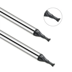
Graphite End Mill Parameters: Selecting Parameters Based on Tool Specifications
In precision manufacturing, matching your tool specs to your CNC settings determines the success of the job. Many shop owners focus only on tool material, coatings, and upfront prices when purchasing graphite end mills. However, failing to adjust your speeds and feeds based on flute count, diameter, and overhang length leads to rapid tool wear and poor surface finishes.
Our shop floor experience proves that no single data set applies to every milling application. Different tool geometries require entirely distinct cutting strategies; roughing requires maximum chip clearance, while finishing demands edge stability. Therefore, establishing correct graphite end mill parameters requires evaluating tool geometry, material grade, and machine tool rigidity as a unified system.
2 Flute Graphite End Mill Parameters: High-Speed Machining and Chip Evacuation
We typically select 2-flute graphite end mills for deep-cavity roughing where rapid dust and chip evacuation are critical. The wide, open flute valleys easily channel away the highly abrasive graphite dust generated during dry cutting. This efficient chip clearance drastically reduces the risk of secondary cutting, which is the leading cause of premature tool failure.
When configuring 2-flute graphite end mill parameters, we prioritize managing the mechanical cutting load and tool deflection. If you are milling deep EDM electrodes with an extended tool overhang, you cannot simply boost the feed rate. Instead, reduce the chip load per tooth while optimizing your tool paths to maintain stable, vibration-free cutting forces.
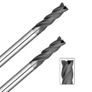
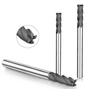
4 Flute Graphite End Mill Parameters: Optimizing High-Precision Finishes
We rely on 4-flute tools for the final finishing stages of precision components and complex EDM electrodes. The additional cutting edges increase tool engagement continuity, which significantly stabilizes your surface finishes. However, we always remind operators that more flutes do not automatically mean you can run more aggressive machining parameters across the board.
Optimizing 4-flute graphite end mill parameters requires focusing heavily on surface roughness, dimensional consistency, and harmonic control. When finishing ultra-fine grain graphite, reducing the feed per tooth minimizes tool marks and eliminates microscopic edge breakout. If your workpiece features tight pockets, you must re-evaluate your stepover to prevent dust packing.
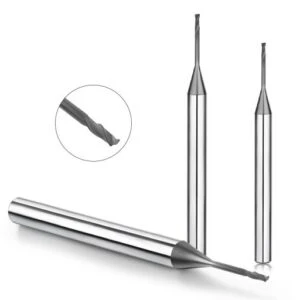
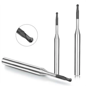
Parameters for Micro Graphite End Mills: Micro-Electrode Precision
In micro-machining projects, where tool diameters drop below 1mm, parameter control becomes incredibly unforgiving. Due to their microscopic core diameters and minimal rigidity, micro tools are highly sensitive to spindle runout and material brittleness. Consequently, the standard cutting formulas used for larger graphite end mills will instantly snap a micro tool.
For micro graphite end mill parameters, we drastically reduce the depth of cut and prioritize spindle balancing and high-precision tool holders. When milling micro-slots or intricate electrode ribs, we focus on cutting stability before attempting to optimize cycle times. In these high-stakes setups, controlled parameters are far more valuable than high material removal rates.
Graphite Milling Tools Selection: Matching Tools to Material Grades
In our decades of milling EDM electrodes and mold components, tool selection has always been the ultimate bottleneck for process stability. We regularly see shops invest in high-end CNC centers, yet still suffer from rapid tool wear and edge blowout. When we run the root-cause analysis, the culprit is almost always a mismatch between the tool geometry and the specific graphite grade.
Our practical projects have proven that a “universal” graphite tool simply does not exist. Different material granularities, machining stages, and tolerance zones require entirely distinct tooling strategies. To choose correctly, we must evaluate material properties, coating technology, and machine rigidity as a single system rather than buying tools based solely on price.
5 Key Factors to Consider When Choosing the Best End Mill for Graphite Machining
Clients frequently ask us to name the absolute best end mill for graphite production. In reality, the ideal cutter is always application-specific; what works for bulk roughing will ruin a thin-rib electrode. Your tooling choice must adapt to whether you are chasing maximum metal removal rates or flawless, micro-level surface finishes.
When advising shops, we analyze five key factors: substrate toughness, cutting-edge sharpness, flute clearance space, coating hardness, and overall tool rigidity. For instance, milling deep cavities with long-reach tools demands superior harmonic dampening to prevent deflection. Aligning these five physical tool traits with your specific part geometry is the only way to achieve stable production.
Solid Carbide vs Diamond Coated End Mills for Graphite
In daily production, we choose between solid carbide and diamond coated cutters based on production volume and tolerances. These options are not simple substitutes; they serve completely different cost and wear profiles. While uncoated carbide tools work fine for short, budget-sensitive prototypes, they fail quickly during long, continuous production runs due to graphite’s high abrasiveness.
For high-density graphite grades, we consistently deploy specialized diamond coated end mills for graphite. The micro-crystalline diamond layer acts as a shield, preventing abrasive particles from rounding the cutting edge and destroying part consistency. However, we still balance tool costs against total production volume, as premium coatings are not always necessary for low-tolerance roughing.
Tool Selection Strategies for Fine-Grain vs. Ultra-Fine Graphite
The primary differences between graphite grades come down to particle size, density, and the structural integrity of the material. Fine-grain graphite is the industry standard for precision EDM electrodes and molds. Meanwhile, ultra-fine graphite features a highly uniform, dense structure that allows for incredibly tight tolerances and flawless finishes, but it is highly abrasive.
We tailor the tool diameter, flute count, and coating to the exact grain structure of your material. For ultra-fine graphite requiring a mirror-like finish, we prioritize absolute cutting-edge integrity to prevent microscopic micro-chipping. By matching tool geometry directly to your specific material grade, you can instantly eliminate shop-floor trial and error.
Diamond Coated End Mills for Graphite: Optimizing Machining Parameters
In our two decades of milling EDM electrodes, progressive tool wear has always been the primary threat to production stability. Standard carbide tools can handle initial roughing, but abrasive graphite particles quickly dull the cutting edge over long production runs. Once the edge rounds, cutting forces spike, which immediately compromises your dimensional tolerances and causes micro-chipping on sharp part corners.
We recently resolved an issue where a client faced growing dimensional deviations after running just a few graphite electrodes. Our on-site analysis proved that the root cause was not their machine setup, but rather insufficient tool wear resistance. For high-volume or tight-tolerance projects, switching to specialized diamond coated end mills for graphite is the only way to stabilize your tool life and preserve part accuracy.
Why Diamond-Coated End Mills for Graphite Extend Tool Life
During long-term production, we have observed that tool failure is rarely caused by the hardness of the graphite material. Instead, it is caused by the continuous, severe abrasive action of the graphite’s micro-granular structure on the cutting edge. At high rotational speeds, these abrasive particles constantly sand down the tool, rapidly dulling any uncoated solid carbide edge.
Deploying diamond-coated end mills for graphite introduces an ultra-hard crystalline barrier that withstands this relentless abrasive friction. Shop-floor testing shows that diamond coatings maintain an incredibly sharp cutting edge for weeks rather than hours. However, maximizing this extended tool life still requires matching the tool’s diameter and flute geometry with proper parameter adjustments.
The Impact of Diamond Coating on Graphite Milling Parameters
Upgrading your tool coating alters your entire machining window, allowing you to run much more aggressive processing strategies. Because the diamond layer minimizes friction and resists heat buildup, you can safely boost your surface speeds and feed rates. This allows shops to shorten cycle times significantly without risking premature tool breakage or surface degradation.
Optimizing your graphite milling parameters requires finding the perfect balance between spindle RPM, chip load, and depth of cut. Overly conservative feeds will cause the tool to rub rather than cut, which actually accelerates diamond coating delamination. Conversely, exceeding machine limits introduces heavy harmonics, so we always establish the ideal window through short, incremental test cuts.
Matching Diamond-Coated Tools with CNC Graphite Machining Parameters
A common misconception among machinists is that buying a diamond-coated tool automatically allows for a blind increase in feeds and speeds. In reality, premium tooling is only one component of a larger manufacturing system. Your final part finish is heavily influenced by spindle runout, tool holder clamping force, and the rigidity of your setup.
When calibrating your graphite machining parameters for diamond-coated tools, you must first define your specific workpiece objectives. For intricate EDM electrodes, we prioritize dimensional accuracy by tightly controlling the chip load per tooth during finishing paths. By aligning tool specs, parameter logic, and robust dust collection, you can unlock the full value of high-performance diamond tooling.
Graphite Machining Parameters Chart
In precision graphite production, many engineers ask for a fixed formulas chart. However, our decades of shop-floor experience prove that a “one-size-fits-all” dataset simply does not exist for this material. Factors like graphite density, tool diameter, and machine rigidity completely change your cutting dynamics. Therefore, this graphite machining parameters chart serves as a logical baseline for step-by-step optimization rather than an absolute rulebook.
In daily operations, we set our baseline feeds and speeds using tool specifications and material grain size. From there, we fine-tune the numbers through short test cuts while closely monitoring spindle load, cutting harmonics, and dust patterns. For high-volume EDM electrode runs, this systematic approach is far more reliable than blindly trusting theoretical handbook values.
Graphite End Mill Parameters by Diameter
Tool diameter is the primary variable we use to calculate your baseline cutting data. Different cutter sizes feature vastly different core rigidities, chip clearance pockets, and maximum permissible tool loads. For instance, micro-tools require extremely light chip loads to prevent snapping, while large-diameter tools are built to handle heavy volumetric material removal rates.
When establishing your graphite end mill parameters, you must balance tool diameter, flute count, and the specific machining stage. A practical parameter chart must always define spindle RPM, linear feed rate, chip load per tooth (Fz), and your axial/radial depths of cut. Never look at these values in isolation; always adjust them based on real-time spindle vibration and surface finish results.
Recommended Parameters for Graphite Rough Machining
During heavy roughing phases, your primary objective is rapid, stable material removal rather than cosmetics or surface finishes. Therefore, we always prioritize tool core strength, chip pocket evacuation capacity, and machine torque over maximum cutting speeds. Your goal is to clear bulk stock efficiently without chipping the underlying structure of the workpiece.
To achieve this, we configure our graphite machining parameters chart data with heavier axial depths of cut (Ap) and conservative radial stepovers (Ae). This specific combination keeps a constant mechanical load on the tool, preventing harmful cutter chatter. For deep-cavity work, we also shorten the tool overhang as much as possible to eliminate deflection under heavy roughing forces.
Recommended Graphite Finishing Parameters
During finishing operations, your focus must shift completely from material removal volume to dimensional tolerances, surface roughness, and edge integrity. We frequently see shops run aggressive stepovers during finishing, which triggers micro-chipping along thin electrode ribs. By systematically dropping the cutting forces and smoothing out the tool paths, you can instantly eliminate these edge breakouts.
When optimizing your graphite finishing parameters, we drastically reduce the depth of cut and fine-tune the feed per tooth based on tool geometry. This step is incredibly vital when deploying diamond-coated tools, as a controlled chip load protects the premium coating from delamination. Ultimately, finishing parameters must prioritize structural consistency and flawless surface uniformity over raw cycle time.
Graphite Machining Problems: Troubleshooting Improper CNC Settings
In our two decades of milling EDM electrodes, we have found that most part defects do not stem from material flaws. Instead, they happen because operators fail to adjust their feeds and speeds to the actual setup rigidity. We frequently see shops run identical tooling and graphite brands, yet experience massive variations in tool life and surface finish due to mismatched cutting parameters.
Solving these common graphite machining problems requires balancing the tool, the workpiece material, and the machine kinematics as a single system. Incorrect settings prevent high-performance tools from shearing the material correctly, driving up scrap rates and manual rework costs. When troubleshooting on the shop floor, we always evaluate cutting loads, tool runout, and toolpath strategies rather than tweaking a single variable in isolation.
Low Parameters Cause Rapid Rubbing Wear and Low Efficiency
Machinists often lower their spindle speeds, feed rates, and cutting depths intentionally to “protect” their tools. However, our shop-floor testing proves that overly conservative machining conditions actually accelerate tool degradation. When parameters are set too low, the tool cannot establish a clean shearing action against the brittle graphite structure.
Instead of cutting, the tool edge rubs against the abrasive graphite particles, generating extreme friction that rapidly rounds the cutting edge. This rubbing wear is especially destructive when using micro-diameter tools for complex electrode ribs. To prevent this, we systematically recalibrate your graphite cutting parameters based on tool diameter and material density to maintain an optimal chip load.
Aggressive Parameters Trigger Edge Chipping and Dimensional Errors
Conversely, pushing cutting speeds and feed rates too high to force shorter cycle times destroys part quality. While graphite has excellent machinability, its low fracture toughness makes workpiece edges highly prone to breakout under excessive cutting pressure. This edge chipping is incredibly severe on thin-walled electrode ribs, sharp corners, and micro-features.
When optimizing your graphite cutting parameters, you must constantly monitor spindle harmonics, machining noise, and edge breakout. Excessive stepovers and stepdowns generate violent tool deflection, which instantly causes dimensional errors. For deep-cavity work with long tool overhangs, you must reduce the radial depth of cut to eliminate these destructive cutting forces.
Improving Stability by Optimizing Graphite Milling Parameters
Fixing unstable graphite production requires a holistic review of your entire machining process. Simply swapping a tool brand or changing a single speed setting only provides a temporary bandage. Achieving predictable, automated production requires a comprehensive approach that matches your tool geometry, coating technology, and machine dynamics.
Optimizing your graphite milling parameters starts by defining the material grain size to select the ideal tool diameter and flute count. From there, you must balance the spindle RPM, linear feed, and depth of cut to maintain a constant tool load. Finally, implementing aggressive vacuum dust evacuation and smooth, continuous toolpaths will ensure a highly stable manufacturing process.
Precision Graphite Machining Optimization: A Systematic Integration
In our two decades of precision manufacturing, we have realized that optimizing a single variable never resolves long-term production instability. While shops often hyper-focus on upfront tool life or raw cutting speeds, true floor success requires holistic system alignment. You must harmonize your CNC parameters, cutting tool geometries, toolpath strategies, and machine tool kinematics to achieve predictable results.
We recently solved a complex graphite electrode machining issue where a client faced severe dimensional drift despite running premium cutters. By systematically adjusting their cutting stepovers, minimizing tool overhang, and deploying smooth trochoidal toolpaths, we stabilized their entire automated line. We always advocate for this interconnected shop approach rather than wasting time tweaking isolated factors.
Synergistic Optimization of Parameters and Diamond Tools
Long-term shop data reveals a massive correlation between premium tool performance and your chosen graphite machining parameters. Even the most advanced diamond-coated cutters will fail prematurely if forced to run under incorrect cutting mechanics. Your parameters directly dictate the friction coefficient, coating wear rates, and part consistency during high-volume runs.
When matching your graphite machining parameters to diamond tooling, you must analyze tool diameter, substrate toughness, and the specific milling stage. For instance, fine-grain graphite allows you to push surface footage higher to leverage the diamond coating’s extreme abrasion resistance. Conversely, deep-pocket work requires lowering chip loads to eliminate harmonics caused by long tool extensions.
Establishing a Stable Machining Window in CNC Graphite Machining
The ultimate goal for any high-precision machine shop is establishing a wide, repeatable machining window. Most floor failures happen because a setup cannot handle slight variations during continuous, unmanned production runs. If your first part is perfect but the tenth part drifts out of tolerance, your process window is simply too fragile.
For stable CNC graphite machining, we log real-time spindle load, wear land growth, and surface finish degradation across long batches. We use this practical data to build a reliable parameter safety zone tailored to our specific machines and material densities. A robust window always factors in spindle thermal growth, axis acceleration limits, and dynamic dust extraction capabilities.
Comprehensive Workflow for High-Precision Electrodes
In actual production, we never treat parameter calibration as an isolated, one-time setup step. Instead, optimization is fully integrated into the entire manufacturing workflow, from initial material inspection to final quality control. We dynamically adjust our cutting logic across the roughing, semi-finishing, and finishing phases to meet tight target tolerances.
During graphite electrode machining, we match the initial tool specifications to the electrode’s rib geometry and target spark gap. Roughing phases focus entirely on bulk material removal rates and balancing tool loads to prevent catastrophic cutter breakage. Final finishing sweeps prioritize absolute edge integrity and surface uniformity, relying on highly controlled chip loads to eliminate micro-chipping.
Building a Stable Graphite Machining System
Our decades of floor experience prove that stable graphite milling is never achieved by changing a single parameter or buying a premium cutter. Instead, it relies entirely on the systematic interplay between your machine tool, workpiece characteristics, and cutting strategies. When these variables are properly harmonized, you can permanently eliminate the erratic tool life and unexpected edge breakout that plague most machine shops.
If your shop faces high scrap rates or unpredictable cycle times, start by auditing your current processing environment step-by-step. Check if your chosen graphite grade matches your tooling specs, and verify if your speeds, feeds, and depths of cut fit the specific operation. For high-precision setups, analyzing your blueprints and dialing in exact graphite machining parameters is far more effective than blindly replacing expensive equipment.
Summary of Graphite Machining Parameter Optimization
The core of parameter optimization is never about chasing the highest spindle RPM or forcing aggressive linear feed rates. True shop-floor profitability relies on finding the perfect equilibrium between volumetric material removal, dimensional tolerances, and tool longevity. Your programming strategies must dynamically pivot depending on whether you are executing a heavy bulk roughing pass or a delicate final finishing sweep.
When milling varying material densities, you must prioritize the relationship between grain size, cutter diameter, and your radial stepover (Ae). High-density graphite requires ultra-controlled chip loads to protect delicate part edges, while bulk pocket roughing demands massive chip evacuation spacing. Continually adjust your graphite machining parameters based on real-time spindle load and tool wear land growth rather than trusting static handbook data.
Selection Logic for the Best Graphite End Mill
When troubleshooting customer processes, we regularly find that severe machining defects stem from a complete mismatch between the tool geometry and the actual application. End mills feature wildly different core rigidities, flute angles, and coating thicknesses designed for specific roughing or finishing tasks. Selecting a tool based on brand popularity or upfront unit price alone almost always backfires during unmanned production.
To find the absolute best end mill for graphite production, you must first define your primary manufacturing constraint. If your priority is milling high-precision EDM electrodes with tight tolerances, you must select tools optimized for cutting-edge sharpness and dimensional stability. For simple geometries, focus on balancing tool lifecycle costs against target cycle times to keep your shop competitive.
Future Trends in Diamond-Coated End Mills for Graphite
The industry is rapidly shifting toward specialized diamond-coated end mills for graphite due to the growing demand for ultra-fine grain materials. Modern manufacturing requires extreme dimensional consistency over long continuous shifts, which uncoated carbide tools simply cannot deliver. However, the future of manufacturing relies on the precise, digital synergy between the diamond layer, the machine kinematics, and your program settings.
If your facility mills intricate EDM electrodes or complex high-volume molds, you must actively master the relationship between diamond coatings and real-time feeds. While the crystalline diamond shield provides unmatched abrasion resistance, its ultimate success depends entirely on proper chip load management and minimal spindle runout. Aligning these advanced tooling traits with robust shop-floor data is the only way to achieve true manufacturing automation.






