


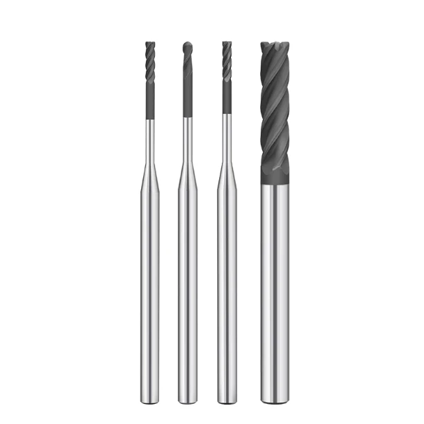
In precision graphite machining, a familiar pattern often frustrates machinists. A brand-new graphite end mill performs smoothly at first. Then, after several hours—or just dozens of cycles—the surface finish deteriorates, dimensions begin to drift, and micro-chipping appears on the cutting edge. Strangely, different machine shops running the same grade of graphite with identical cutting tools often report vastly different tool life.
Working with clients across semiconductor components, graphite electrodes, and mold making, we see this scenario regularly. While operators quickly blame poor cutter quality, on-site telemetry reveals a different story. Graphite end mill wear depends on much more than tool substrate. Tool geometry, cutting parameters, machining dynamics, and abrasive dust control all directly impact cutter longevity.
Graphite is brittle yet extremely abrasive. High-speed milling generates fine, dry graphite dust that constantly erodes the cutting edge. Without the correct relief angles, chip clearances, and feed-per-tooth settings, even high-grade carbide end mills wear out prematurely.
Evaluating a milling cutter requires assessing the entire tool life cycle, not just initial cycle tests. True performance means consistent dimensional stability, minimal flank wear rates, and reliable part finishes over time.
Many shops upgrade to diamond-coated graphite end mills for superior abrasion resistance. While diamond coatings provide a tough protective barrier against particle erosion, coating technology alone is not a silver bullet. Maximizing tool life requires balancing tool geometry, tuned feeds and speeds, and effective vacuum dust extraction.
When your graphite end mills wear out prematurely or cause part tolerance issues, the root cause is rarely the cutter alone. Pinpointing whether the issue stems from your tooling specs, feed rates, or dust evacuation is the true key to stabilizing your milling process.
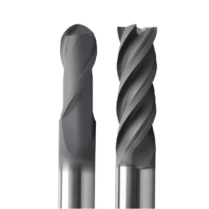
Graphite End Mill Tool Life Analysis: Why Do Graphite End Mills Have Shorter Lifespans?
In our years of supporting graphite electrode, mold, and semiconductor component manufacturing, graphite end mill tool life remains a top operational challenge. Machinists often report erratic results even when running identical graphite grades, CNC centers, and tool specs. While some cutters run smoothly for hours, others quickly generate higher cutting forces, poor surface finishes, and out-of-spec tolerances.
A cutter’s lifespan depends on a dynamic machining ecosystem rather than a single parameter. Graphite material density, grain size, spindle runout, machine rigidity, and vacuum dust extraction all dictate performance. In high-speed milling, ignoring the synergy between tool geometry and process dynamics will drastically shorten the lifespan of even premium solid carbide cutters.
Factors Affecting Graphite End Mill Lifespan: Material, Machining Environment, and Tool Condition
We always evaluate the graphite grade first when troubleshooting premature tool failure. Material hardness, particle size, and pore distribution directly govern the rate of abrasive flank wear. High-density ultrafine graphite yields exceptional surface finishes, but its compact structure increases continuous friction and thermal load, shortening graphite end mill lifespan.
The machining environment plays an equally vital role on the shop floor. In deep-pocket cavity milling, weak vacuum extraction allows abrasive dust to pack around the flutes. The tool then recuts these particles, accelerating edge degradation. Achieving predictable tool life requires balancing feed rates, dry-air blasts, dust management, and toolholder runout alongside substrate selection.
Mechanisms of Graphite End Mill Wear: How Graphite Particles Cause Tool Wear
Graphite cutting differs fundamentally from metal cutting because graphite fractures as a brittle powder rather than shearing into chips. Highly abrasive micro-particles constantly blast against the cutting edge during high-speed rotation. This continuous scouring causes severe abrasive wear, edge rounding, and micro-chipping, which defines classic graphite end mill wear.
Early abrasive wear rarely causes sudden catastrophic breakage on the CNC machine. Instead, operators first notice altered cutting acoustics, heavier dust clouds, increased surface roughness, and burred electrode corners. Running a dull cutter past this stage spikes mechanical loads, causing edge chipping, thermal cracking, and loss of dimensional accuracy.
Common Signs of Reduced Tool Life in CNC Graphite Machining
Long-term process audits show that end mill degradation always gives clear early warning signals. Machinists will spot fine micro-striations on part walls, dull electrode corner definitions, or subtle shifts in cutting tone. Spotting these physical cues early allows operators to measure tool wear before parts fall out of tolerance.
The core failure in many machine shops is not catching tool wear in its early stages. Operating without dynamic adjustments to spindle speeds, feeds per tooth, or stepovers accelerates cutter failure. We recommend monitoring active tool conditions via real-time cut quality rather than relying solely on arbitrary, fixed-time tool change schedules.
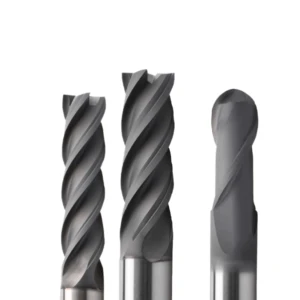
Causes of Graphite End Mill Wear: Key Factors Leading to Rapid Tool Wear
Rapid tool degradation remains one of the costliest hurdles in high-volume CNC graphite shops. Operators often find that new cutters perform flawlessly during the first few cycles, but early surface roughness, dimensional drift, and dull edges soon appear. Multi-facility machining data confirms that graphite end mill wear is rarely caused by a single defect; it stems from a compounding mix of abrasive dust, brittle fracture dynamics, and mismatched speeds.
Unlike ductile metals that form continuous chips, graphite fractures through brittle micro-cracking during cutting. This mechanism continuously pelts the cutting edge with hard carbon grains under high-frequency impact loads. Without optimized feed-per-tooth settings and rigid toolholder engagement, cutting edges dull quickly, driving up machining costs and causing premature part rejection.
Wear Caused by Graphite Dust: How Dust Accelerates Cutting Edge Damage
Inadequate dust extraction quietly ruins tool life across many production floors. When fine graphite particles fail to evacuate the cut zone instantly, they pack tightly into tool flutes and pocket crevices. This creates severe secondary abrasion, grinding down the relief angle much faster than clean cutting. Upgrading industrial vacuum suction often doubles tool life without changing a single cutting parameter.
Diagnostics revealed that trapped graphite machining dust was forcing the flutes to continuously re-grind abrasive debris. Maintaining a stable, long-run machining cycle requires combining high-velocity dry air blasts with localized extraction hoods to keep the cutting path completely clear.
Graphite Edge Chipping: Edge Failure When Machining Brittle Materials
Maintaining edge integrity is just as critical as managing steady flank wear when milling fine-grain electrodes. Sudden load spikes, improper entry ramping, or weak flute geometries easily trigger micro-fractures along the tool edge and workpiece perimeter. This causes noticeable graphite edge chipping, ruining delicate thin ribs, sharp corners, and tight chamfers.
Edge failures typically start as microscopic chipping along the cutter radius rather than sudden catastrophic breakage. These micro-defects leave burrs along electrode profiles, create rough sidewall steps, and distort EDM spark gap accuracy. Protecting brittle workpiece features requires rigid tool cores, honed cutting edge preparations, and stable trochoidal toolpaths that prevent shock loading.
Excessive Wear and the Impact of Cutting Heat in High-Speed Machining
Ramping up spindle RPM without balancing feed rates frequently triggers accelerated thermal and abrasive tool failure. While graphite dissipates heat faster than titanium or stainless steel, friction from continuous high-speed contact and packed dust still creates concentrated localized heat. This thermal buildup degrades tool coatings and weakens the carbide substrate matrix.
Balancing your graphite machining speed and feed against cut depths and tool diameters is crucial for tool longevity. Running micro-end mills with heavy stepovers accelerates edge dulling, while deep axial cuts in tight cavities induce harmonic chatter and uneven flute wear. Tuning speeds to match flute count, graphite grain size, and pocket geometry guarantees maximum material removal rates with predictable tool wear.
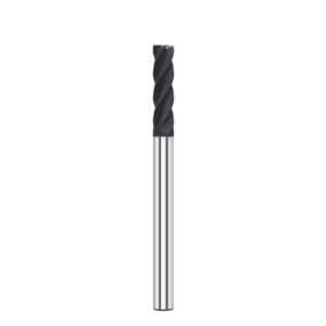
Optimizing Graphite End Mill Geometry: How Tool Structure Affects Service Life
Field telemetry across electrode and semiconductor milling lines reveals a consistent pattern: tools sharing identical carbide grades often show wildly different lifespans due to macro-geometry variations. When cutters dull prematurely, machinists typically tweak spindle RPM or table feeds first. However, the fundamental graphite end mill geometry dictates process stability, cutting dynamics, and overall tool longevity.
Optimizing tool architecture balances material removal rates with structural wear resistance. Milling brittle graphite requires fast, non-clogging dust evacuation without compromising cutting-edge rigidity. Undersized chip flutes, weak web cores, or improper relief clearances induce chatter, degrade surface finishes, and cause premature edge failure regardless of your CNC controller settings.
The Impact of Flute Count on Graphite End Mill Tool Life
Selecting flute count requires balancing flute volume against cutter core strength. Two- and three-flute end mills offer generous chip valleys, ensuring rapid dust clearance during roughing, slotting, and deep-pocket clearing. Four-flute tools provide greater peripheral rigidity and tooth density, making them ideal for high-speed finishing and light stepovers.
We recently audited a shop where four-flute cutters packed tight with dust when slotting dense graphite blocks, causing rapid abrasive failure. Switching to a two-flute tool expanded chip clearance, dropping cutting temperatures and extending graphite end mill tool life. Matching flute count to cavity depth, material density, and axial engagement ensures clean evacuation and predictable tool life.
The Role of Helix Angle and Cutting Edge Design in Wear Control
Helix angles control cutting force distribution, axial thrust, and chip flow direction. Moderate helix angles (around 30° to 35°) ensure smooth edge engagement and reduce impact shock when entering dense graphite blocks. An improper helix angle creates severe harmonic vibration, subjecting the cutting flutes to continuous micro-impacts that accelerate flank wear.
Engineering a durable graphite cutting edge design requires dialing in rake angles, primary reliefs, and corner preparations. Razor-sharp positive rakes cut smoothly initially, but quickly micro-chip under abrasive friction. Light edge hones or micro-chamfers significantly bolster cutting-edge strength, damping vibration and stabilizing long-term milling cycles.
How Sharp Cutting Edges Reduce Graphite Edge Chipping
Machining delicate rib geometries and sharp electrode corners demands exceptional cutting-edge consistency. Poor edge conditions tear brittle carbon grains rather than shearing them cleanly, causing jagged part profiles. A tuned, sharp cutting edge drastically reduces cutting pressure, preventing ragged sidewalls and eliminating costly secondary bench finishing.
However, maximum sharpness is not always optimal across every graphite grade. Razor-thin edges lack the mechanical mass needed to resist abrasive micro-fractures, which actually increases the risk of graphite edge chipping. Applying controlled edge hones paired with tough diamond coatings delivers the ideal balance of sharpness, impact toughness, and wear resistance.
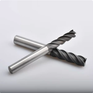
Optimizing Graphite End Mill Cutting Parameters: How Speed and Feed Affect Tool Life
Improper cutting parameters cause premature tool failure on the shop floor just as often as incorrect cutter geometry. Many machinists mistakenly apply metalcutting logic to carbon, aggressively ramping up spindle RPM and table feeds to cut cycle times. However, graphite’s brittle fracture mechanics require a dialed-in approach that balances particle abrasion, cutter diameter, and tool engagement.
There is no universal speeds-and-feeds formula that fits every graphite milling application. Roughing, semi-finishing, and fine detailing each demand distinct chiploads and stepovers—even when using the same tool diameter. Chasing maximum feed rates without monitoring tool deflection leads to rapid cutting-edge rounding, burred electrode ribs, and unstable production cycles.
The Impact of Graphite Machining Speed and Feed on Tool Wear
Evaluating cutting speed (SFM) and feed-per-tooth (chipload) is our first step when auditing tool wear. Running surface speeds too high increases abrasive friction frequency against the cutting edge, while underfeeding causes the flutes to rub rather than cleanly fracture the carbon grains. Maintaining balanced cutting dynamics prevents severe flank scouring and premature edge rounding.
During an EDM mold electrode audit, a shop increased table feed to cut cycle times without adjusting axial depth of cut. While parts came off faster initially, flank wear tripled and sharp corners chipped. Re-tuning their graphite machining speed and feed restored the correct chipload, stabilizing cutting forces and extending tool life across long production runs.
Reduced Tool Life Caused by Incorrect Spindle Speed and Feed Rate
Tool degradation frequently stems from a mismatch between RPM and table feed rather than speed alone. High spindle speeds paired with low feeds force the cutting edge to burnish against abrasive graphite dust, accelerating thermal and abrasive wear. Conversely, overfeeding slender tools exceeds core rigidity, creating cutting edge micro-chipping and harmonic chatter.
Dialing in cutting parameters requires evaluating tool diameter, flute count, tool overhang, graphite grain size, and machine rigidity. In deep-cavity electrode milling, extended-reach toolholders amplify radial deflection, making standard handbook parameters unstable. Machinists should adjust feed rates dynamically based on acoustic feedback, dust flow, and real-time spindle load.
Optimizing Depth of Cut to Extend Graphite End Mill Lifespan
Depth of cut directly governs cutting forces, radial tool deflection, and spindle vibration. Machinists often push heavy axial depths ($a_p$) to eliminate passes, but this spikes radial tool pressure on small-diameter end mills. This deflection induces chatter, causes taper error on vertical walls, and breaks fragile tool corners.
We recommend separating engagement strategies by machining stage to maximize graphite end mill lifespan. Roughing passes benefit from shallow axial cuts paired with wide radial stepovers—or modern high-feed trochoidal toolpaths—while finishing passes require light, uniform stock engagement to prevent tool push-off and ensure crisp electrode rib definition.
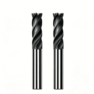
Diamond Coated Graphite End Mills: A Solution for Extending Tool Life
When milling high-density graphite for EDM electrodes, mold cores, and semiconductor fixtures, uncoated carbide tools struggle during long cycles. Operators frequently face tool offset drift, corner degradation, and rising scrap rates. Selecting dedicated wear-resistant tooling is essential to maintain tight tolerances and lower part-rejection rates during extended production runs.
Upgrading to diamond coated graphite end mills provides the extreme abrasion resistance needed to combat rapid carbon particle erosion. Genuine CVD diamond coatings create an ultra-hard barrier that prevents flank scouring and stabilizes spindle loads. Unlocking maximum tool life still requires matching diamond film adhesion with rigid tool substrates, tuned geometries, and optimized chip loads.
Why Do Diamond-Coated Graphite End Mills Offer Superior Wear Resistance?
Standard carbide cutters fail in graphite due to relentless micro-abrasion that rounds cutting edges and wears down clearance angles. As flank wear grows, cutting forces spike, deflecting thin ribs and leaving rough, gouged surfaces. The extreme hardness of diamond coatings shields the carbide substrate from continuous particle scouring.
Machine shops achieve the best return on investment by deploying coated tools on demanding, high-precision jobs. While uncoated carbide works for brief prototypes or coarse roughing, diamond-coated cutters are essential for micro-milling, tight-tolerance EDM electrodes, and continuous production. Choosing the right coating solves specific wear patterns, stabilizes surface finishes, and keeps cycle times predictable.
Tool Life Comparison: Carbide vs. Diamond-Coated Graphite End Mills
Uncoated solid carbide end mills offer a lower initial unit price, making them suitable for low-volume runs and soft, coarse-grain graphite. However, as cycle times lengthen or graphite density increases, carbide cutting edges dull rapidly, requiring frequent operator intervention. In head-to-head shop tests, diamond-coated tools regularly outlast standard carbide by 5 to 10 times under identical feed rates.
Evaluating overall graphite end mill lifespan requires looking beyond the tool purchase price to the total cost per part. For short, one-off jobs, premium coated tooling may not yield measurable ROI. True cost savings emerge in lights-out production, where extended tool life eliminates mid-cycle tool changes, preserves spark-gap accuracy, and reduces spindle downtime.
How to Choose the Right Supplier for High-Precision Diamond-Coated Graphite End Mills?
Evaluating a cutting tool vendor requires assessing far more than whether they apply diamond coatings. Substrate cobalt content, chemical etching preparation, coating adhesion, and edge hone micro-geometry dictate whether a tool succeeds or delaminates. For micro-machining and thin-rib electrodes, consistent batch-to-batch edge prep is far more vital than a single catalog test run.
When qualifying a diamond coated graphite end mill supplier, partner with manufacturers that understand real-world CNC graphite dynamics. Top-tier tooling suppliers provide tailored geometry recommendations, application-specific speed and feed charts, and custom diamond thickness options. Aligning tool manufacturing precision with your specific machine rigidity ensures you extract full value from high-performance diamond tooling.

How to Extend Graphite End Mill Tool Life and Enhance Machining Performance?
Extending tool life in production graphite milling is never achieved through a single quick fix. Operators often upgrade to expensive cutters only to find wear rates unchanged because tool geometry, feeds and speeds, dust extraction, and spindle dynamics remain uncalibrated. A holistic process review is necessary to stop premature edge failure and stabilize cycle times.
When tackling rapid graphite end mill wear or surface roughness, audit the full cutting setup. Verify whether tool relief matches material abrasiveness, chiploads prevent rubbing, and vacuum hoods clear debris instantly. In our experience, maximizing graphite end mill tool life requires synchronizing the entire machining ecosystem rather than simply switching tool brands.
Optimizing Graphite Machining Parameters to Reduce Tool Wear
When milling dense graphite electrodes or deep cavities, cutting parameter validation must be your first diagnostic step. Accelerated flank wear rarely comes from poor substrate quality alone; it usually stems from an imbalance between RPM, feed rate, and cut depth. Overfeeding overloads the cutting edge, while underfeeding causes the flutes to burnish against abrasive carbon grains.
We recommend fine-tuning speeds and feeds based on tool reach, flute count, and graphite grain size rather than relying on generic handbook charts. If you notice early edge dulling, harmonic chatter, or rough part walls, log spindle load across incremental feed steps. This telemetry identifies the sweet spot where cutting forces remain low and tool wear stays predictable.
Improving Graphite Machining Dust Control to Enhance Stability
Continuous, lights-out graphite milling demands aggressive dust evacuation at the cut zone. Severe tool degradation is frequently caused by secondary particle abrasion rather than initial chip fracture. When fine graphite dust packs into deep pockets, rotating flutes repeatedly grind trapped debris, rapidly eroding tool clearances.
High-velocity dry air blasts paired with dedicated vacuum extraction hoods dramatically improve tool consistency in deep-rib electrode machining. Upgrading your graphite machining dust control often doubles tool life without altering feed rates or tool substrates. If you see packed flutes, sidewall scratches, or erratic tool wear, prioritize optimizing your extraction system.
Establishing a Comprehensive Graphite Machining System to Extend Tool Life
Lowering cost-per-part requires shifting from isolated troubleshooting to a total machining system approach. Consistent electrode quality relies on the complete synergy between tool substrate, diamond coating quality, spindle runout, dynamic toolpaths, and operator protocol. A weak link in any single area quickly degrades performance across the line.
We evaluate parts by reviewing material density, cavity depth, machine rigidity, and required spark gap tolerances together. Tool geometry directly dictates chip evacuation volume, cutting parameters determine edge loads, and the extraction setup controls abrasive wear rates. Mastering this interconnected process ensures maximum cutter longevity and repeatable CNC graphite performance.
Graphite End Mill Wear – FAQs
Tool wear remains the most frequent technical hurdle for machinists running graphite electrodes, mold cores, and semiconductor fixtures. Shop teams rarely lack basic tooling knowledge; instead, they struggle with unpredictable tool life, dimensional drift, and tricky parameter tuning on abrasive carbon grades.
To help troubleshoot these floor challenges, we compiled real-world solutions to common shop inquiries. This practical FAQ breaks down tool life expectations, rapid wear root causes, coating suitability, and parameter calibration. Use these field-proven benchmarks to audit your machining setup and stabilize daily cycle performance.
How long does a graphite end mill last?
There is no universal operational lifespan for a cutter because tool degradation depends heavily on graphite grain size, part geometry, tool diameter, and machine dynamics. A cutter running soft, coarse-grain stock will last significantly longer than the same tool milling dense, ultrafine-grain EDM electrodes under identical feeds.
When evaluating graphite end mill lifespan, look beyond raw spindle hours and track completed parts, edge sharpness, and wall tolerances. Acoustic pitch shifts, heavier dust plumes, corner burring, and dimensional taper indicate that your cutting edge has degraded and requires immediate inspection.
Why does my graphite end mill wear quickly?
Field failure audits show that premature cutter wear rarely stems from substrate defects alone. Instead, it is usually triggered by abrasive carbon dust recutting, poor chipload control, or mismatched tool macro-geometry.
Primary causes of accelerated graphite end mill wear include secondary dust abrasion, micro-chipping from aggressive stepovers, and friction from underfeeding. If you observe early edge dulling or rough part walls, immediately verify toolholder runout, spindle speed, chipload per tooth, and vacuum extraction velocity.
How can I extend graphite end mill lifespan?
Maximizing cutter longevity requires synchronizing your tooling geometry, feeds and speeds, dynamic toolpaths, and vacuum dust extraction rather than simply buying higher-priced cutters. Maintaining rigid, balanced toolholding and high-velocity air blasts dramatically reduces abrasive friction and thermal wear.
We recommend tracking active tool conditions by logging spindle runtime, material grade, chiploads, and wear patterns across production cycles. Logging tool wear telemetry eliminates guesswork, allowing operators to fine-tune graphite end mill tool life and program automated tool changes before parts fail inspection.
Is a diamond-coated graphite end mill better for graphite machining?
Upgrading to diamond-coated graphite end mills is the industry standard for high-volume runs, dense graphite grades, and lights-out EDM electrode manufacturing. The extreme hardness of genuine CVD diamond shields the cutting edge from abrasive carbon scouring, maintaining razor-sharp profiles for hours.
For short prototype runs, soft graphite grades, or coarse roughing, uncoated carbide end mills remain a cost-effective alternative. Selecting coated versus uncoated cutters requires balancing initial tool procurement cost, cycle volume, part tolerance limits, and required spindle uptime.
What graphite machining speed and feed should I use?
Graphite milling parameters cannot be copied directly from metalcutting charts because optimum settings vary by cutter diameter, flute count, material density, and machine rigidity. High-speed spindles generally demand light chip loads and smooth, continuous radial stepovers to prevent edge chipping.
We recommend establishing a chatter-free baseline with your graphite machining speed and feed before pushing for maximum material removal rates. Overly aggressive feeds trigger shock loads and edge chipping, while underfeeding causes rubbing; run incremental step-tests to identify the sweet spot for your machine setup.






