


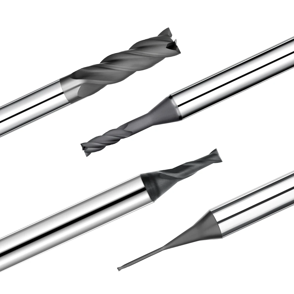
A client recently reached out regarding a graphite electrode machining project where standard carbide tools were failing prematurely. While initial parts passed inspection, the cutting edges dulled rapidly during continuous runs. Dust generation surged, tool change frequency spiked, and profile accuracy degraded. The customer assumed the graphite grade was defective, but our on-site analysis revealed the root cause: an engineered mismatch among the tool structure, cutting parameters, and machine setup.
Rapid graphite end mill wear remains one of the costliest challenges in EDM electrode production and precision mold making. Many shops focus solely on tooling unit costs rather than the underlying wear mechanisms. Graphite machining does not form standard ductile chips; instead, it generates fine, abrasive particles that act like grinding compound against the cutting edge.
In production environments, this abrasive degradation manifests as micro-chipping, rapid diameter reduction, and poor surface finishes. Simply slowing down feed rates or swapping tools frequently will not solve the issue. Real tool life extension requires a systematic approach that balances tool geometry, flute design, chip evacuation, and coating technology.
Upgrading to diamond-coated end mills significantly increases abrasion resistance in high-density graphite. However, premium coatings alone cannot compensate for aggressive depth of cut, excessive chipload, or inadequate dust evacuation. True machining stability requires matching the tool substrate and coating directly to your spindle dynamics and material hardness.
In this guide, we break down why graphite accelerates cutting edge wear and how custom graphite end mill designs resolve these challenges. We explore core dust wear mechanisms, geometric optimizations, and parameter tuning based on practical shop-floor data.
For CNC engineers manufacturing precision graphite electrodes, tool longevity is not about buying the most expensive cutter. It is about aligning tool geometry, substrate coating, and cutting parameters into a cohesive strategy. Is an unoptimized machining setup quietly eating into your tooling budget and part accuracy?
Graphite End Mill Wear Analysis: Why Does Graphite Machining Lead to Rapid Tool Wear?
In our years of mold and electrode machining, tool longevity remains a primary production bottleneck. We recently audited a mold shop where identical cutting programs produced clean parts initially, but cutting edge degradation surged during extended cycles. Our on-site evaluation showed that premature failure was not caused by raw material flaws, but by an unmanaged combination of abrasive cutting action, machine parameters, and tool substrate mismatch.
A core driver of this instability is chronic graphite end mill wear. Unlike ductile metals that generate continuous chips, brittle graphite shears into millions of microscopic granules that repeatedly batter the cutting edge. Without engineered tool geometry, proper speeds and feeds, and synchronized dust extraction, abrasive friction steadily builds up. This progression leads to micro-chipping, dimensional drift, and unacceptable surface finishes.
Graphite Tool Wear Mechanism: How Do Graphite Particles Cause Abrasive Wear?
Analyzing failed cutters in high-speed milling cells reveals distinct abrasive patterns along the primary relief. The cutting edge rarely suffers immediate catastrophic breakage from excessive cutting forces. Instead, the tool gradually loses its cutting geometry through relentless, micro-scale friction against abrasive particles during extended finishing passes, accelerating graphite tool wear across fine electrode details.
On the shop floor, the rate of degradation depends on graphite grain size, bulk density, tool substrate toughness, and edge hone radius. Fine-grain, high-density graphite delivers superior surface finishes, but its compacted grain structure places higher abrasive demands on the cutter. Applying a general-purpose end mill quickly rounds the cutting edge, spikes cutting pressure, and degrades machining stability.
Graphite Dust Wear: How Graphite Dust Accelerates Cutting Edge Damage
Airborne particulate management inside the CNC enclosure directly affects cutter lifespan. In one field audit, an EDM shop experienced severe premature tool failure despite using conservative feed rates. The culprit was poor extraction: dense pockets of airborne powder were recirculating directly back into the cut zone, triggering severe graphite dust wear.
In dry machining setups, unevacuated dust acts like an abrasive lapping paste between the flute and the workpiece. This trapped powder increases cutting friction, retains localized heat at the cutting zone, and accelerates flank wear. Optimizing dust collection hoods, air blast direction, and toolpath strategies minimizes secondary abrasion and protects your finished electrode geometry.
The Impact of Graphite Material Properties on End Mill Wear
A common misconception in the shop is that graphite’s low hardness makes it easy on tooling. In reality, the material’s brittle fracture mechanism and micro-grain structure subject the tool to continuous micro-impacts. These dynamics accelerate graphite end mill wear far faster than many abrasive non-ferrous metals, making proper grade selection critical.
High-density EDM grades with sub-micron grains require sharp, abrasion-resistant diamond tooling to hold tight rib tolerances. In contrast, bulk roughing applications prioritize impact toughness and aggressive chip clearance. Successful graphite milling relies on tailoring tool geometry, substrate hardness, and parameter strategies to the exact graphite grade rather than relying on a standard, one-size-fits-all end mill.
Analysis of Key Factors Affecting Graphite End Mill Lifespan
Tool longevity in graphite electrode production is rarely determined by the cutter alone; it depends heavily on process synergy. We recently audited an EDM mold shop running identical graphite blocks and cutters across multiple shifts, yet tool life varied widely between operators. Telemetry logs showed major disparities in spindle speeds, chip loads, axial step-downs, and lead-in strategies across runs.
Maximizing your graphite end mill lifespan requires evaluating the complete cutting ecosystem. When feeds, speeds, and depths of cut deviate from their sweet spot, localized tool loading spikes and triggers accelerated flank degradation. Rather than locking in rigid handbook charts, machinists should dynamically balance workpiece grain structure, cutter geometry, machine rigidity, and cycle targets.
How Do Graphite Machining Parameters Affect Tool Lifespan?
Optimizing cycle times begins by aligning machining parameters with the mechanical limits of the cutting edge. Operators often push spindle RPM and table feed to shorten cycle times, but aggressive moves often backfire. Overloading the cutter causes erratic cutting forces, thermal spikes, micro-chipping, and severe dimensional drift on critical electrode ribs.
Field data confirms that dialling in graphite machining parameters is essential for tool life extension. For example, pushing axial depth too hard on miniature end mills induces tool deflection and chatter. Conversely, feeding too slowly during finishing causes rubbing rather than shearing, accelerating abrasive flank wear. Dynamic adjustments based on cutter diameter, graphite density, and engagement angles yield the best results.
The Impact of Cutting Speed, Feed Rate, and Depth of Cut on Graphite Tool Wear
Inspecting worn cutters under a toolmaker’s microscope reveals clear patterns of parameter mismatches. Excessive surface footage drives friction-induced rounding of the cutting edge. Inadequate chip load forces the tool to burnish the graphite, while excessive radial or axial depth of cut spikes deflection forces and induces chatter, drastically accelerating graphite tool wear.
In one deep-rib electrode project, a shop tried cutting cycle times by doubling the axial step-down per pass. This caused heavy tool deflection and frequent edge chipping. By switching to a high-speed trochoidal toolpath with lighter radial engagement and higher feed rates, tool life increased threefold while cycle times remained steady. Managing tool wear demands balancing cutting forces, tool rigidity, and dust evacuation.
How Does an Unstable Machining System Shorten Graphite End Mill Lifespan?
Beyond cutting feeds and speeds, machine setup dynamics directly dictate cutter longevity. High spindle runout, low-rigidity toolholders, inadequate clamping, or table resonance subject the cutting edge to continuous micro-impacts. While these micro-vibrations might not cause immediate catastrophic breakage, they degrade the edge hone and accelerate chipping.
In high-precision graphite milling, system stability covers every link from toolholding collets to vacuum extraction velocity. When troubleshooting short tool life, experienced CNC engineers audit the entire process chain instead of blaming the cutter. Eliminating spindle vibration and unevacuated dust is vital to achieving the expected graphite end mill lifespan and maintaining sub-micron electrode tolerances.
Optimizing Graphite Machining Systems: Methods to Reduce Rapid Tool Wear
Premature tool failure in electrode manufacturing is rarely just a cutter defect; it usually points to a lack of complete process control. We recently audited an EDM facility where identical end mills produced drastically different lifespans across separate machine cells. The investigation showed that machine resonance, poor vacuum suction, and erratic step-overs were silently degrading cutting performance.
Establishing a rigid, balanced graphite machining system is essential for consistent tool wear management. While cutting forces in graphite are relatively low, the material’s brittleness and abrasive dust amplify any slight mechanical instability. Spindle runout exceeding 0.0001 inches, long tool overhangs, or weak workholding introduce harmonic chatter that rapidly chips micro-edges, demanding a holistic setup optimization.
Stability Control in CNC Graphite Machining Systems
Unstable machining setups remain the leading cause of unexpected micro-chipping on precision rib electrodes. Using excessive tool stick-out or low-rigidity collets causes cutting edge deflection under load, even when programmed speeds and feeds appear conservative. Over time, these dynamic micro-impacts ruin the edge hone and lead to dimensional drift on critical EDM features.
Engineering a stable CNC setup requires auditing spindle runout, utilizing balanced shrink-fit or hydraulic holders, and reinforcing part clamping. Maintaining smooth, continuous tool engagement is far more effective than simply ramping up spindle speed. Dampening vibration in deep cavity milling protects delicate cutting edges and guarantees consistent graphite machining quality across high-volume production runs.
How to Reduce Wear Caused by Graphite Dust in Dry Machining?
Because graphite is machined dry, particulate management plays a direct role in cutting edge survival. We once diagnosed a sudden drop in cutter life where tooling and feeds remained unchanged, but dust collection ducting had become clogged. The trapped airborne dust recirculated inside the cut zone, turning the cutting interface into a high-friction abrasive slurry.
Mitigating graphite dust wear requires combining high-velocity vacuum hoods with optimized toolpath directions. Directing positive air blasts to clear cavities while coordinating exhaust airflow prevents secondary chip regrinding against the tool flank. Proper dust evacuation lowers cutting zone friction, prevents thermal buildup, and protects the finished electrode surface finish.
How Does Optimizing Machining Strategies Extend Graphite End Mill Tool Life?
Achieving maximum cutter longevity requires segmented programming strategies for roughing, semi-finishing, and finishing operations. Pushing a tool beyond its radial chip load during heavy roughing induces subsurface micro-fractures, leaving the edge too dull for mirror-finish EDM detailing. Dedicated tool allocations for each phase ensure predictable wear rates.
Applying smooth helical ramp entries, adaptive trochoidal clearing, and constant corner radiusing minimizes sudden cutting force spikes. Matching flute count and core geometry directly to material density further stabilizes the cut. Implementing these refined programming practices reliably extends graphite end mill tool life while safeguarding profile tolerances and surface integrity.
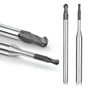
How Does Graphite End Mill Geometry Affect Tool Wear Rates?
In precision electrode production, cutting tool geometry directly dictates tool life and dimensional accuracy. We recently audited an EDM facility where switching to cutters with alternative flute profiles and edge preps doubled tool life on identical machine setups. Post-machining analysis proved the issue was not graphite hardness, but an imbalance between flute capacity, relief angles, and the abrasive nature of graphite.
Optimizing your graphite end mill geometry balances cutting load distribution, dust evacuation, and edge strength. Although graphite cuts with low mechanical resistance, its brittle fracture mechanism requires ample chip clearance to prevent secondary particle rubbing. Suboptimal tool geometry causes localized heat buildup and premature edge dulling, making specialized cutter profiles essential for high-precision molds.
The Impact of Flute Count on Graphite End Mill Wear
Selecting the proper flute count directly governs chip evacuation and cutting edge survival. We frequently see shops run four-flute tools for roughing, hoping to boost feed rates, only to experience severe dust packing and rapid edge degradation. Graphite produces high-volume abrasive dust that requires deep, open flute valleys to clear the cut zone without secondary friction.
Two-flute and three-flute geometries provide the open gullets necessary for high-efficiency roughing and deep pocketing. Four-flute configurations work best in light finishing passes where increased tool core rigidity minimizes deflection on fine ribs. Mismatching flute count with cavity volume triggers rapid graphite end mill wear, resulting in micro-chipping and lost electrode accuracy.
The Impact of Helix Angle and Chip Evacuation on Tool Life
The helix angle determines cutting force vectors, axial lift, and evacuation speed. In deep-cavity electrode work, an improper helix angle traps abrasive graphite dust along the cutter walls. The trapped powder acts as an abrasive compound, accelerating flank wear and washing out sharp corner radii.
A 30° to 35° helix angle generally delivers the best balance between cutting edge strength, smooth shearing action, and axial dust evacuation. For deep ribs or long-overhang setups, tailored helix angles minimize harmonic chatter and prevent workpiece breakout. Aligning the helix angle with cavity depth and graphite density maximizes tool stability and overall tool life.
Improving Graphite Machining Stability through Cutting Edge Geometry
Premature tool failure often traces back to cutting edge micro-geometry rather than the overall macro structure. Because graphite shears via brittle fracture, an excessively sharp, unhoned edge chips instantly under abrasive micro-impacts. Conversely, an overly heavy edge hone increases cutting pressure, causing severe push-off on delicate electrode ribs.
Optimizing positive rake angles, reinforced edge hones, and generous core thickness ensures edge stability under heavy abrasive friction. Engineered cutting edge prep dampens cutting resonance, preserves dimensional tolerances, and maintains high graphite machining stability. Designing edge geometries specifically for graphite creates predictable wear patterns and exceptional surface quality.
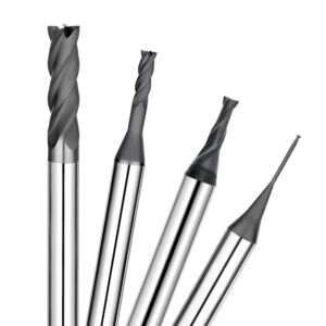
Uncoated vs Diamond-Coated Graphite End Mills: Which Offers Longer Tool Life?
Choosing the right tool coating remains a critical decision in precision electrode manufacturing. We recently consulted for an EDM shop using standard carbide tools for high-density graphite mold cores. Constant tool wear forced operators to halt production every few cycles to adjust cutter radius offsets. Telemetry showed that abrasive dust was eroding the raw carbide substrate, causing rapid diameter loss.
Selecting between uncoated and diamond-coated graphite end mills depends on production volume, graphite grade, and tolerance targets. While uncoated carbide tools can be cost-effective for prototype work or quick setups, continuous high-volume runs require higher surface hardness. Premium coatings provide the extreme abrasive resistance needed to maintain dimensional stability across complex geometries.
Advantages and Limitations of Uncoated Graphite End Mills
Uncoated micro-grain carbide tools retain a razor-sharp cutting edge with zero edge buildup. This sharpness reduces cutting forces and minimizes push-off when milling delicate electrode ribs in low-volume prototype jobs. For quick, non-abrasive, short-run setups, uncoated cutters offer an economical initial purchase price.
However, extended production cycles quickly expose the limitations of uncoated tools. Abrasive graphite dust relentlessly erodes the raw cobalt binder, rounding the cutting edge and degrading surface finish within minutes. Relying on uncoated graphite end mills for dense EDM grades spikes tool-change downtime, making total cost-per-part significantly higher than using specialized coatings.
How Do Diamond-Coated Graphite End Mills Reduce Wear?
CVD (Chemical Vapor Deposition) diamond coatings introduce a crystalline diamond barrier with hardness levels exceeding 8,000–10,000 HV. In a multi-cavity electrode project, an EDM shop struggled with frequent edge wear and constant tool offsets. Upgrading to a diamond-coated graphite end mill stabilized flank wear, held profile tolerances, and extended tool life by over 800%.
The ultra-hard diamond layer isolates the carbide substrate from abrasive micro-granules and lowers surface friction. This low coefficient of friction helps graphite dust slide out of the flutes freely, preventing localized heat buildup. Diamond coatings thrive in continuous, high-speed milling environments where holding tight electrode tolerances is critical.
The Impact of Diamond Coating on Graphite End Mill Lifespan
Evaluating tooling value requires looking at total part manufacturing costs rather than initial tool purchase prices. While diamond coating technology delivers superior wear resistance, its longevity depends on balanced feeds, speeds, and machine rigidity. Combining diamond cutters with rigid toolholders eliminates edge chipping and maximizes cutter performance.
A longer graphite end mill lifespan reduces tool-change interruptions, machine downtime, and off-spec electrode scrap. For CNC machine shops aiming to scale graphite electrode milling, pairing genuine diamond-coated tooling with optimized cutting strategies delivers reliable unattended machining and lower cost per finished part.
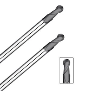
How to Extend Tool Life with Custom Graphite Milling Cutters?
Not every tool wear issue can be solved by tweaking spindle speeds and feed rates. We recently consulted for an EDM mold maker machining high-density graphite with deep, narrow rib geometry. Standard catalog end mills suffered from erratic tool life, localized chipping, and poor surface finishes because generic tool geometries could not handle the extreme reach and abrasive chip loads.
Deploying a custom graphite milling cutter tailored to your specific application solves these engineering hurdles. Machining high-density graphite demands heavy wear resistance and reinforced cores, while thin-rib electrodes require sharp shearing edges and wide flute clearance. Engineering the tool directly around your part geometry, graphite grade, and machine dynamics eliminates early failures and stabilizes production.
Designing Custom Graphite Milling Cutters Based on Graphite Material
Tool optimization starts by evaluating the specific grain structure and hardness of the graphite workpiece. Sub-micron EDM graphite causes intense abrasive friction, while coarser grades generate high volumes of powdery dust that can choke flute pockets. Using standard catalog cutters across differing grades creates wide swings in tool life and part accuracy.
When engineering custom graphite milling cutters for dense graphite, we increase core thickness and apply micro-honed edge preps to resist abrasive micro-fractures. For ultra-fine graphite grades, we adjust rake angles and flute polishing to achieve mirror surface finishes. Matching the tool’s macro and micro geometry directly to your material grade ensures predictable tool life and maximum throughput.
Tool Optimization for Various Graphite Electrode Machining Scenarios
Electrode milling operations require distinct tooling strategies across different machining stages. High-speed roughing requires maximum chip evacuation volume and impact toughness, while finishing delicate ribs demands extreme edge retention and zero tool deflection. Relying on a single end mill geometry for both roughing and finishing compromises both cycle time and tool life.
In one deep-cavity electrode project, long-reach standard tools generated severe harmonic chatter, chipping cutting edges within minutes. We re-engineered the tool with a stepped-neck relief, tapered shank, and optimized flute length to maximize static rigidity. Tailoring tool reach and neck geometry eliminated deflection, stabilized the cutting action, and tripled tool life during deep pocketing.
Customizing Tool Geometry to Improve Graphite Machining Quality
Most surface finish flaws and rib breakouts trace back to mismatched cutter geometries rather than programming errors. Flute valley depth, helix angle, and radial relief directly determine cutting force directions and chip evacuation efficiency. Aligning these geometric variables with your machine kinematics significantly dampens cutting chatter and edge chipping.
For precision EDM electrodes, fine-tuning edge preparation, flute polish, and core taper delivers superior graphite machining quality. Proper geometry control minimizes edge push-off, eliminates secondary hand-polishing, and extends cutter longevity. Investing in purpose-built tooling guarantees dependable, high-precision machining results across demanding multi-cavity mold programs.

The Relationship Between Graphite Machining Quality and Tool Wear
In precision EDM electrode manufacturing, quality defects are often blamed on material porosity or machine calibration. However, real-time machining telemetry proves that the cutting edge condition is the primary factor driving finished part accuracy. We once audited an EDM cell where initial electrode ribs were sharp and within tolerance, but extended runs produced edge chipping and dull surface reflectivity as worn cutters remained in the spindle.
Tool wear directly dictates the final graphite machining quality by shifting the material removal mechanism from clean brittle fracture to continuous rubbing and plowing. As cutting edges degrade, localized cutting forces spike, inducing sub-surface micro-fractures in the graphite. Proactive tool management must be integrated directly into your quality control system to prevent dimensional scrap before it happens.
Surface Quality Degradation Caused by Graphite End Mill Wear
Surface defects often appear before a cutter suffers complete failure. Machinists frequently report cloudy textures, inconsistent surface roughness (Ra), or subtle chatter marks despite holding identical speeds and feeds. Microscopic inspection of the cutter typically reveals that flank wear has rounded the cutting edge, destroying its clean shearing action.
As flank wear develops, the tool begins to burnish and crush the granular graphite structure rather than shearing it cleanly. In finishing passes, this abrasive burnishing elevates cutting temperatures and degrades surface integrity. Monitoring gradual graphite end mill wear through spindle load and optical presetting prevents premature surface degradation across complex EDM electrodes.
Edge Chipping, Burrs, and Dimensional Errors Caused by Tool Wear
Chipped electrode corners and out-of-tolerance rib widths are direct consequences of degraded tooling. In a recent electrode production audit, thin ribs began chipping at the exit corners after several parts. High-magnification inspection revealed microscopic nicks along the tool’s outer corner radius, causing cutting pressure to exceed the tensile strength of the graphite.
As tool wear dulls the cutting edge, radial deflection increases and forces the brittle material to break away in jagged chunks. Controlling graphite tool wear through optimized edge preps, correct chip loads, and stable toolpaths eliminates corner breakout. Protecting tool edge sharpness ensures crisp electrode profiles and holds sub-micron tolerances across long production runs.
How Can Tool Life Management Improve Graphite Machining Quality?
Predictable part quality relies on systematic tool life management rather than running cutters to complete failure. Waiting for an electrode to fail inspection before changing a tool generates costly rework and EDM downtime. Tracking dimensional trends, surface finish data, and spindle load allows shops to set proactive, wear-based tool change intervals.
A comprehensive tool management program pairs structured tool-change cycles with optimized diamond coatings, matched flute geometries, and dedicated roughing and finishing paths. This holistic approach stabilizes part-to-part consistency and elevates overall graphite machining quality. Maintaining steady cutting conditions throughout the tool’s entire service life guarantees dependable, high-precision electrode manufacturing.

Comprehensive Optimization Strategies to Extend Graphite End Mill Lifespan
Maximizing cutter longevity in precision graphite milling requires a synchronized system rather than isolated fixes. Shops often upgrade to expensive cutters or push feed rates without addressing underlying process bottlenecks, only to see premature edge degradation continue. True process stability comes from aligning tool substrate, flute geometry, vacuum dynamics, and cutting speeds with the specific graphite grade.
If your EDM operations suffer from erratic tool wear or frequent tool changes, audit the full machining chain. Check whether your axial step-downs match material density and verify that dust extraction eliminates secondary rubbing. Long-term gains in graphite end mill lifespan depend on maintaining balance between cutting forces, chip evacuation, and spindle dynamics rather than maxing out a single variable.
Optimizing Graphite Machining Parameters
Aggressive surface footage and excessive chip loads often create short-term cycle gains at the expense of severe flank wear. Forcing the cutter beyond its mechanical limits spikes localized friction and induces edge micro-chipping. Sustainable throughput requires tuning feeds, speeds, and engagement angles to maintain continuous shearing rather than abrasive rubbing.
When refining high-precision electrode workflows, adjust your spindle speed, chip load per tooth, and radial step-over in controlled increments. Prioritize tool core rigidity on micro-tools and maintain constant tool engagement via trochoidal paths during bulk roughing. Dynamically fine-tuning your graphite machining parameters based on real-time spindle load establishes a stable, repeatable cutting environment.
Selecting the Right Graphite End Mill Geometry
Cutter macro and micro geometry directly control force distribution and chip evacuation. Tools sharing identical carbide grades and coatings perform completely differently when flute counts, helix angles, or edge hones vary. High-precision electrode manufacturing demands a balanced geometry that resists harmonic deflection while clearing abrasive dust instantly.
For deep ribs and complex cavities, evaluate whether your cutter offers adequate flute capacity and core support. Two- or three-flute layouts provide essential clearance for bulk evacuation, while reinforced cores prevent deflection in deep reach zones. Matching the graphite end mill geometry directly to cavity depth and graphite grain size prevents localized wear and ensures dimensional accuracy.
Extending Tool Life with Diamond Coated Graphite End Mills
Continuous production runs on dense, fine-grained graphite accelerate abrasive wear on standard carbide edges. The abrasive friction generated during continuous dry milling strips uncoated tools quickly, causing dimensional drift on critical EDM features. Applying an engineered diamond coating creates an ultra-hard barrier that dramatically resists abrasive wear.
Evaluating tooling on a cost-per-part basis reveals the clear economic advantage of advanced diamond layers. Pairing a high-adhesion diamond coated graphite end mill with rigid toolholding delivers unattended machining stability and predictable tool life. Combining premium diamond coatings with optimized cutting parameters eliminates scrap, lowers downtime, and maximizes electrode throughput.






