



Last month, a long-standing European automotive mold client reached out with an urgent problem. They were machining UNC coarse threads into mold bodies exceeding HRC 60. Despite using premium tools, they experienced unexpected edge chipping and tool breakage after milling just three to five holes. The technical manager was frustrated, as this risked scrapping a high-value hardened mold steel block.
We have encountered this exact scenario countless times over the past 16 years while providing technical support to workshops across Europe and the US. Many experienced programmers habitually adjust spindle speed (Vc) or feed per tooth (Fz), or frequently switch carbide thread milling cutter suppliers. However, our on-site experience shows the root cause often lies in a critical, overlooked programming aspect: radial engagement strategies.
When machining large profiles like unc thread milling cutters, the extreme cutting resistance of hardened steel is exponentially amplified. Relying on standard single-pass cutting causes instantaneous, minute tool deflection. This leads to tapered threads that fail gauge inspections, causing expensive hrc65 thread milling cutters to shatter due to localized thermal stress.
Through years of tool manufacturing and process optimization, we know that well-planned multi-pass paths are the only way to extend tool life. So, is your workshop using a constant step-over approach—forcing the tool to grind directly against the hard material? Or are you employing a percentage-based incremental method to protect that fragile yet critical thread milling cutter?
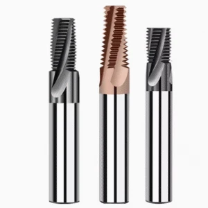
Why Single-Pass Full-Depth Cutting Destroys Your HRC65 Thread Milling Cutters
We often see seasoned machinists stumble when switching to high-hardness workpieces. They are accustomed to plunging a large-diameter tool straight to full depth, attempting to maximize efficiency through a single-pass strategy. However, when dealing with hardened mold steels rated at HRC 60 to HRC 65, this extensive radial contact forces the cutting edge to grind directly against granite-like material. The extreme frictional heat and cutting resistance instantly exceed the limits of standard coatings, leading to brittle tool fracture within just a few holes.
In our tool manufacturing test facility, we have conducted repeated comparative tests on tool life limits using various high-hardness test blocks. The results are unequivocal: when machining hard steel, tool failure is rarely caused by normal flank wear, but rather by sudden thermal cracking from instantaneous cutting force overloads. Single-pass full-depth cutting fails to provide sufficient clearance for chip evacuation and heat dissipation. This is precisely why high-performance hrc65 thread milling cutters often fail prematurely when subjected to improper tool paths.
The “Tap Mentality” Pitfall in Western Workshops and the High Cost of Broken Tools in Hardened Steel Machining
Many engineers are accustomed to traditional tapping processes, and this ingrained “tap mentality” is often incorrectly applied to thread milling operations. Traditional tapping relies on a single-pass forming process that depends on the tap’s inherent structural rigidity and torque capacity. However, expecting to cut a full thread profile in a single pass ignores the fundamental structural differences between these two machining methods. Treating a thread mill like a tap is the costliest form of toolpath laziness in a high-hardness environment.
The direct consequence of this mindset is the exorbitant cost of part rework and machine downtime. Breaking a tool in hardened steel creates a nightmare scenario where removing the fragments via electrical discharge machining (EDM) is incredibly time-consuming. We handled one disastrous case where a client attempted a single-pass thread cut on a hardened component, resulting in a scrapped aerospace-grade part worth tens of thousands of dollars. When using thread milling cutters for hardened steel, abandoning the fixation on single-pass machining is the first step toward process security.
Radial Cutting Force, Carbide Tool Deflection, and Tapered Hole Issues
From the perspective of solid mechanics, when a carbide tool cuts steel exceeding HRC 60, the outward radial cutting force increases exponentially. While solid carbide offers exceptional hardness and wear resistance, there are strict physical limits to its flexural rigidity. If the depth of cut per pass is excessive, the immense radial force pushes the tool away from the bore wall, causing minute elastic deflection in the tool body.
This deflection is particularly pronounced in deep-hole applications, creating a tapered thread profile where the threads at the bottom of the hole are too shallow. Consequently, the quality inspector’s standard Go thread gauge will fail to screw all the way to the bottom of the part. Many workshops mistakenly assume the tool is undersized and blindly adjust the tool offset, which actually compounds the error, increases chatter, and ruins the carbide thread milling cutter entirely.
Our Recommended Core Logic: Multi-Pass Machining for Hardened Steel
To thoroughly resolve the processing challenges caused by excessive radial forces, we strongly advocate for a multi-pass machining strategy. This involves systematically breaking down the total metal removal—originally intended for a single pass—into two, three, or even four separate radial passes. By controlling the radial depth of cut for each pass, we keep the radial cutting force below the deflection threshold, thereby creating a gentle cutting environment.
In practice, we favor a stepped approach comprising rough milling, semi-finish milling, and finish milling passes. The first pass handles the bulk of the material removal, while any slight tool deflection is perfectly corrected during the subsequent semi-finish and finish passes. Although this toolpath involves more machine cycles, the resulting thread profile accuracy and highly stable tool life far outweigh the costs of frequent downtime. This remains the most reliable and scientifically sound programming strategy for any high-quality thread milling cutter running in hard materials.

Radial Infeed Strategies for Thread Milling Hardened Steel—Validated in Actual Production
Threading high-hardness materials on the shop floor requires more than sound macro-programs; you must translate logic into precise toolpaths. Many operators face multi-pass cutting and plug arbitrary values into CAM software without a plan. This lack of strategy leads to highly inconsistent tool life. The root cause is a failure to match the radial path strategy to the material’s specific hardness and workpiece rigidity.
There is no “one-size-fits-all” formula for machining hardened steel. Depending on your mold steel, heat-treatment hardness, and spindle rigidity, you must make strategic choices regarding the radial path. The following infeed strategies are practical solutions we have refined and validated on-site. We have used these exact methods to help global clients successfully machine high-value, hardened components.
Constant Radial Depth of Cut Method: Stable Machining for Medium-Hardness Structural Steels
If your shop processes materials with medium hardness from 45 HRC to 50 HRC—like pre-hardened mold steels—this method is the easiest to implement. The programming logic is straightforward: the total thread depth is divided equally. For example, a 0.6 mm total depth is split into three passes with a fixed radial depth of cut (Ae) of 0.2 mm per pass. Operators can easily set these cycle parameters directly in FANUC or Siemens control systems.
However, our machining experience highlights a major physical limitation: as the tool cuts deeper, the contact area expands. Even with a constant radial increment, the cutting resistance during the final pass is significantly higher than the first. Therefore, we recommend limiting this constant step-over strategy to tougher, lower-hardness workpieces. Once material hardness exceeds 55 HRC, a fixed step-over easily triggers chatter and chips the thread milling cutter.
Constant Chip Load Strategy (Decremental Step-over): An Advanced Approach to Prevent Edge Chipping in Hardened Materials
When dealing with challenging materials like cold-work die steels hardened over 60 HRC, we strongly recommend a decremental step-over strategy. This advanced method progressively reduces the radial engagement (Ae) for each pass as the cutting depth increases. The initial pass can be deeper because only a small portion of the cutter’s edge is engaged. For the final pass, the radial depth is reduced to a minimal percentage.
This approach ensures the average chip load remains within a constant, scientifically optimal range throughout the machining process. We used this decremental logic to help high-end medical device manufacturers optimize tool life on 65 HRC materials. This precise control successfully prevents acute thermal stress caused by sudden spikes in cutting force. While the initial CAM programming requires complex calculations, it delivers remarkable predictability and stops tool breakage.
The Necessity of the “Spring Pass”: Eliminating Elastic Deformation to Pass High-Precision Thread Gauge Inspections
Regardless of your radial toolpath strategy, you should never skip a “clean-up” pass with zero radial infeed when machining hard steel. This final step is widely known among CNC engineers as a “Spring Pass.” Due to the high spring-back force of hardened steel, the tool body and spindle inevitably undergo micron-level elastic deflection. Without a spring pass, the minute amount of residual material left by this deflection remains on the thread profile.
In our technical support history, over half of the issues where “Go” gauges failed stemmed directly from skipping this final pass. Performing an additional pass at the exact same radial position completely removes the residual material caused by tool deflection. This minor programming adjustment brings the thread profile and pitch diameter tolerance to perfection. For professionals using UNC thread milling cutters, this finishing pass is a golden rule for passing gauge inspections.
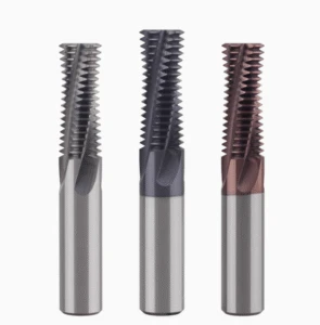
Radial Path Optimization for Large-Pitch UNC Thread Milling Cutters
Unified National Coarse (UNC) threads are standard in Western manufacturing, but machining them in hardened steel presents exponentially greater challenges. A large pitch implies a substantial geometric volume for each thread tooth. The volume of metal removed in a single pass far exceeds that of standard fine-pitch threads. Without optimizing the radial infeed path, standard carbide tools are highly susceptible to catastrophic edge failure from heavy interrupted cutting.
Having conducted numerous field tests on large-diameter fastener holes, we appreciate the need for process flexibility. Addressing large-pitch threads in heavy machinery or mold components requires more than maximizing tool rigidity. It demands smart programming that uses cutting forces to your advantage through path fine-tuning. Below, we discuss how we optimize radial paths for large-pitch UNC thread milling cutters using specific toolpath control strategies.
Challenges of Extreme Cutting Area and Vibration with UNC Thread Profiles
The distinctive thread profile angle and deep sidewalls of UNC threads cause long tool engagement lengths during 3-axis interpolation. This extreme cutting area means the tool tip must withstand intense multi-directional resistance forces with every rotation. When machining 1/2-13 UNC or larger threads in hardened steel, this large contact area inevitably triggers harmonic resonance. This chatter ruins the thread surface finish and accelerates fatigue damage to the carbide substrate.
On the shop floor, a sharp whistling sound from the spindle signals that system rigidity cannot counteract the cutting resistance. Blindly reducing the spindle speed in this situation actually causes immediate tool breakage because the chip load per tooth becomes excessive. Vibration is the primary killer of tool life when machining large-pitch threads in hard materials. The solution requires altering the angle at which the cutting edge engages the workpiece.
Reducing Cutting Resistance in Hard Steel UNC Threading via the “Modified Flank Infeed” Method
To overcome vibration issues caused by large contact areas, we frequently implement the “Modified Flank Infeed” method within CAM programming. While common in heavy-duty turning, this technique is often overlooked in thread milling applications. Its core logic involves applying a slight axial (Z-axis) offset alongside the radial infeed. This ensures the tool removes metal primarily using one side of the cutting edge, rather than subjecting both sides to simultaneous force.
We employ this modified alternating side-edge feed strategy to direct chip flow to a single side. This drastically reduces the compressive resistance at the tool tip and cuts total radial cutting forces by over 30%. Although this approach demands superior micro-segment processing from the CNC control system, it provides vital opportunities for heat dissipation. For hardened materials prone to edge chipping, this trade-off heavily extends tool life.
Achieving Smoother External Arc-in Entry via CNC Programming Fine-tuning
When machining large-pitch threads in hardened steel, the tool’s entry trajectory is just as critical as the radial infeed strategy. Many workshops rely on “straight-in” entry or standard 90-degree arc entry. While these methods work well for softer materials, they expose the tool to an immediate, full cutting load in hardened steel. This sudden impact often leads to micro-chipping at the entry point caused by thermal and mechanical shock.
We prefer using macro-programming or advanced CAM settings to implement a smooth 180-degree external arc entry with a progressive helical path. This adjustment allows the thread milling cutter to contact the hardened steel surface in a gentle, blending motion. The cutting load increases linearly from zero rather than resulting from an instantaneous shock. By enlarging the entry arc radius and switching to a tangential transition, you eliminate tooth chipping completely.
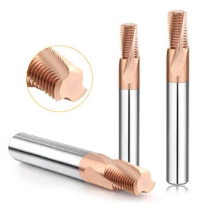
Cutting Parameters and On-Site Tuning Experience for Hardened Steel – Insights from Carbide Thread Milling Cutter Suppliers
As carbide tool manufacturers, we spend significant time alongside our technical support teams in oil-mist-filled workshops solving real-world problems. When vetting carbide thread milling cutter suppliers, many buyers focus solely on catalog specifications or unit prices. However, recommended cutting speeds and feed rates in catalogs are ideal values derived from perfect laboratory setups. Simply copying these settings to a seven-year-old machining center rarely yields good results.
Through extensive on-site tuning, we found that when machining hardened steel exceeding 55 HRC, success depends 80% on dynamic, real-time adjustments. As a premium supplier, we provide the cutting tools alongside application expertise regarding machine rigidity, spindle runout, and toolpath selection. Drawing on our core technical experience, here is how to fine-tune your cutting parameters in sync with your radial machining strategy.
A Real-World Case Study on Adjusting Feed per Tooth (Fz) Based on Radial Steps
When using a multi-pass approach in hardened steel, operators often mistakenly keep the Fz constant for every pass. We solved a classic example last quarter at a major US automotive parts manufacturer machining hardened gearbox components. While the roughing pass went smoothly, the tool emitted a harsh screeching noise during the finishing pass, leaving scratches on the thread profiles.
Because the radial depth of cut (Ae) for the final pass is minimal, a constant feed rate causes the tool to rub rather than cut. This high-heat friction causes severe localized work hardening. We recommend using a deeper radial cut with a moderate feed for roughing, then increasing the feed rate by 20% to 30% on the shallow final pass to force the edge to bite. This dynamic adjustment doubled our customer’s tool life.
Why High-Pressure Coolant Must Be Completely Disabled in Favor of Air Blast or MQL
When machining standard steel, high-pressure coolant or emulsion flooding is standard for flushing chips. However, when dealing with high-hardness materials, this approach acts as a catalyst for catastrophic tool breakage. During interrupted cutting, the temperature at the carbide cutting tip instantly spikes above 800°C. Blasting liquid coolant onto the glowing tip creates immense thermal shock, rapidly causing microscopic thermal cracks.
Therefore, when running HRC65-rated thread milling cutters on ultra-hard workpieces, our primary rule is to switch entirely to high-pressure air blast or MQL. Air blast instantly blows fine, hard chips out of the hole to prevent recutting. Allowing the tool to run dry at a stable, high temperature leverages the hot hardness of modern nanocomposite coatings, significantly extending tool life.
Assessing Radial Overload on Thread Milling Cutters by Observing Chip Color and Sound
Experienced field engineers use their eyes and ears as primary sensors to monitor the machining process. You do not need to wait for the cycle to end to gauge cutting quality; flying chips and cutting sounds tell the whole story. When using premium thread milling cutters for hardened steel, an ideal multi-pass radial cut produces a low-pitched, continuous, and rhythmic “swishing” noise.
If the sound becomes sharp and piercing, the radial load is causing severe chatter in the spindle or tool body, requiring an immediate reduction in radial depth. Next, observe the chips: under air cooling, healthy chips should be uniform dark yellow or slightly blue fine granules. If the chips turn black, smoke, or disintegrate into dust, your radial engagement is too aggressive, requiring a lower spindle speed or reduced step-over.
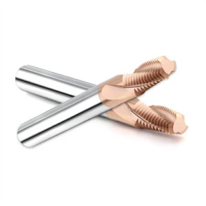
Shop-Floor Troubleshooting: Premature Thread Milling Cutter Failure Due to Improper Radial Strategies
During mass production of high-hardness parts, we always emphasize that even the best carbide substrate cannot withstand an incorrect toolpath. Often, reports of a cutter failing after threading only a few holes appear to be tool quality issues. However, if we pause the machine and analyze the macro program alongside the radial depth of cut (Ae), the root cause almost always traces back to a flawed path strategy.
Troubleshooting is about learning to let the failed cutting edge speak for itself. When dealing with extreme conditions in hardened steel, you must cross-reference shop floor realities, spindle wear, and total tool passes. Only by precisely correlating specific failure modes with radial forces can a machine shop fundamentally eliminate premature tool wear and unlock the high-performance value of their cutters.
Rapid Flank Wear: Excessively shallow radial feed causing surface rubbing
If your flank face wears flat and turns white within a short time without chipping, investigate whether your radial depth of cut is too shallow. Operators fearing tool breakage often minimize the radial depth of cut (Ae) per pass, attempting a safer approach with more passes. This leads to a major pitfall: the cutting edge fails to penetrate the material and repeatedly rubs against the hard, quenched surface.
The extreme friction-induced heat from rubbing instantly destroys the tool’s protective coating. If you notice abnormally short tool life on hardened molds, try reducing the number of passes and increasing the radial depth of cut per pass. This allows the tool tip to plunge past the hardened surface layer, replacing destructive friction with genuine cutting action. Gentle toolpaths accelerate tool dulling.
Micro-chipping: Excessive radial engagement on the first pass or an overly aggressive entry path
Acute micro-chipping along the cutting edge is an incredibly frustrating issue for CNC operators. If you observe small notches or visible fragmentation along the cutting edge, the radial engagement of your first pass was likely too deep. The engagement angle and mechanical resistance peak during the initial entry, and taking too much stock can instantly exceed the carbide’s transverse rupture strength.
If you struggle with unexpected edge chipping, review your toolpath in your CAM software. We strongly recommend reducing the radial depth of cut for the initial pass and switching from a straight plunge to a 180-degree external arc entry. Giving the cutting edge a smooth, linear transition to adapt to the load preserves the integrity of HRC65 thread milling cutters.
Thread Crest Fracture/Deformation: Chatter Caused by Mismatch Between Radial Depth of Cut and Spindle Rigidity
We occasionally encounter a phenomenon where the thread pitch diameter is within tolerance, yet the thread crests are fractured or deformed. This specific failure is rarely due to standard tool wear; it is typically caused by harmonic resonance. When machining large pitches, if the radial depth of cut exceeds the combined rigidity of the spindle and fixture, the tool undergoes violent radial oscillation.
This heavy chatter literally shatters the delicate thread crests during 3-axis helical interpolation. If you are using UNC thread milling cutters on thin-walled parts with long tool overhangs, disrupt this vibration frequency by reducing the radial depth per pass and adding spring passes. For high-hardness workpieces, cutting your radial load is the only way to ensure a flawless thread profile.





