Last month, a long-term partner workshop manager in Stuttgart, Germany, sent me a few WhatsApp photos. They showed thread mills snapped off inside the holes of precision automotive molds made of genuine HRC65 hardened steel. His message conveyed a characteristic German anxiety: “We ran the program exactly as we always have based on past experience, so why did tool life suddenly become completely unpredictable?”
We have encountered this scenario hundreds of times over the past 15 years while providing technical support to B2B clients in Europe and the US. Many CNC machinists who sail through conventional materials fall into the experience trap when facing HRC65 ultra-hard materials. Under these extreme conditions, even minor flaws are drastically magnified, leading to catastrophic tool failure within seconds.
In our years of troubleshooting for global clients, we have found that most technical literature regarding high-hardness thread milling is far too generic. Many professionals new to this field do not fully grasp the clearance advantages of 3-tooth thread mills, or they simply copy-paste standard programming logic for metric thread mills.
As thread end mill manufacturers who have spent years on the front lines of high-precision tool R&D, we know that milling threads in hardened steel requires absolute control over cutting mechanics and micro-feed toolpaths. Today, we will skip the textbook definitions and focus on the most critical operational mistakes we see in workshops around the world. I wonder if your operators are also using high-pressure liquid coolant to blast that red-hot thread milling cutter right now?

Why use 3-tooth thread end mills for aggressive machining of HRC65 hardened steel?
On the shop floor, we often see eager shop supervisors rushing to meet deadlines, trying to cut the entire thread profile in a single pass. While this blind pursuit of efficiency works for standard materials, it spells disaster when dealing with hardened steel rated at HRC65. At this level of hardness, conventional cutting rules no longer apply; the priority must shift from cutting speed to minimizing tool deflection and edge chipping under immense cutting resistance.
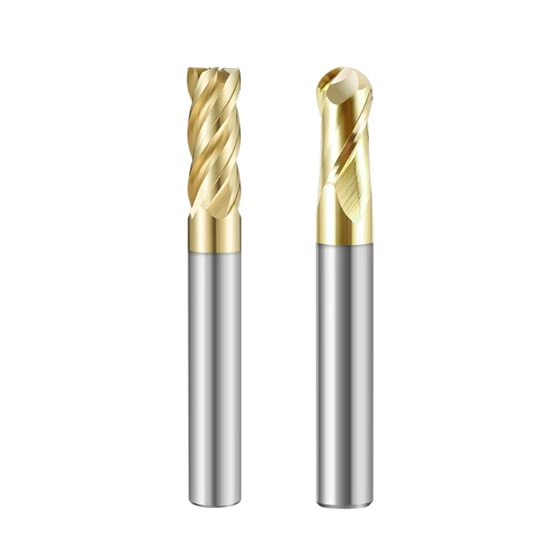
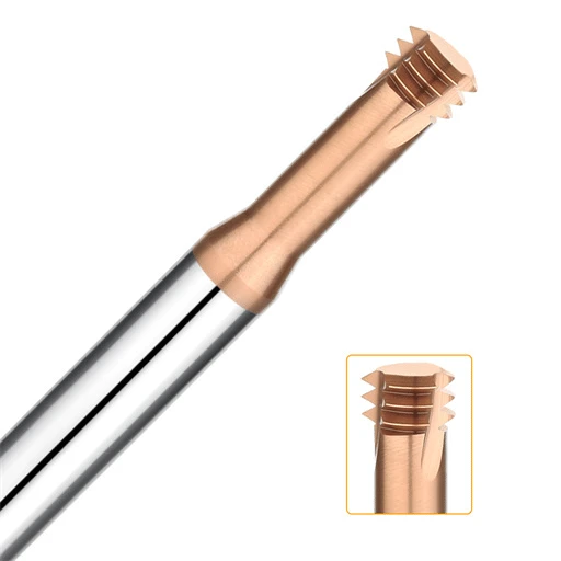
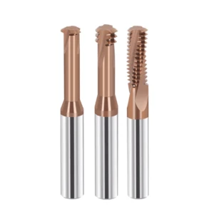
As a tool manufacturer accustomed to tackling tough materials, we know that a tool’s bending rigidity and contact area determine its survival in ultra-hard metals. That is why, when tackling deep, small-diameter threads in hard materials, we always recommend 3-tooth thread end mills to our peers. Although this design nominally sacrifices some efficiency per cycle, it strikes an optimal balance between tool rigidity and reduced spindle load.
Common Pitfall: Blindly pursuing efficiency and misusing full-profile thread mills leads to tool binding and chipping
Machinists transitioning to hardened steel often assume that a full-profile thread mill is the most efficient choice because it cuts the full thread depth in a single revolution. In practice, however, the moment a full-profile tool engages HRC65 material, all cutting teeth engage simultaneously, causing the contact area to increase exponentially. This spikes spindle torque, causes instantaneous tool deflection, and results in a sharp snap inside the hole.
We must acknowledge that a single-pass approach is completely unfeasible when utilizing thread mills for hardened steel. Full-profile tools encounter massive cutting resistance, and the narrow spaces between the teeth leave virtually no room for chip evacuation. If these tiny, hard chips are not cleared promptly, they undergo secondary cutting within the hole, generating instantaneous temperatures exceeding 1,000°C that ruin tool coatings.
Real-World Case Study: Why we advised a European/American client to switch from multi-tooth cutters to 3-tooth thread end mills when machining mold steel
Late last year, a mold manufacturing plant in Ohio, USA, encountered serious difficulties while machining heat-treated SKD11 mold steel with a hardness of HRC62–65. In pursuit of higher productivity, they insisted on using traditional full-length multi-tooth thread mills. Within half a day, they had scrapped over a dozen expensive imported cutters and nearly ruined a mold assembly worth tens of thousands of dollars.
After their technical lead contacted us, our primary recommendation was to immediately switch to 3-tooth thread end mills and shift to multi-pass machining. Although the machining cycle time appeared longer, the 3-tooth design significantly reduced the instantaneous contact length between the tool and the hardened steel. This eliminated the tool breakage nightmare and actually allowed them to complete final delivery three days ahead of schedule.
On-Site Analysis: The Physics Behind Reduced Cutting Resistance with 3-Flute Thread Mills in High-Hardness Machining
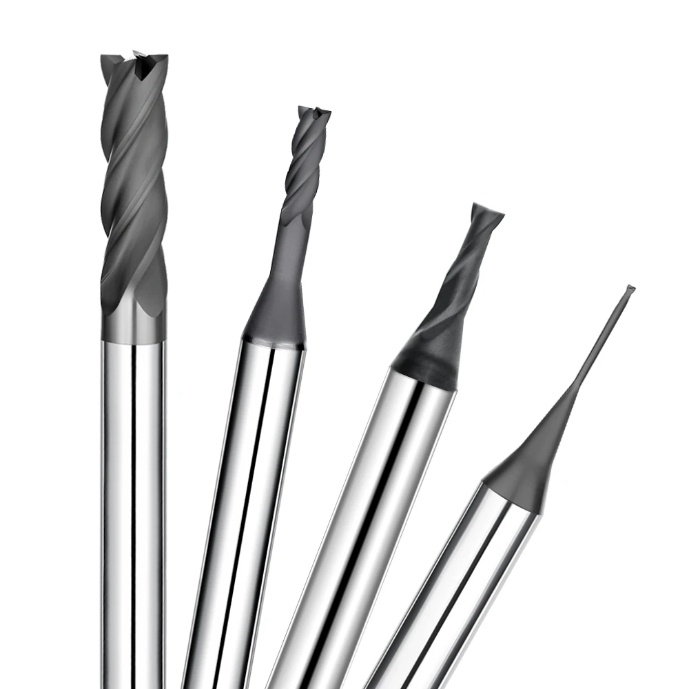
From the perspective of cutting mechanics, troubleshooting shop-floor issues requires balancing the metal removal rate against the rigidity of the tool overhang. When machining with specialized hrc65 thread end mills, the 3-flute design offers a significant structural advantage in chip clearance and vibration damping. Because only three flutes engage, the point of force application during helical interpolation is tightly confined, minimizing radial cutting forces.
Furthermore, the 3-flute configuration provides ample space for chip evacuation flutes. During high-speed CNC rotation combined with powerful air blast, the fine, needle-like chips characteristic of hardened materials are ejected cleanly from the hole. These physical characteristics allow the cutting edge to maintain a relatively stable temperature profile, preventing thermal fatigue and edge chipping under extreme operating conditions.
Blind Spots in Selecting Metric Thread Mills
Milling metric threads in blind holes is a high-risk operation on the shop floor, especially when dealing with hardened workpieces. When planning toolpaths, process engineers often focus solely on thread specifications while overlooking the physical clearance between the tool neck and the uncut hole wall. This tight space means even a minor calculation error can trigger severe mechanical interference at the bottom of a narrow hole, causing a catastrophic tool crash.
During on-site audits for global clients, we found that success in machining blind holes hinges largely on the ratio between the pilot hole and the tool’s outer diameter. Consequently, when selecting metric thread mills, you must balance chip clearance space and tool body rigidity equally. Prioritizing shank rigidity at the expense of chip evacuation channels—or opting for an overly slender neck—will lead to disastrous tool failure under immense reactive forces.
Common Pitfall: Blindly Adopting Standard Pilot Hole Charts (D1/D2 Ratio Mismatch)
A frequent error in many small-to-medium-sized workshops across Europe and the US occurs right before machining metric threads in hardened steel. Operators habitually consult standard pilot hole charts designed for ordinary steel, which are intended for conventional tapping and specify high thread height percentages. However, if the pilot hole is drilled too small in HRC65 steel, the tool is forced to remove a thicker layer of metal, causing cutting resistance to rise exponentially.
Hardened steel exhibits virtually no plastic deformation during machining, relying instead on brittle chip fracture. Adopting conventional pilot hole dimensions leaves insufficient clearance for safe tool retraction between the theoretical minor diameter (D1) and the mill’s actual cutting diameter (D2). During interpolation, the non-cutting sections of the tool are highly prone to side friction, creating a silent killer that leads to premature edge wear on metric thread mills.
Customer Pain Point: Tool breakage due to torque spikes caused by insufficient chip evacuation space when machining small-diameter metric threads
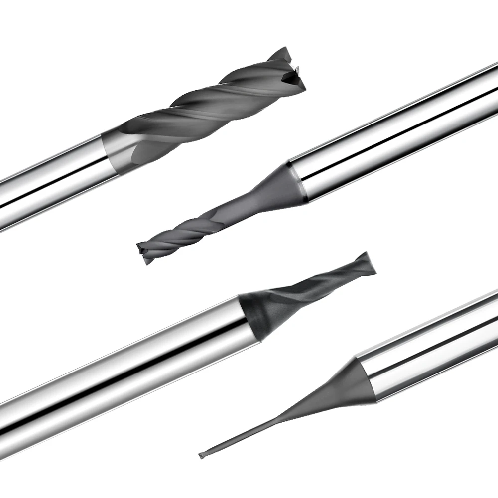
When scaling down to small thread sizes like M3 or M4, the margin for error in hardened blind holes drops to near zero. Our medical device clients in the UK and Canada frequently report that small-diameter metric thread mills snap at the bottom of the hole just seconds into the cut. The tool fails before the machine’s torque alarm can even trigger, and clearing carbide debris from these tiny holes brings workshop productivity to a complete standstill.
On-site troubleshooting reveals that the root cause is rarely tool quality, but rather the extremely challenging chip evacuation environment. Pilot holes for small-diameter threads are inherently deep and narrow, allowing fine, granular chips to accumulate at the base. As the cutter spins at high speed within this confined space, trapped chips get crushed between the tool flutes and the hole wall, creating a massive torque spike that easily breaks the micro-tool shank.
Solution: Correction parameters and tool offset recommendations for hardened steel pilot holes from thread end mill manufacturers
Facing these machining dead zones characterized by tight spaces, we—as thread end mill manufacturers—offer clients an unconventional correction strategy. First, when machining materials exceeding HRC60, we recommend slightly enlarging the pilot hole diameter by 0.05mm to 0.1mm while still ensuring the thread passes gauge inspection. This minor adjustment creates valuable chip clearance space and significantly reduces the cutting load during the initial entry pass.
Furthermore, to address the elastic recovery and tool deflection associated with hardened steel, we no longer rely on operators to manually fine-tune the machine’s D-value compensation by intuition. Instead, we incorporate radial passes and spring passes directly into the programming stage. Making multiple incremental passes to approach the final profile—and concluding with a zero-infeed spring pass—effectively corrects out-of-roundness and pitch diameter taper caused by tool deflection.
The Fatal Entry Path: Why Do Your Thread Mills for Hardened Steel Always Break at the Start?
When troubleshooting machining issues, we often observe a classic phenomenon: many thread mills do not fail due to gradual wear during the milling process. Instead, they snap with a sharp, audible crack within the first few seconds of contacting the workpiece. This failure-at-the-start scenario can almost always be traced back to the design of the toolpath, as an aggressive entry path acts as an immediate death warrant in ultra-hard materials.
As engineers dedicated to precision hole machining, we know that the initial contact phase is the most critical moment when working with parts exceeding HRC60 hardness. We must ensure that the load experienced by the tool during entry builds up gradually rather than spiking instantly. If the programming fails to account for the machine’s corner deceleration characteristics, even the most expensive thread mills for hardened steel will likely snap at the very first step.
Common Pitfalls: Straight Radial Entry or Incorrect 90° Entry Paths
In routine machining, operators often choose the default straight radial entry or a 90° right-angle entry path in their CAM software simply for convenience. With this type of toolpath, the cutter positions itself at the center of the hole and then moves in a straight line, slamming directly into the hole wall. Under these conditions, the depth of cut surges from zero to its maximum value in a fraction of a millisecond, subjecting the cutting edge to an immense impact force.
Through countless simulations and practical tests, we have observed that this unbuffered entry path causes severe instantaneous deflection at the tool’s overhang. Even worse, a 90° entry forces the first cutting tooth into a state of brute-force engagement before a stable dynamic balance of cutting resistance can be established. This sudden, violent lateral vibration instantly compromises the tool’s micro-edge, causing the coating to flake off immediately before the tool snaps.
Engineer’s Note: Practical G-code Modification for 180° Arc-In Feeding When Machining 65HRC Hardened Steel
When optimizing programs for our precision aerospace component clients, our first mandatory instruction is the use of a smooth 180° arc entry. This trajectory allows hrc65 thread end mills to gradually approach the final cutting depth along a gentle semi-circular arc. During this process, the width of cut increases along a progressive curve, while the machine spindle torque and primary cutting force rise steadily and linearly, providing the tool body with sufficient time to maintain rigidity.
When providing on-site technical support, we often manually modify the interpolation segments in the G-code. We discard the rough entry paths automatically generated by CAM software in favor of coordinated G02 or G03 commands utilizing I and J vector control. We position the entry point further away from the final cutting path and assign a dedicated, lower feed rate to this 180° arc segment, typically 40% of the standard cutting feed rate.
Dynamic Load Analysis: Mitigating the Impact of Initial Cutting Engagement—A Decisive Factor in Extending the Service Life of Thread Mills for Hardened Steel
From the perspective of stress transmission physics, tool life when machining hardened steel depends heavily on the stability of the contact mechanics structure. During high-speed interpolation, the cutting teeth undergo thousands of intermittent engagement and disengagement cycles within the hole. If the entry path lacks smoothness, each contact generates a high-frequency shockwave that rapidly propagates along the cutting edge to the tool shank, causing premature fatigue damage.
Conversely, by optimizing the toolpath to minimize localized impact forces during entry, the tool’s sub-micron, ultra-fine-grained carbide substrate can fully utilize its inherent compressive strength. Simultaneously, the nano-scale coating establishes an effective thermal barrier under relatively stable temperature and friction conditions. Comparative data demonstrates that simply optimizing the dynamic load of the entry path consistently extends the average service life of thread mills for hardened steel by more than 60%.

Misguided Cooling Strategies: Should HRC65 Thread End Mills Use Emulsion or High-Pressure Air Cooling?
In daily CNC workshop operations, many machinists instinctively crank the coolant pump to the maximum when they see sparks flying. Flooding the workpiece with cutting fluid makes perfect sense for aluminum or ordinary carbon steel, but it often proves fatal when dealing with hardened steel rated at HRC65. The key to temperature control when machining ultra-hard materials is not merely lowering the temperature, but maintaining absolute thermal stability.
Our extensive on-site technical support has revealed that the frictional heat generated under immense cutting resistance is staggering. Incorrect cooling strategies disrupt the physical and mechanical balance of the tool’s surface rather than protecting it. Scientifically managing the thermal dynamics in the machining zone for precision tools like hrc65 thread end mills is just as critical as setting the cutting parameters themselves.
The Misconception: Habitually Activating High-Pressure Liquid Cooling Upon Seeing High Temperatures
Conventional wisdom holds that water-based emulsion is the best choice for dissipating heat and preventing thermal softening. However, when a thread end mill performs high-speed helical interpolation inside HRC65 hardened steel, the tiny contact area causes the cutting zone to instantly exceed 1,000°C. Blasting high-pressure emulsion directly onto the rapidly rotating cutting edge creates a dangerous thermal gradient barrier around the periphery.
The immediate consequence of this practice is that the tool tip is subjected to rapid, extreme fluctuations between scorching heat and biting cold. Sub-micron grade carbide substrates are extremely vulnerable to such unstable thermal environments. The habitual use of liquid coolant fails to evacuate tiny chips from the bottom of the hole, triggering microscopic-level thermal shock that causes hrc65 thread end mills to fail prematurely.
Workshop Disaster: How Thermal Shock Instantly Ruined a High-Value HRC65 Thread End Mill
The summer before last, a German-owned automotive parts supplier in Kunshan encountered a baffling tool life bottleneck. While using specialized cutters to machine fine-pitch metric threads on high-hardness gear shafts, tool life was wildly inconsistent. Sometimes they could machine dozens of parts, while at other times, an entire tooth would suddenly chip off after completing just two holes, leading the supervisor to suspect a bad tool batch.
This was a classic case of brittle fracture caused by material fatigue from thermal shock. During helical interpolation, each cutting tooth endures temperatures exceeding 1,000°C when entering the hard steel, only to be abruptly cooled by icy emulsion upon exiting. This high-frequency cycle causes countless microscopic thermal cracks to form instantly in the nano-coating of hrc65 thread end mills, leading to catastrophic breakage without warning.
Best Practice: Why Air Blast Is the Only Correct Solution for Thread Milling High-Hardness Steel
Based on our R&D as thread end mill manufacturers, a powerful dry air blast combined with Minimum Quantity Lubrication (MQL) is the optimal solution for threading hardened steel. MQL systems atomize minute amounts of vegetable-based lubricant into micron-sized particles, delivering them via compressed air precisely to the cutting zone. This ensures essential boundary lubrication while avoiding the thermal shock caused by sudden temperature drops.
In this near-dry environment, a significant portion of the cutting heat is absorbed by the fine, needle-like chips and rapidly expelled by the air blast. Maintaining a stable, consistently high temperature in the cutting zone actually promotes localized thermal softening of the ultra-hard material, reducing cutting forces. Long-term data from independent workshops proves that embracing dry air cooling is the only way to achieve predictable tool life.

Neglecting Machine and Tool Holder Rigidity: Tool Life Lost to Micro-Chatter
On the shop floor, we often encounter machinists who invest heavily in premium cutters, yet still experience erratic, roller-coaster-like tool life. The answer often lies in their tool-clamping methods rather than the cutter itself. When machining materials around HRC65, the rigidity bottleneck of the entire system rarely lies with the tool, but rather at the connection points between the tool holder and the machine spindle.
High-hardness machining is incredibly sensitive to micro-chatter. Under high cutting forces, even the slightest resonance from insufficient clamping force or radial runout transforms into high-frequency micro-hammering impacts directly striking the fragile carbide cutting edge. Consequently, when planning processes for thread mills for hardened steel, our team invests significant effort in scrutinizing the rigidity of the entire workholding setup.
A Common Pitfall: Using Standard ER Collets or Even Heavy-Duty Milling Chucks for Hardened Steel Thread Mills
For convenience, many machine shops habitually insert hardened steel thread mills directly into existing ER collet chucks. This approach fails completely when dealing with hardened steel exceeding 60 HRC, because standard clamping forces cannot withstand the intense lateral cutting resistance. Due to structural limitations, collet segments undergo slight elastic deformation under extreme loads, leading directly to uncontrollable radial runout during high-speed rotation.
Our production tests reveal that while heavy-duty milling chucks offer better grip, their bulky nut structures generate substantial centrifugal inertia during high-speed helical interpolation, often triggering resonance. Regardless of the standard chuck type used, once radial runout exceeds 0.005 mm, a tool will experience unilateral tooth overloading within the hole. This makes edge chipping inevitable for any 3-tooth thread end mills or multi-flute cutters.
On-Site Strategy: Why We Mandate the Use of Shrink-Fit or Hydraulic Chucks for Our Western Clients
Last year, while supporting a UK precision engineering firm that supplies components to Boeing, we encountered a persistent issue regarding thread consistency. Our technical solution was mandatory: they had to completely phase out standard chucks in favor of shrink-fit or high-precision hydraulic chucks. Many engineers accustomed to traditional clamping methods were initially hesitant, but their doubts vanished once they witnessed the runout data on a dynamic balancing machine.
Shrink-fit holders utilize thermal expansion and contraction to achieve a secure, 360-degree circumferential grip, limiting radial runout to within 0.003 mm. Meanwhile, high-quality hydraulic holders absorb high-frequency micro-vibrations via an internal hydraulic chamber. When switching to this high-rigidity clamping method combined with our 3-tooth thread end mills, the workshop’s harsh screech gave way to a smooth cutting sound, and tool life doubled consistently.
Managing Overhang Rigidity: Eliminating Hole-Mouth Taper in High-Hardness Thread Machining by Controlling the Length-to-Diameter Ratio
Beyond the choice of tool holder, tool overhang is another critical factor affecting rigidity that is often overlooked. When machining metric threads in deep blind holes, many operators leave excessive tool overhang, reasoning that “as long as it reaches the bottom, it’s fine.” However, tool deflection under load is proportional to the cube of the overhang length, meaning that every additional 5 mm of overhang increases elastic deflection exponentially.
When assisting clients in troubleshooting threads failing gauge tests due to hole-mouth taper, our primary solution is strict management of the length-to-diameter ratio. For small-diameter metric thread mills, we advise against an effective overhang exceeding three times the cutting diameter. Controlling the physical deflection of the tool tip at the micron level is the fundamental assurance for ensuring that hardened steel threads pass gauge inspections on the first attempt.
A Guide to Avoiding Pitfalls: How to Identify High-Quality Thread End Mills for Hardened Steel?
Having discussed common operational errors and shop-floor configurations, we must ultimately return to the tools themselves. On the desks of many shop supervisors, you will find blueprints from a dozen different suppliers that appear virtually identical in terms of basic geometric parameters. However, as industry peers who have spent over a decade in tool R&D, we know the true technological moat for carbide tools used on HRC65 hardened steel lies in microscopic details invisible to the naked eye.
If you are plagued by inconsistent tool life or baffling instances where a brand-new tool suffers sudden edge chipping without warning, look beyond mere price. Re-evaluate your current setup by considering the manufacturing source and the fundamental logic of the supply chain. Specializing in high-precision hole machining, we understand that a sharp weapon capable of tackling ultra-hard materials requires meeting rigorous physical specifications—from base material selection to final micro-honing of the cutting edge.
The Pitfall: Choosing Cheap, General-Purpose Thread Mills Based Solely on Identical Blueprint Geometries
In large independent workshops across Europe and the US, purchasing and technical departments often clash over tooling costs. Purchasing staff frequently fall into a trap: if the thread profile angle, pitch, and flute length of two metric thread mills are identical on paper, they choose the cheaper general-purpose option. However, general-purpose tools are designed to balance performance across low-to-medium hardness materials like standard steel, cast iron, and aluminum.
When these cheap, general-purpose tools engage with hardened steel exceeding 60 HRC, their cutting edges lack the necessary rigidity, leading to instantaneous chipping under immense cutting resistance. Furthermore, their flute finish falls far short of the standards required for hardened steel, meaning needle-like chips struggle to slide out smoothly. This easily leads to chip jamming and sudden tool breakage. Geometric dimensions on a blueprint are merely the surface; general-purpose tools simply cannot replicate the specialized clearance geometries needed for hard metals.
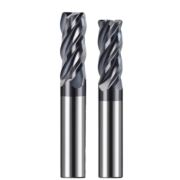
Manufacturing Insights: Specialized Processes for Substrate Grain Size and Nano-coatings in HRC65-Grade Thread End Mills
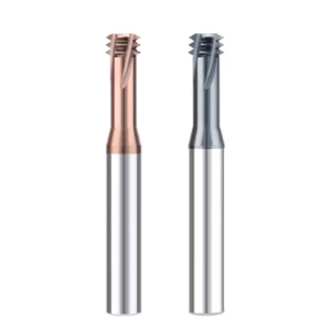
As tool manufacturers dedicated to pushing the limits of material performance, we want to share some insider details regarding the production of these premium tools. When producing specialized hrc65 thread end mills, we never use the standard carbide grades found on the commodity market. Instead, we select sub-micron or nano-scale ultra-fine grain rod stock with grain sizes between 0.2 and 0.4 microns.
This premium substrate provides exceptional hardness while delivering the impact toughness crucial for withstanding the interrupted cutting conditions typical of hardened steel machining. Regarding coatings, standard TiAlN films oxidize and flake off rapidly under the extreme heat generated above 60 HRC. As reliable thread end mill manufacturers, we utilize high-precision coating equipment to deposit specialized composite nano-structured coatings like AlTiN/SiN, which withstand instantaneous temperatures up to 1,100°C.
Final Inspection Standards: How European and American Engineers Assess the Potential of Tools for Machining Hardened Steel Based on Edge Preparation Quality
In our extensive technical support experience, we often advise process engineers in Europe and the US not to rush to mount new tools immediately upon receipt. Instead, they should first examine the cutting edge under a microscope with at least 100x magnification. For tools specifically designed for hard steel, a razor-sharp edge is actually a liability; it will suffer microscopic chipping the instant it engages with 65 HRC material.
The core expertise of premium manufacturers lies in the pre-delivery edge preparation, or micro-honing, process. We use precision suspension grinding or drag finishing to refine the cutting edge into a smooth arc with a radius of just a few microns. If you are using premium 3-tooth thread end mills to machine precision aerospace components or high-value molds, you can easily gauge a tool’s potential by observing the uniformity of the light reflection along this micro-honed edge.