


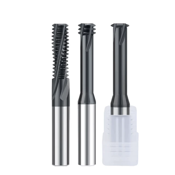
Last week, our team helped an Ohio precision shop solve a nightmare job. Their supervisor called frantically: while machining 316L stainless steel medical fittings, thread mills rated for 50 holes were snapping after just three. These broken tools threatened to scrap a massive batch of high-value parts.
For our team, with 16 years in carbide tool R&D, this was a classic case. We went on-site and opened the enclosure to inspect the chips with their programming director. The problem was instantly clear: they had copied cutting parameters meant for through-holes and applied them directly to blind holes.
Stainless steel—whether common 304/316 or tough duplex—is notorious for its stickiness and work-hardening tendencies. In production, blind and through-holes demand completely different strategies for chip clearance, coolant delivery, and radial cutting forces.
Supplying wholesale thread mills and technical support worldwide has shown us how often shops confuse these two hole types. This common oversight leads to chipped edges on expensive tools or out-of-spec, tapered threads.
Using thread mills for stainless steel cuts machining forces to just 5% of traditional tapping. However, running stable, unattended mass production requires distinct process strategies based on how the hole is drilled.
When cutting blind holes, you must use short-flute or single-tooth cutters to evacuate chips and prevent recutting. For through-holes, the goal is maximizing full-flute efficiency while controlling tool deflection caused by long overhangs.
These are not textbook theories; they are hard-won lessons bought with hundreds of broken tools and endless G-code adjustments. Since you battle austenitic materials daily, ask yourself: have you really allowed enough pilot hole depth clearance in your shop?

Blind Hole Machining: Why We Recommend Single Tooth or Short Flute Thread Mills for Stainless Steel
Threading blind holes in materials like 304 or 316 stainless steel is a notorious shop-floor bottleneck due to poor thermal conductivity. The confined space at the bottom easily becomes a graveyard for cutting tools. Over the past decade, we have optimized deep-hole processes for dozens of clients, leading to one proven consensus: attempting to cut blind-hole stainless threads in a single pass with a full-profile tool is a recipe for high scrap rates.
To drop cutting forces and guarantee clear chip evacuation paths, we prefer recommending single-tooth or short-flute thread mills for stainless steel. While this geometry requires more helical interpolation passes, the minimal workpiece contact minimizes radial force and localized heat buildup. For any process engineer struggling with sticky stainless blind holes, sacrificing a few seconds of cycle time for 100% machining reliability is a no-brainer trade-off.
The Battle for Chip Clearance: The Fatal “Re-engagement” with Chips at the Bottom of Blind Holes
Stainless steel produces long, sticky, continuous ribbon chips rather than brittle, self-breaking fractions. While through-holes allow gravity and coolant to flush chips straight out, blind holes offer no escape route, causing chips to nest at the bottom. If your stainless steel thread cutter packs into this confined area, it will grind directly against work-hardened scrap, causing instantaneous and catastrophic edge chipping.
Many machinists blindly drop the feed per tooth to improve surface finish, but this creates light, bird-nest chips that wrap around the tool. This fatal chip re-engagement destroys pitch diameter tolerances and snaps solid carbide tools inside the hole. When programming blind holes, always prioritize evacuation over speed by reserving a bottom clearance of at least 1.5 to 2 times the thread pitch as a dedicated chip reservoir.
Why Are Thread Cutters with Large Relief Angles Better Suited for 304/316 Blind Holes?
Many buyers focus strictly on tool diameter and coatings, overlooking how cutting edge geometry interacts with a material’s yield strength. Austenitic stainless steel exhibits intense “elastic recovery,” meaning the material springs back immediately after the tooth passes, tightly gripping the tool body. If your thread cutter tool uses standard relief angles, the flank face rubs heavily against the hole wall, causing severe friction, screaming vibration, and instant surface hardening.
To counter this, we engineered an optimized design featuring a large relief angle paired with extra-wide chip flutes for blind-hole applications. The increased relief eliminates flank rubbing and heat buildup, while the deep flutes act like shovels to guide sticky chips upward. While a larger relief angle slightly reduces tool tip backing rigidity, our field data on 304 and 316 proves this minor trade-off yields effortless entry and drastically extended tool life.
Our Recommended Strategy for Blind Hole Chip Evacuation: Combining High-Pressure Through-Spindle Coolant (TSC) with Strategic G-Code Programming
If your CNC machine features TSC exceeding 70 bar (1000 PSI), you are already halfway to mastering stainless blind holes. External flood coolant cannot penetrate deep holes effectively, often washing chips back inside rather than out. We always advise using metric thread mills engineered with internal coolant channels, allowing high-pressure fluid to blast directly from the tip and force chips up the helical flutes.
On standard machines lacking TSC capabilities, you must rely on strategic, customized G-code programming to prevent tool failure. We strongly advise against a single, uninterrupted plunge; instead, deploy a multi-pass approach using macro programs with a slight dwell or stepped retraction sequence. Command the tool to step up along the Z-axis after one or two interpolation loops to pull chips out before resuming. This method safely guarantees clean metric tolerances without high-end hardware.
Through-Hole Machining: How to Maximize Stainless Steel Machining Efficiency with Multi-Tooth Metric Thread Mills?
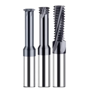
With nerve-wracking blind holes covered, let’s talk through-holes. Here, gravity and coolant naturally flush chips out the open bottom, instantly easing the cutting environment. When partnering with Western automotive or flange OEMs on through-hole parts, we swap conservative single-tooth tools for high-efficiency metric thread mills to aggressively slash cycle times.
These multi-tooth powerhouses often feature a cutting length that spans the entire workpiece thickness. This lets the spindle form the complete thread profile in just one 360-degree helical interpolation pass. However, as tool manufacturers, we must remind peers that higher efficiency scales up cutting resistance, requiring a smart balance between metal removal rates and machine rigidity.
The Natural Advantage of Through-Holes: Enabling High-Efficiency, Single-Pass Machining with Full-Length Metric Thread Mills
Through-holes inherently eliminate the nightmare of chip packing. When running a 15mm-thick 304 stainless steel flange with full-length metric thread mills, you can ditch the cautious, incremental multi-pass strategies required for blind holes. The tool extends straight through the bore, completing the thread in one smooth interpolation loop and reducing cycle times by over 60%.
However, operators must not mistake a clear exit for an excuse to run blind parameters. Engaging the full flute length simultaneously spikes radial cutting forces, demanding heavy torque from your machine spindle. On lightweight machining centers, this sudden load triggers severe chatter, meaning you should use your CAM software to split the path into radial multi-passes for heavy pitches.
Managing Overhang and Rigidity: Preventing Tool Deflection in Long Through-Hole Threading
Machining thick plates or deep through-holes invariably introduces high length-to-diameter ratios. Once tool overhang exceeds three times the diameter, any thread cutter tool will suffer elastic deformation—known as tool deflection—against tough, high-hardness stainless steel. This deflection leaves you with a tapered thread that jams your “Go” plug gauge halfway through inspection.
Fixing deep-hole deflection tests a tooling engineer’s true practical judgment. We typically advise clients to first choose solid carbide cutters with short, rigid shanks while minimizing the stick-out from the collet. Second, we apply taper compensation in the G-code, slightly increasing the interpolation radius at the bottom to offset the deflection error dynamically.
The Real Impact of Climb Milling on Reducing Tool Wear in Stainless Steel Through-Hole Machining
Your choice of cutting direction directly dictates whether your tooling survives or dies on the shop floor. For highly work-hardening materials like austenitic stainless, we strictly mandate climb milling for all through-hole setups. Climb milling transitions from a thick chip to a thin one, allowing the stainless steel thread cutter to clear chips instantly and avoid rubbing the hardened surface.
Conversely, conventional milling forces the tool tip to rub and slide violently against the stainless steel before biting in. This friction spikes local temperatures, immediate work-hardening the surface so subsequent teeth are essentially cutting hardened tool steel. For the rigid, linear-guide CNC machines common in modern Western shops, climb milling is the undisputed choice for maximizing tool life.

Blind Holes vs Through-Holes: Differentiated Strategies for Toolpath Programming (G-Code)
Selecting the right tool is only half the battle; flawless stainless threads require customized CNC programming. Many process engineers underestimate how toolpath mechanics affect tool life, running identical macro programs for both hole types until a catastrophic tool failure sounds the machine alarm. Our 16 years of technical field support have proven that blind and through-holes require completely different G-code logics.
While through-hole programming focuses on seamless continuity and fast exit speeds, blind holes demand error-prevention tolerances baked into every block of code. Customizing your interpolation paths creates a safe clearance zone for expensive thread mills for stainless steel. This strategic programming mitigates immense radial material resistance and stops edge chipping right at the source.
Safety Clearance at the Bottom of Blind Holes: Programmatic Protection to Prevent Bottoming Out
The most nerve-wracking moment in blind-hole programming is the rapid Z-axis plunge to the initial cutting depth. Because pilot holes drilled in stainless steel leave a conical tip, programming your thread endpoint too deep invites disaster. Any slight spindle thermal expansion or part fixture shift will cause the rotating stainless steel thread cutter to crash into that angled floor, shattering the carbide tip instantly.
To build a foolproof safeguard, we train our clients to master the concept of programmatic clearance. Our shop standard requires retracting the G02/G03 helical interpolation start point at least 1.5 times the thread pitch above the drill point. Additionally, programmers must use a smooth arc lead-in and lead-out path rather than a straight G01 radial plunge to soften the tool engagement.
Bottom-Up or Top-Down? A Comparison Based on Our Shop-Floor Tests
Workshops frequently debate the ideal path direction for stainless thread milling: cutting from the top down versus positioning at the bottom and pulling upward. We conducted months of on-machine testing with 316 stainless steel in our pilot facility to settle this. The data revealed a sharp performance split between how these paths interact with the tool.
Top-down toolpaths work beautifully for through-holes because gravity assists chip fall. However, for blind holes, we highly recommend a bottom-up programming approach using a specialized thread cutter tool. Spiraling upward from the bottom naturally lifts the sticky ribbons out of the hole, significantly cutting down on the risk of chip recutting and localized heat packing.
Case Study – Multi-pass Machining of Blind Holes in Difficult-to-Machine Duplex Stainless Steel
Machining duplex stainless steel (like Duplex 2205) or precipitation-hardening alloys (like 17-4PH) doubles your difficulty compared to standard 304. These materials exhibit extreme yield strength, meaning a single-pass strategy creates massive radial forces that deflect long-reach metric thread mills and tear threads. Last year, we solved this exact problem for a Norwegian offshore equipment manufacturer whose duplex blind holes tore regardless of speed.
Our solution completely abandoned single-pass interpolation, replacing it with a refined three-pass G-code strategy: roughing, semi-finishing, and finishing. The rough pass removed 70% of the material, evacuating the bulk of the cutting heat and work-hardened layer. The final pass ran as a zero-feed spring pass to eliminate tool deflection, allowing the client to consistently pass high-precision thread plug gauges.
The Western Buyer’s Perspective: Optimizing “Cost-Per-Hole” in the Workshop through Wholesale Thread Mill Procurement
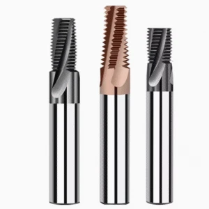
Over a decade of working with Western B2B procurement managers has shown us an interesting trend: top professionals never look at just the initial tool price. Instead, they ruthlessly calculate the project’s overall cost-per-hole. In high-stakes stainless steel setups, the downtime and scrapped parts from cheap, unpredictable cutters cost far more than premium tooling. As an original manufacturer, we always advise volume buyers to optimize their tooling spend directly at the supply chain source.
Strategic sourcing through wholesale thread mills does more than just unlock bulk discounts; it builds a highly predictable, risk-resilient tooling protocol. If your shop is burning through tooling budgets or missing shipping deadlines due to stubborn alloys, you need to re-evaluate your inventory classification. Matching your bulk orders to your actual workshop floor data is the fastest way to uncover massive, hidden cost-per-hole savings.
Why We Recommend Distinguishing Between Blind and Through-Hole Inventory When Buying Thread Mills in Bulk
Some procurement managers order one general-purpose tool model in bulk, expecting the shop floor to run it on both blind and through-holes. While this simplifies warehousing, it destroys profitability on the actual production line. As we analyzed earlier, blind and through-holes have completely different physics regarding chip packing, radial deflection, and G-code exit paths. Forcing a full-flute through-hole cutter into a tight stainless blind hole triggers rapid edge chipping.
If you are consuming tools in large volumes, break down the exact ratio of blind to through-holes in your stainless steel part runs. We highly recommend separating your purchase orders into blind-hole tools (single-tooth or short-flute) and through-hole tools (high-rigidity, multi-tooth designs). This minor change in inventory management ensures every thread cutter tool operates in its ideal cutting environment, yielding an exponential leap in total tool life.
Consistency of Coating and Substrate: A Critical Metric for Evaluating Bulk Thread Mill Quality
The ultimate nightmare for any bulk buyer is a shipment where the first five tools run beautifully, but the next ten fail randomly. Stainless steel is completely unforgiving; a slight grain shift in the carbide substrate or a few microns of deviation in the AlTiN coating ruins tool life. When evaluating a supplier for a high-volume stainless steel thread cutter contract, batch-to-batch consistency is the single most critical metric to verify.
Before signing a long-term supply agreement, always demand certified substrate documentation and automated coating thickness verification reports. In our factory, we run every single bulk batch through rigorous, automated inspections on high-end Walter and Zoller micro-measuring machines. Ensuring identical edge honing, substrate hardness, and coating adhesion across the entire shipment is the only way your shop can safely run automated, lights-out production.
Insights from a 16-Year Manufacturer: Reducing Overall Tool Consumption for Western B2B Clients through Custom Non-Standard Length-to-Diameter Ratios
Standard tool catalogs offer rigid, general-purpose length-to-diameter ratios that often struggle in niche, high-spec industrial applications. In demanding sectors like aerospace or oil and gas valve manufacturing, standard lengths introduce severe tool deflection from excessive overhang or waste money on unused flute length. Over the past 16 years, we have saved our B2B clients thousands by manufacturing custom carbide tools tailored to their exact thread depths.
If standard tooling deflection is causing your metric thread mills to fail pitch diameter inspection, it is time to optimize. We invite you to share your specific part drawings, material grades, and cycle time goals directly with our engineering team for a free review. A minor tweak—like thickening the tool neck or shortening the overhang by just 2mm—can boost tool rigidity by over 30%, which is the ultimate secret to slashing tool consumption by 40%.






