


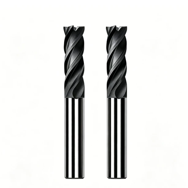
In a recent precision mold manufacturing project, we encountered a classic floor problem. After rough machining, the EDM graphite electrode dimensions looked acceptable. However, during finishing, the electrode edges chipped, positional accuracy at thin ribs failed, and the wear rate of our graphite end mills spiked. This triggered poor EDM efficiency and costly electrode rework.
These setbacks rarely stem from the graphite material alone. Instead, they involve the entire CNC graphite machining workflow, including tool selection and path planning. Over the years, we have seen many shops struggle with this exact issue. It is a common bottleneck when producing high-precision automotive molds and complex cavity electrodes.
Through extensive shop-floor experience, we learned that high-quality graphite milling requires a systematic approach. You cannot just slap any cutter onto the spindle and expect perfection. Every variable—from graphite material grades to tool geometry and cutting parameters—directly dictates your final dimensional tolerance and surface finish.
In production, we select specialized carbide end mills based on material properties and electrode complexity. Roughing standard graphite requires aggressive chip evacuation and core stability. Conversely, precision graphite electrode machining demands micro-cutting edge strength, tight runout control, and premium diamond coatings for maximum wear resistance.
We often notice that shop-floor errors come from flawed strategy rather than machine limitations. Wrong cutting speeds, excessive radial depth of cut (ae), and poor toolpaths cause severe dimensional drift. These mistakes also accelerate tool wear and ruin surface roughness (Ra).
Therefore, this guide delivers actionable insights beyond basic graphite machining theory. We outline how to stabilize your process using field-tested roughing and finishing strategies. By mastering these precision control techniques, your shop can build a highly reliable, repeatable electrode manufacturing line.
For manufacturing engineers managing tight tolerances and strict deadlines, the real question is simple. Have you established a graphite machining system capable of delivering consistent, high-quality electrodes over the long term?
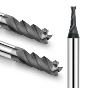
What is EDM Graphite Electrode Machining? The Core Process
Many mold shops underestimate EDM graphite electrode machining, treating it as a simple shaping task. We once consulted for a precision injection mold maker facing severe edge chipping and dimensional drift during electrode milling. Their material was premium grade, and their EDM settings were correct, yet their finished electrodes kept failing inspection because they lacked a systematic machining workflow.
True EDM graphite electrode machining integrates material physics, specialized tooling, and tailored cutting paths. The process spans from aggressive roughing to precise semi-finishing and high-speed finishing. In precision mold manufacturing, electrode accuracy dictates your final cavity replication, making process control non-negotiable for stable production.
Advantages of EDM Graphite Electrodes in Mold Manufacturing
Modern shops increasingly favor EDM graphite electrode variants over copper, especially for intricate, deep-cavity molds. Projects involving automotive components and micro-connectors require machining complex geometries like deep ribs and thin walls. Traditional materials often warp under these thin-wall conditions, whereas high-grade graphite maintains exceptional geometric stability.
Graphite offers a low coefficient of thermal expansion, high metal removal rates, and lightweight handling. By pairing the right graphite end mills with optimized CNC toolpaths, we consistently eliminate micro-chipping on fragile electrode fins. For high-end mold shops, switching to graphite is the fastest way to slash EDM cycle times while boosting cavity precision.
Differences Between Graphite Electrode Machining and Traditional Electrode Machining
A common floor mistake is machining graphite with a metalworking mindset. Some operators lower cutting speeds excessively or use standard coolant, which turns graphite dust into an abrasive paste. This ignorance destroys tool life, ruins surface finishes, and threatens the mechanical components of your CNC center.
Unlike ductile metals, graphite is a brittle material that fractures into fine chips and dust during graphite machining. It demands sharp micro-geometries, high spindle speeds, and dry cutting with high-vacuum dust extraction. We rely on specialized carbide end mills for graphite and light radial engagements to prevent severe edge blowout.
The Role of CNC Graphite Machining in the Precision Mold Industry
The real value of CNC graphite machining lies in process repeatability across high-volume electrode runs. Without standardized machining systems, tool wear and thermal drift create silent dimensional variances between identical electrodes. This inconsistency stalls the EDM floor, leading to unpredictable spark gaps and scrapped cavity blocks.
By anchoring your shop floor with a dedicated CNC graphite machining protocol, you stabilize tool wear and cutting forces. Monitoring tool deflection during the finishing stage ensures every micro-feature mirrors the CAD data perfectly. For ambitious engineers, mastering this systematic approach is what separates world-class mold manufacturing from average shop production.
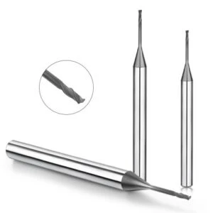
The Complete Graphite Machining System Process: From Raw Material to EDM Electrode
Many shop managers focus solely on spindle speed or buying premium cutters to fix electrode defects. However, our field experience proves that electrode quality depends entirely on a cohesive, multi-stage workflow. Every link—from raw block sourcing to structural design and CAM toolpath programming—directly dictates the final spark erosion results in the EDM pit.
Take a tight-tolerance connector mold project we recently salvaged. The client suffered from chronic dimensional drifting and chipped outer corners across multi-cavity batches. By synchronizing their graphite grade with customized tooling and balanced radial cuts, we stabilized their roughing and finishing cycles. For high-end shops, a unified CNC graphite machining system is far more valuable than modifying a single cutting parameter.
Graphite Material Selection and the Graphite Electrode Manufacturing Process
Successful production always begins with matching your graphite grade to the electrode’s geometry and EDM requirements. Graphite variants differ drastically in grain size, density, and flexural strength. Ultra-fine isotropic graphite is essential for spark-machining intricate details, whereas coarse-grain blocks excel at bulk material removal. Choosing the correct substrate is the absolute bedrock of a stable graphite electrode manufacturing process.
When milling fragile thin ribs or deep-groove profiles, material consistency prevents unexpected workpart breakage. We design custom cutting strategies based on the material’s specific density to control mechanical stress. This includes calculating precise tool diameters and leaving uniform stock allowances to protect the structural integrity of the electrode during high-feed milling.
Roughing, Semi-finishing, and Finishing in CNC Graphite Machining
High-precision electrode milling is never a single-pass operation; it requires a strict three-stage protocol. The roughing phase prioritizes rapid metal removal, high chip evacuation, and heavy machine core stability. Next, semi-finishing relieves localized material stresses, establishing a highly predictable and uniform stock allowance before the final cutter arrives.
During the final finishing stage of CNC graphite machining, the focus shifts entirely to tool sharpness, runout control, and smooth toolpath transitions. We swap out standard roughing tools for micro-grain cutters with specialized coatings to handle fragile geometric corners. For complex three-dimensional contours, dividing these phases logically is the only way to safeguard your dimensional limits.
Dimensional Control and Surface Quality Optimization in Precision Graphite Machining
The precision mold sector demands zero-tolerance accuracy and immaculate finishes for micro-structures and mirror-finish EDM cavities. Even a 5 μm error on an electrode wing can ruin a multi-cavity injection mold block. Therefore, our precision graphite machining routine prioritizes real-time tool wear monitoring, rigid work-holding, and absolute thermal stability of the CNC enclosure.
Achieving superior surface roughness (Ra) relies on smart process management over expensive hardware. We mandate regular tool-offset checks, optimize CAM corner-deceleration parameters, and run high-volume vacuum extraction to stop dust packing. Applying multiple light finishing passes rather than forcing a single deep cut keeps tool deflection near zero and ensures flawless electrode dimensions.
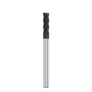
How to Select Graphite End Mills for EDM Graphite Electrode Machining?
Tool selection is the absolute make-or-break variable for maintaining dimensional stability on the shop floor. We once rescued a precision mold shop that was struggling to mill deep-cavity electrodes using standard carbide cutters. While their machines could technically cut the shapes, the tools dulled prematurely, resulting in blunt cutting edges and ruined geometric profiles. The root cause was a fundamental mismatch between generic tool geometries and the unique abrasive nature of graphite.
Selecting premium graphite end mills requires evaluating your specific graphite grain classification, electrode complexity, and spindle capabilities. The perfect cutter must balance microscopic edge sharpness, high chip evacuation, and core rigidity. In high-tolerance setups, the cutting-edge condition of micro-diameter tools dictates your final spark-gap accuracy, making targeted tool selection far more critical than simply buying generic catalog sizes.
Analysis of Graphite End Mill Edge Geometry and Machining Performance
Because graphite is a brittle material, it fractures into fine, highly abrasive micro-particles rather than continuous metal ribbons. This dust can easily pack the flutes, causing catastrophic tool breakage and severe part chipping. To combat this, we optimize flute counts and helix angles to slash cutting resistance while clearing debris instantly during intensive EDM graphite electrode machining cycles.
Our tooling strategy shifts completely between the roughing and finishing phases of production. Roughing requires thick web diameters and aggressive rake angles to absorb high structural impacts. Conversely, finishing requires pristine micro-geometries to eliminate edge blowout on fragile electrode fins. Choosing optimized tool geometries is the most effective way to eliminate dimensional drift on your finished workparts.
Material Advantages of Carbide End Mills for Graphite
Substrate toughness is your primary defense against premature tool failure and cutting vibrations on the CNC floor. For mainstream electrode applications, specialized carbide end mills for graphite provide the baseline rigidity needed to withstand abrasive wear. These heavy-duty substrates maintain tight cutting tolerances over extended, multi-stage production runs without flexing under heavy lateral loads.
We recently re-engineered a automated batch project where the client suffered from constant tool-offset adjustments due to rapid edge breakdown. By swapping their generic cutters for premium ultra-fine grain carbide substrates, we immediately stabilized their cutting forces. However, managing ultra-fine electrode details requires balancing this substrate hardness with advanced geometries and adaptive speed adjustments.
Why Diamond-Coated Graphite End Mills Extend Tool Life
For high-volume production, upgrading to diamond-coated graphite end mills is mandatory to fight the extreme abrasiveness of carbon structures. Uncoated tools suffer immediate flank wear, which alters your electrode dimensions and ruins the spark gap. High-purity diamond coatings provide a super-hard outer shield, allowing the cutting edges to stay razor-sharp even during high-speed machining.
Our field experience shows that diamond coatings offer far more than just extended tool longevity. Their primary value is maintaining predictable geometric accuracy across multiple electrode parts without frequent tool changes. When milling intricate, thin-walled electrodes, combining diamond-coated cutters with high-frequency spindles guarantees the repeatable precision that tier-one mold manufacturers demand.
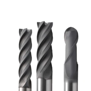
Graphite Cutting Tool Selection Guide: Key Factors Affecting Machining Efficiency
When milling intricate carbon forms, your choice of graphite cutting tools determines whether your production line runs smoothly or stalls. We once audited a precision mold shop where the machining of compact, multi-featured electrodes collapsed mid-run. As volume scaled, the operators suffered from severe tool tip recession, dimensional drift on thin ribs, and decaying surface finishes. Diagnostic testing proved that the root failure was not machine rigidity, but a catastrophic mismatch between tool geometry and graphite’s abrasive behavior.
To secure stable throughput, we evaluate cutting tools based on substrate toughness, coating tech, and cutting edge design. Different electrode shapes and graphite grades dictate entirely different tool configurations. For example, bulk pocketing requires maximum structural cross-sections for roughing stability, while micro-milling demands extreme sharpness and zero runout. Therefore, we always engineer custom tooling matrices for the specific job rather than relying on standard, one-size-fits-all tooling catalogs.
Graphite Cutting Tool Substrate, Coating, and Edge Design
Selecting a robust premium substrate is the foundational step to mastering process reliability. Even though graphite possesses low mechanical hardness, its high abrasiveness causes rapid, abrasive flank wear during continuous machining cycles. To prevent sudden edge degradation, we select sub-micron carbide substrates that offer an ideal balance of impact toughness and wear resistance.
Beyond raw substrate choice, combining the proper coating with tailored edge preparation optimizes your daily output. In automated, high-precision electrode manufacturing, a high-purity diamond coating slashes friction and blocks abrasive wear. We precisely match the hone radius and rake angles to your specific cutting depth, ensuring the tool slices cleanly without fracturing the brittle workpiece material.
Choosing Between 2 Flute and 4 Flute Graphite End Mills
We constantly optimize flute configurations based on the specific geometry of the mold electrode and the machining phase. Generally, a 2-flute graphite end mill features massive chip gash capacity, making it perfect for evacuating high volumes of dry carbon debris. This open design eliminates dust packing, making it our top choice for deep-slotting, heavy roughing, and rapid pocketing.
Conversely, a 4-flute graphite end mill features a thicker core cross-section and higher tooth frequency, providing a highly continuous cutting action. This rigid configuration minimizes deflection, making it ideal for high-speed finishing where surface roughness (Ra) requirements are ultra-strict. We never rank one over the other; we simply deploy 2-flute cutters for volumetric efficiency and 4-flute cutters for final tolerance control.
Application of Small-Diameter Graphite End Mills in Micro-Electrode Machining
As micro-molds become more intricate, shops must regularly mill tiny slots for electronic connectors and miniature terminal blocks. These micro-features require specialized, small-diameter graphite end mills that can cut deep channels without snapping. At these microscopic scales, the cutting tool must possess exceptional vibration resistance and perfect rotational accuracy to prevent wall blowing.
During micro-scale machining, our primary focus centers on controlling spindle runout, tool deflection, and individual chip loads. Because small tools have limited structural rigidity, improper feed rates or bad entry paths will instantly snap the neck or chip the electrode. We carefully dial in high-frequency spindle speeds and shallow axial depths to keep cutting forces safely below the fracture limits of the delicate carbon fins.
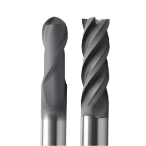
Optimizing CNC Graphite Machining Parameters: Speed, Feed, and Cutting Strategies
Most shop floor failures stem from a mismatch between cutting feeds and specific material densities, rather than bad tool selection. We once rescued a mold-making client who tried to boost their electrode output by simply cranking up the spindle speeds and feed rates. While initial material removal spiked, they quickly suffered from localized edge blowouts, terrible surface finishes, and accelerated flank wear. On-site testing proved that balancing your global cutting parameters is far more critical than chasing a single speed metric.
For stable CNC graphite machining, we engineer specific parameter matrices based on graphite particle size, cutter diameter, and part geometry. Heavy roughing stages prioritize high volume removal and structural load distribution, while finishing sequences isolate dimensional stability and fine surface quality. Rather than running static, unoptimized cookbook parameters across different setups, we continuously refine our speeds and feeds through targeted cutting loops to balance cycle time and tool longevity.
Principles for Recommended Graphite Machining Parameters
Setting reliable graphite machining parameters requires a deep understanding of carbon fracture mechanics under high loads. Because graphite shears as a brittle powder rather than a continuous metal ribbon, excessive cutting forces put massive shock loads on the cutter edge. This mechanical stress causes micro-chipping on the tool and fractures delicate electrode details. We manage this risk by adjusting spindle RPM, chip load, and step-overs in unison to distribute cutting pressure evenly.
Our cutting strategies pivot completely depending on the structural volume of the EDM electrode. Large, rigid blocks allow for aggressive chip loads, whereas thin-walled fins or micro-bosses require a drastic reduction in cutting force to guarantee geometric stability. On a busy production floor, your cutting parameters must function as a dynamic system that adapts to machine rigidity, tool wear, and part tolerances.
Optimizing Graphite Milling Speed and Feed Rate for High-Speed Spindles
High-speed machining (HSM) centers allow us to leverage extreme spindle RPMs to maximize throughput, but maxing out your controller is rarely smart. We once re-programmed an electrode project where the shop ran high RPMs alongside overly aggressive linear feeds, which instantly cooked the cutting edges. By backing off the individual chip load per tooth (fz) and re-balancing the speed-to-feed ratio, we immediately stabilized the cutting tool life.
When dialing in graphite milling speed and feed rates, we analyze the cutter’s effective flute count, neck length, and part structural rigidity. For small-diameter tools milling deep features, we strictly control feed acceleration to avoid high impact spikes during sharp directional changes. In high-speed spindle environments, maintaining a stable, harmonic-free harmonic frequency is always more profitable than pushing the physical limits of the cutter.
The Impact of Step-Over and Depth of Cut on Graphite Machining Quality
Improper engagement settings are the hidden killers of surface finish and part accuracy on the floor. This issue is highly apparent during finish passes, where your choice of radial step-over (ae) and axial depth of cut (ap) directly impacts scallop height and tool deflection. Excessive engagement overloads the tool core, while overly conservative paths cause friction rubbing, which accelerates abrasive tool wear without removing material.
Therefore, during precision graphite machining, we scale these engagement depths to match the specific profile tolerances of the electrode. For complex 3D contours that demand flawless surface finishes, we drop the radial step-over to minimize machining marks and manual bench time. For roughing cycles, we optimize the axial steps to leverage the maximum structural rigidity of the carbide core, securing a flawless balance between speed and quality.

How Does Precision Graphite Machining Achieve High Precision EDM Electrode Manufacturing?
Controlling geometric variance is the single most critical factor determining your final spark gap success. We once troubleshot a high-precision electronics mold project where the multi-cavity electrodes perfectly matched the blueprint specs, yet exhibited erratic spark gaps inside the EDM pit. Our teardown inspection traced the failure to sub-micron dimensional twisting on the corner ribs, triggered by unchecked tool deflection, harmonic spindle vibrations, and minor edge fraying during finish passes.
At our shop, successful precision graphite machining treats process stability as a unified system rather than chasing isolated parameters. Every phase—from raw pocketing to the final tool sweep—directly dictates the electrode’s physical footprint and surface micro-texture. By regulating structural stock allowances, optimizing entry paths, and constantly probing tool wear, we guarantee repeatable electrode consistency that eliminates erratic EDM discharge behavior.
Methods for Controlling Graphite Electrode Dimensional Accuracy
Securing tight graphite electrode dimensional accuracy requires a rigid, proactive floor protocol before the spindle even turns. This involves running automated laser tool-setting cycles, auditing spindle thermal expansion, and verifying the density profile of the raw block. We previously saved a deep-cavity project where a minor 5 μm uncompensated tool wear profile cascaded into severe geometric drift across an injection mold block, ruining its EDM capability.
To counter this drift, we mandate regular touch-probe calibrations, strict radial step-overs, and specialized finishing paths. For delicate thin-walled structures, reducing the chip load prevents sudden cutting force spikes from deflecting the fragile carbon walls. Our field testing confirms that running a highly predictable, balanced toolpath delivers far more reliable tolerances than blindly maxing out your linear feed rates.
Solutions for Edge Chipping and Burrs in Graphite Machining
On the shop floor, corner blowouts and edge chipping remain the biggest scrap hazards when milling brittle carbon structures. Because graphite lacks the ductility of steel or copper, thin fins and sharp intersection points break apart easily under high mechanical impacts. Dull cutting edges or poor entry angles will instantly fracture these weak geometric features, completely ruining the EDM graphite electrode before it reaches inspection.
To eliminate this structural fracturing, we optimize our tool geometries, utilize climb milling, and modify the toolpath entry angles. We deploy specialized cutters with optimized rake angles to cleanly shear the material rather than plowing it. For ultra-thin details, we leave a minimal stock allowance and apply multiple light finishing sweeps to ensure a clean edge without fracturing the base material.
Methods for Improving EDM Graphite Electrode Surface Finish
The surface quality of your EDM graphite electrode directly impacts your spark stability and the final surface finish of the steel mold cavity. For mirror-finish EDM applications, any lingering cutter marks or surface roughness on the carbon electrode will replicate onto the steel. Therefore, we manage finishing passes by isolating spindle harmonics, controlling dust buildup, and setting dedicated parameters for the final tool sweep.
For high-end finishes, we reduce the finishing step-over and swap out generic cutters for micro-grain carbide tools with ultra-smooth diamond coatings. We also run high-volume vacuum systems to pull abrasive dust away from the cutting zone instantly, preventing micro-scratching. Achieving a pristine surface finish is always a combined result of choosing the right material grade, stable tooling, and perfect parameter execution.
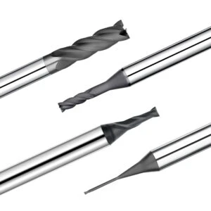
Common Issues and Solutions in Graphite End Mill Machining
Tool edge degradation is the most critical variable affecting continuous dimensional stability during long batch runs. We once consulted for a mold shop where the first few carbon electrodes passed quality control flawlessly, but subsequent parts suffered from severe dimensional drift and fuzzy surface finishes. A technical audit proved that the root cause was progressive tool flank wear altering the cutter’s effective radius, rather than machine positioning errors or bad CAM code.
In daily graphite end mill machining, edge failure never happens in a vacuum; it triggers from complex interactions between carbon grain sizes, feed speeds, and flute geometries. When analyzing a failing setup, we never simply blame the tool manufacturer. Instead, we analyze cutting mechanics, dust pack behaviors, and micro-fractures on the cutting edge to deploy an integrated, floor-ready engineering solution.
Analyzing the Causes of Rapid Graphite End Mill Wear
Accelerated wear on your cutting edges typically stems from two compounding floor issues. First is the high abrasiveness of carbon structures; though soft to the touch, raw graphite fractures into thousands of micro-grains that constantly score the tool’s flank face. Second, running unoptimized parameters—like excessive feed steps or unbalanced chip loads—creates high frictional heat that rapidly strips away protective edge coatings.
We recently re-engineered a precision multi-cavity run where the operators spiked their feed rates to cut cycle times, only to decimate their tool life. By lowering the individual chip load per tooth (fz) and matching the cutter’s core rigidity to the pocket depth, we stabilized their production output. Diagnosing tool life requires auditing your global parameter matrix, material grade, and path entry styles simultaneously.
Resolving Tool Chipping Issues in Graphite Machining
Micro-chipping along the cutting flutes is a chronic headache when using small-diameter cutters to mill deep slots or thin ribs. Because carbon is highly brittle, sudden shock loads or sharp 90-degree directional changes on the toolpath cause the edge to micro-fracture. This sudden geometric breakdown instantly changes your effective cutting offset, ruining your finished electrode dimensions.
To completely eliminate edge chipping during intricate graphite machining cycles, we optimize tool entry paths and switch to helical ramping moves. For thin-walled geometries, we slash the axial depth of cut (ap) and use light, high-frequency passes to protect the fragile cutting edges. Minimizing high mechanical impact spikes is always more effective than blindly upgrading to a harder carbide substrate grade.
Strategies for Extending Graphite Cutting Tool Life
Maximizing your graphite cutting tool life relies on structuring a highly predictable, repeatable machining workflow rather than hunting for a magic tool material. Regulating your radial engagements, maintaining high-vacuum dust extraction, and using dedicated finishing offsets are what keep cutting edges sharp over long shifts. Neglecting dust collection turns carbon powder into a highly abrasive lapping compound that eats carbide flutes.
Our long-term data proves that even high-performance diamond cutters fail prematurely if tool-offset tracking is managed poorly on the floor. We advise running structured tool-management tracking loops based on total volumetric material removal and optical edge inspections. Catching micro-wear early allows you to schedule automated tool swaps, completely eliminating scrapped electrode parts and expensive rework.
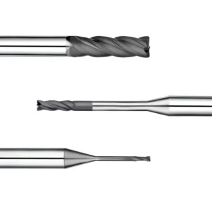
Diamond Coated Graphite End Mills vs Carbide End Mills for Graphite
Substrate and coating choices represent the dividing line between high-volume process stability and constant tool-offset adjustments. We once re-engineered a multi-cavity electrode line where standard, uncoated cutters performed beautifully during the first few setups. However, as production volumes scaled, the floor suffered from progressive dimensional drift, fuzzy surface finishes, and excessive machine downtime. Our diagnostic review proved that different machining stages require entirely different wear resistances to combat abrasive carbon powder.
We never assume one cutting tool material fits every electrode configuration. Instead, our team selects cutters based on material grain sizes, geometry complexity, total batch volumes, and target tolerances. Continuous, unmanned high-speed machining demands the extreme hardwearing nature of diamond coated graphite end mills. Conversely, for short prototype runs or aggressive rough pocketing, running flexible, optimized carbide configurations is far more cost-effective.
Analysis of Wear Resistance in Diamond Coated Graphite End Mills
Extended shopfloor tracking proves that tool failure in carbon milling comes almost entirely from continuous, abrasive flank wear. At high spindle speeds, uncoated cutting edges lose their keen micro-geometry within minutes, triggering high tool deflection and ruining your spark gaps. For high-tolerance EDM applications, running premium diamond coated graphite end mills is the only way to shield the cutting edge from abrasive recession.
The main advantage of CVD diamond coatings is their extreme surface hardness, which stays sharp across long, high-feed shifts. When milling intricate electrode details or deep thin-walled fins, these coated tools eliminate the dimensional deviations caused by frequent tool swaps. However, these premium cutters must be paired with ultra-rigid spindles and high-frequency CAM toolpaths to maximize their cost-per-part value.
Application Scenarios for Carbide End Mills for Graphite
Standard carbide end mills for graphite remain an indispensable workhorse on modern shop floors because they offer remarkable versatility. Uncoated or multi-layer nitride-coated carbide variants provide exceptional toughness and edge sharpness during volatile cutting conditions. They deliver highly stable performance and superior cost-amortization during rough pocketing, initial squaring, and rapid prototype development.
We once managed a high-pressure mold project requiring a complete set of complex electrodes turned around within a very tight deadline. Rather than burning budget on high-end coated tooling for roughing, we deployed micro-grain carbide substrates paired with high-feed CAM paths. Real-world engineering requires balancing your global tooling matrix against the total part run, rather than analyzing material grades in isolation.
Selecting the Optimal Graphite Milling Tool Based on Graphite Grade
Machining behaviors vary drastically across different carbon classifications, requiring instant adjustments to your tooling choice. For instance, ultra-fine, high-density isotropic graphite demands exceptional tool edge sharpness and tight runout control to avoid fracturing fragile corners. Conversely, roughing open cavities in coarse-grained electrode material requires a robust graphite milling tool that prioritizes core rigidity over razor-sharp geometries.
Therefore, we select our cutter profiles based on graphite grain size, shore hardness, density variations, and specific geometry requirements. For micro-electrodes with thin-walled ribs, we prioritize precise shank tolerances, tight runout, and high vibration dampening. For heavy volumetric clearing, we lock in massive core cross-sections to absorb heavy mechanical impacts, ensuring a highly predictable and profitable manufacturing process.
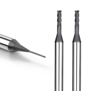
Summary of Key Factors for Establishing an Efficient Graphite Machining System
Achieving a highly predictable electrode run relies on stabilizing your global manufacturing loop rather than relying on a single premium asset. We have repeatedly proven across various automotive and connector mold projects that every variable—from grain classification to tool geometries and parameter scaling—directly dictates your final spark erosion quality. A single loose variable in this manufacturing line will trigger premature tool failure, severe corner chipping, or costly electrode scrap rates.
A world-class graphite machining system must run as a tight, closed-loop protocol combining materials, specialized tooling, adaptive parameters, and regular inspection. If you are re-engineering your current carbon shop floor, begin by cross-referencing your cutter substrates with the exact density profile of your graphite blocks. Instead of deploying isolated fixes for localized defects, adjust your global system by balancing target geometric tolerances, surface roughness (Ra), and machine cycle times.
Selecting the Right Graphite End Mills and Cutting Tools
Substrate rigidity and coating selections form the baseline foundation for any high-throughput milling environment. Tool performance requirements shift drastically based on the specific electrode geometry, carbon grain classification, and the individual machining phase. For example, volumetric stock clearing demands thick web cores and open flutes for chip clearance, while micro-milling requires razor-sharp geometries and zero spindle runout.
When milling complex electrode cavities, you must perfectly match the diameter, flute profile, and diamond coating thickness of your graphite end mills to the actual mechanical load. For continuous automated runs, never run tools based on speculative catalog lifespans. Implement on-machine tool setting and optical edge inspections to collect real cutting data, allowing you to establish a highly predictable tool replacement schedule.
Optimizing the CNC Graphite Machining Process
Most floor defects stem from a complete lack of structural process division rather than incorrect individual feed rates. A common shop error is running identical feeds and speeds across both roughing loops and final finishing sweeps, resulting in terrible cycle times and fuzzy wall profiles. Optimizing your CNC graphite machining setup requires segmenting the toolpath into distinct roughing, semi-finishing, and finishing operations tailored to the carbon form.
You must fine-tune your spindle RPMs, individual chip loads, radial engagements, and axial steps to ensure each cutter operates within its ideal mechanical window. For automated batch production, achieving high process repeatability is far more profitable than maxing out a single cycle time. Building a stable process ensures your electrodes look identical and perform predictably inside the EDM tank.
Enhancing EDM Electrode Quality through Precision Graphite Machining
In high-tolerance mold sectors, meeting blueprint specs on the coordinate measuring machine (CMM) does not guarantee clean spark erosion performance. If your carbon electrode exhibits microscopic edge fraying, localized wall deflection, or sub-micron twisting, your EDM spark gaps will fluctuate erratically. True manufacturing quality depends on managing your tool deflection, corner deceleration paths, and surface micro-texture during the final finish pass.
To elevate your output quality, anchor your shop floor with the best practices of precision graphite machining. This requires running real-time tool wear offsets, maintaining uniform stock allowances, optimizing 3D boundary paths, and running high-volume vacuum extraction. Analyzing your specific drawing geometry alongside your carbon substrate allows you to engineer a highly stable, repeatable, and high-yielding electrode manufacturing line.
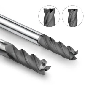
FAQ: Common Questions About EDM Graphite Electrode Milling
Controlling tool wear, process stability, and surface roughness (Ra) are the most frequent challenges discussed on our shop floor. While these milling variables seem separate, they all directly dictate your final spark gap accuracy and volumetric throughput. A small miscalculation in your CAM paths or a bad cutter choice will quickly compromise your electrode tolerances.
We compiled these practical floor questions to help you streamline your EDM graphite electrode milling operations. These answers represent field-proven insights gained from milling diverse carbon grades and complex electrode geometries. For maximum throughput, adapt these engineering guidelines to fit your specific spindle capabilities, workpiece densities, and machine rigidity.
FAQ1: What is the best graphite end mill for machining graphite electrodes?
There is no single universal tool specification that fits every carbon cavity configuration perfectly. The ideal graphite end mill must be selected based on your volumetric material removal goals and part tolerances. For large volumetric pocketing, we prioritize high core rigidity and open flutes for instant dust evacuation.
Conversely, milling thin-walled fins or micro-features requires small-diameter tools with zero spindle runout and razor-sharp geometries. When engineering your tooling matrix, evaluate the carbide substrate grade, edge preparation, and diamond coating quality. Selecting a cutter based on its physical cutting dynamics is far more effective than choosing a generic catalog listing.
FAQ2: Are carbide end mills suitable for high-speed graphite machining?
Premium uncoated or nitride-coated carbide end mills provide excellent, cost-effective stability for many carbon applications. They deliver remarkable core toughness and highly predictable cutting dynamics during standard roughing loops, squaring, and low-volume prototype runs. These cutters allow shops to maintain tight budgets while meeting quick turn-around schedules.
However, running uncoated carbide during continuous high-speed finishing cycles will cause rapid flank wear due to graphite’s high abrasiveness. High-speed carbon milling requires more than just increasing your spindle RPM. You must simultaneously optimize your individual chip load per tooth (fz), radial engagements (ae), and high-vacuum dust extraction systems.
FAQ3: Why do diamond-coated graphite end mills extend tool life?
We deploy diamond-coated graphite end mills for high-volume automated production to fight the extreme abrasiveness of carbon structures. Standard carbide substrates suffer immediate edge rounding from the thousands of micro-particles generated during cutting. This rapid wear alters your tool offsets, causing severe dimensional drift and ruined spark gaps.
High-purity crystalline diamond coatings provide an ultra-hard outer shield that maintains a keen micro-geometry over long shifts. When milling intricate electrode details or deep thin-walled ribs, these coated tools drastically reduce machine downtime caused by frequent tool swaps. This wear resistance guarantees the repeatable geometric precision that tier-one automotive mold manufacturers demand.
FAQ4: What machining parameters are required for CNC graphite machining?
Reliable parameters for CNC graphite machining must be calculated dynamically based on material density, cutter diameter, and neck extension lengths. Your global CAM configuration must regulate spindle speeds, linear feed rates, axial depths (ap), and radial step-overs (ae). Static, unoptimized parameter settings will either slow your throughput or break fragile tools.
Your speed and feed strategies must shift completely between individual manufacturing phases. Heavy roughing passes prioritize maximizing material removal rates while distributing tool load evenly across the machine frame. Finishing sweeps reduce cutting pressure, utilizing high spindle speeds and light step-overs to secure immaculate surface finishes and perfect profile tolerances.
FAQ5: How can machining accuracy be improved in precision graphite machining?
Securing tight tolerances requires looking past basic machine specifications to audit your global manufacturing loop. True component accuracy relies on minimizing tool deflection, regulating structural stock allowances, and utilizing optimized CAM toolpaths. Even minor thermal growth in your machine spindle can cause visible dimensional drift across a multi-cavity block.
To upgrade your precision graphite machining line, implement automated laser tool-setting cycles to compensate for progressive edge wear. Balance your material removal between roughing and finishing passes to ensure the final cutter encounters perfectly uniform stock resistance. For complex electrode profiles, utilize helical ramping entries and smooth corner deceleration paths to eliminate structural vibrations.






