


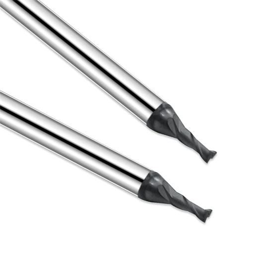
During a recent batch production run for graphite electrodes, our shop ran into a classic machining hurdle. While standard carbide tools handled the initial parts without issue, our graphite end mills began showing severe edge chipping as volume scaled up. This micro-chipping quickly led to dimensional deviations and poor surface finish. The client initially blamed poor tool life, but our shop floor records revealed a bigger picture. The failures were not caused by the tool alone, but by an imbalance across the graphite machining system.
We see this exact issue time and again when assisting clients with graphite molds, EDM electrodes, and precision components. Many machine shops try to solve tool damage by simply turning down cutting speeds. However, graphite tool chipping often stems from subtler factors. Unchecked early-stage chipping, abrasive wear accumulation, or mismatched milling feeds and speeds can all concentrate excessive force right on the cutting edge.
From our practical engineering experience, graphite itself is easy to cut, but its extreme brittleness and abrasiveness make it tricky. Dust generated during CNC graphite machining enters the cutting zone, continuously grinding away at the tool edge. If machine rigidity, dust extraction, workholding, or tool specs are slightly off, even high-end graphite end mills will suffer premature failure.
That is why a thorough graphite tool chipping analysis must look at the entire process. To pinpoint the real root cause, we evaluate five critical areas:
-
The specific type of end mill wear
-
The precise stage where edge chipping develops
-
Milling speeds and feeds tuned to the specific graphite grade
-
Tool geometry and protective coating suitability
-
Overall machining system stability and dust management
In complex mold projects, fixing the issue might mean fine-tuning machining parameters, upgrading to a diamond-coated graphite end mill, or designing a custom cutter for deep-cavity work. Every shop floor challenge requires a targeted fix rather than a generic guess.
Drawing from real-world shop cases, this article breaks down the mechanics of graphite tool chipping, failure modes, parameter optimization, and tool selection logic. Our goal is to help engineers accurately diagnose tool damage instead of relying on frequent tool swaps as a band-aid solution.
When your graphite end mills suffer from repeated chipping and unstable performance, have you identified the true culprit? Is it a defective tool, or is a hidden mismatch in your graphite machining system destroying your cutting edge?
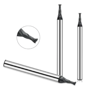
Analysis of Graphite Tool Chipping: Why Are Graphite End Mills Prone to Edge Chipping?
In our electrode machining projects, graphite tool chipping remains a common headache that degrades cutting stability. We once worked with a client producing automotive mold electrodes who faced a sudden drop in quality. After running for several hours under identical settings, their graphite end mills developed micro-chipping, causing tiny defects along the electrode edges. Our shop floor analysis showed the issue was not poor tool quality, but a dynamic imbalance between material properties, cutting strategy, and edge load.
Tool failure in graphite machining is almost always a gradual process rather than an instant break. It usually starts as microscopic edge damage that escalates into severe graphite end mill wear if uncorrected. This progression rapidly ruins part tolerance and surface finish. To prevent graphite tool chipping, we always look at the complete machining system—evaluating material density, cutter geometry, cutting parameters, and dust extraction together rather than in isolation.
How Do Graphite Material Properties Affect Graphite End Mill Chipping?
In our practical machining experience, graphite material properties directly dictate overall tool life across different material grades. While graphite has low bulk hardness, variations in grain size, density, and abrasiveness exert fluctuating impact loads on the cutter. For example, high-density fine-grain graphite delivers excellent surface finish during electrode finishing, but its dense internal structure dramatically increases the risk of premature graphite end mill chipping.
We always tailor tool selection and cutting strategies to the specific graphite material grade being machined. When shops use general-purpose tools on high-purity, high-density graphite, the cutting edge lacks sufficient impact resistance. For deep-cavity work or high-precision CNC graphite machining, we focus on strengthening core thickness, selecting robust edge geometries, and tuning parameter sets instead of blindly ramping up spindle RPM.
How Does Graphite Dust Wear Accelerate Graphite End Mill Edge Chipping?
Many machine operators underestimate how severely fine dust degrades cutting tool longevity over time. Unlike heat-driven thermal wear in metal cutting, dust wear acts like a continuous abrasive paste grinding against the tool. When fine particles flood the cutting zone without proper evacuation, micro-abrasions form along the primary flank face, rapidly triggering full-scale graphite tool chipping.
During a recent graphite mold project, a client reported that new cutters performed great initially but failed abruptly shortly after. Our on-site inspection revealed a weak dust extraction setup that allowed abrasive dust to recycle back into the cut. By optimizing dust evacuation direction and modifying toolpath strategy, we significantly reduced wear on the graphite end mill and stabilized edge integrity.
How Do the Abrasive Characteristics of Graphite Reduce Tool Life?
Based on years of shop floor testing, graphite’s relentless abrasiveness is its most challenging cutting characteristic. This continuous grinding action wears down tool flanks quickly during high-speed machining, deep-cavity milling, or long unattended production runs. Without the right carbide substrate, specialized protective coating, and geometry, early cutter failure is practically guaranteed.
Dropping feeds and speeds is rarely the right answer, as reduced throughput drives up shop operating costs. A practical approach combines optimized milling speeds and feeds with tailored cutter geometries and diamond coatings. Matching the exact tool configuration to your specific graphite grade eliminates unexpected graphite end mill failure and delivers true process stability.
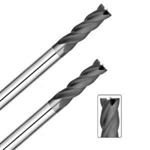
Graphite End Mill Wear Analysis: Key Mechanisms Leading to Tool Failure
In our long-term project monitoring for graphite electrodes, molds, and precision parts, we find tool failure rarely happens out of nowhere. Instead, performance degrades over time. Many operators see smooth cutting initially, but as running time accumulates, dimensional errors, rough surface finishes, and unexpected tool breakage begin to surface. On-site checks almost always trace these issues back to the steady progression of graphite end mill wear.
To maintain process control, you shouldn’t wait for a cutter to snap before taking action. Identifying early signs of wear—such as subtle edge dulling, increased cutting force, or minor edge chipping—is far more effective. Taking early corrective steps, like adjusting feeds and speeds, improving dust evacuation, or selecting a stronger geometry, prevents minor wear from turning into catastrophic graphite tool failure.
How Does Flank Wear Lead to Edge Damage?
Machinists often attribute edge chipping strictly to sudden shock loads, but microscopic inspection usually reveals heavy flank wear beneath the surface. Flank wear occurs as the cutter’s clearance face continuously rubs against the abrasive graphite workpiece. As this wear zone expands, it strips away critical structural support directly behind the cutting edge, leaving the edge vulnerable to chipping.
During a graphite mold cavity project, a client increased axial depth of cut to boost cycle times. While MRR improved briefly, accelerated flank wear rapidly weakened the cutter’s edge. Machining stability was restored only after we rebalanced cutting parameters and optimized toolpath engagement. Monitoring wear trends proactive beats waiting for a cutter to fail every time.
How Does Micro-Chipping Escalate into Tool Breakage?
When investigating graphite tool failure, we frequently see a overlooked trigger: severe tool breakage is almost always the result of unmanaged micro-chipping. Micro-chipping involves tiny edge fractures that do not instantly ruin part quality. However, as cutting cycles continue, stress concentrates at these micro-fractures, eventually triggering total structural failure of the graphite end mill.
In high-volume graphite electrode runs, a single cutter may finish several parts cleanly before suddenly chipping on the next. This abrupt failure stems from micro-chipping that went unnoticed during earlier passes. In precision CNC graphite machining, operators can spot impending failure early by checking edge condition under magnification, listening for acoustic pitch changes, and tracking surface finish drift.
How Do Tool Geometry and Cutting Edge Strength Affect Graphite End Mill Wear?
Our shop floor experience proves that cutter geometry plays a massive role in machining stability. Core thickness, flute count, helix angle, and rake/relief angles dictate how cutting forces distribute across the edge. If geometry is mismatched with your material grade, rapid graphite end mill wear occurs due to inadequate edge strength—even when using ultra-hard substrates.
We once resolved an issue involving deep-cavity graphite electrodes where standard tools yielded unpredictable tool life. By redesigning the cutter geometry to reinforce edge strength and tuning parameters to match, we achieved smooth, predictable wear behavior. When sourcing cutters, matching geometry to depth of cut, material density, and finish specifications matters far more than baseline tool price.
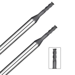
CNC Graphite Machining Stability
In our practical machining projects, graphite end mill edge chipping is rarely caused by a single isolated defect. When edge chipping occurs, operators often blame poor substrate quality or faulty coatings. However, our shop floor experience proves that cutting loads, feed rates, machine tool condition, and toolholder precision directly dictate your final machining output.
During a precision mold project, a client achieved great early results, but tool life plummeted once production volume ramped up. Our on-site analysis revealed that parameter changes put excessive stress on the cutting edge under the accelerated schedule. Before swapping tools in CNC graphite machining, evaluating dynamic cutting forces across your setup is essential.
How Do Incorrect Graphite Milling Speeds and Feeds Lead to Edge Chipping?
We frequently trace premature tool failure back to mismatched parameter settings on the CNC controller. Improper feeds and speeds destabilize cutting conditions. For instance, running spindle speeds too slow increases unit cutting force, while excessively high feed rates push chip load per tooth past the edge’s structural limit, causing instant micro-cracks.
In an electrode batch production run, a client increased feed rates to slash cycle times without adjusting RPM or axial depth. This imbalance resulted in severe graphite end mill edge chipping. We restored tool stability by rebalancing spindle speed, feed per tooth, and stepover allowance. True productivity comes from finding the sweet spot for your specific material grade.
How Does Excessive Cutting Force Exacerbate Graphite Tool Chipping?
Fluctuating cutting forces are a prime driver of premature edge failure on hard carbide tools. Excessive force usually stems from overly aggressive depth of cut, long tool overhang, or improper toolpaths. When force spikes concentrate on the cutting edge, graphite’s natural brittleness accelerates localized fracture and edge spalling.
When milling deep cavities with long tool overhang, high-speed passes create severe edge impact if cutting loads remain unadjusted. We mitigate this risk by optimizing toolpaths, reducing depth of cut per pass, and choosing rigid cutter geometries. For complex 3D contours, maintaining constant cutting load matters far more than pushing short-term removal rates.
How Do Machine Vibration and Tool Runout Affect Graphite End Mill Performance?
Over years of shop troubleshooting, we have found that many tool life issues originate from the machine spindle and clamping setup. Machine chatter and radial runout create uneven wing loading during rotation. This uneven force overburdens individual flutes, accelerating localized wear and degrading overall graphite end mill performance.
We assisted a client struggling with rough surface finishes and persistent edge chipping despite trying premium tools. Inspection revealed excessive runout caused by a worn toolholder collet, which repeatedly hammered individual flutes into the workpiece. Installing high-precision toolholders immediately restored process control. Always audit machine rigidity, spindle runout, and clamping precision alongside your cutting tools.

Optimizing Graphite Milling Speed and Feed: Methods to Reduce Graphite End Mill Chipping
When machining graphite electrodes, molds, and precision components, cutting parameters dictate process stability. When faced with short tool life, operators often rush to buy expensive premium end mills. However, our shop floor experience shows that without optimizing cutting parameters first, upgrading cutters rarely fixes the underlying issue. Setting the right graphite milling speed and feed requires balancing material density, cutter geometry, and part tolerance goals.
During a high-volume graphite mold job, a client aggressively raised spindle speed and feed rate to boost output. Instead of higher productivity, they got accelerated edge wear and poor surface finishes. Re-tuning parameters immediately restored cutting stability. In precision graphite milling, finding a balanced parameter window tailored to your setup yields far better results than chasing max speeds.
How to Select the Right Graphite Milling Speed to Extend Tool Life?
There is no universal formula for cutting speed, as material density, cutter diameter, and engagement strategy all impact edge life. Selecting the optimal graphite milling speed requires evaluating cutter strength, thermal buildup, and machine rigidity together. Running speeds too low leads to rubbing rather than clean shearing, while excessive RPM increases edge loads and accelerates abrasive wear.
When milling high-precision graphite electrodes, we tune spindle RPM to feature geometry rather than defaulting to maximum machine limits. For deep cavities, thin walls, or long tool overhangs, reducing speed prevents chatter and maintains stable cutting action. To boost productivity safely, focus on optimizing toolpaths and engagement rather than blindly driving up graphite cutting speed.
How Does the Graphite Milling Feed Rate Affect Cutting Edge Stability?
Improper feed rate selection is a leading cause of localized edge stress during graphite machining. In precision milling, feed rate directly controls the chip load per tooth. Excessive feed overloads the cutting edge and triggers micro-chipping, while an overly light feed forces flutes to rub against abrasive material, wearing down clearance angles prematurely.
In a graphite mold project, a client doubled feed rates to cut cycle time without adjusting depth of cut, causing immediate tool breakage. We stabilized the process by recalibrating feed per tooth alongside axial and radial engagement depths. A higher feed rate is not always better; keeping chip load within your end mill’s structural capacity is key.
How Does Parameter Optimization in CNC Graphite Machining Reduce Tool Wear?
Consistent tool performance stems from systematic process control rather than tweaking a single dial. CNC graphite machining parameter optimization requires harmonizing spindle RPM, feed rate, depth of cut, toolpath entry, and dust extraction. A mismatch anywhere in this loop accelerates cutter wear and destabilizes continuous production runs.
We once worked with a client experiencing wildly inconsistent tool life when machining different graphite part geometries with identical cutters. Simple flat contours and complex deep cavities require distinct cutting strategies. For complex parts, using layered step-downs, lighter step-overs, and smooth ramping paths minimizes impact forces and extends end mill life.
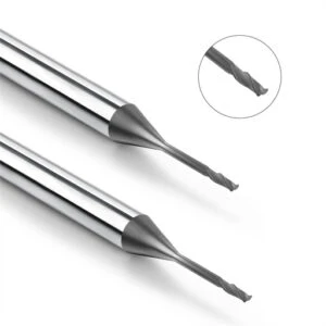
Optimizing the Graphite Machining System: Reducing Graphite Tool Chipping Through Process Improvements
In our project experience across electrodes, molds, and semiconductor components, edge chipping is rarely caused by a bad tool alone. Many clients switch cutter brands repeatedly without seeing any boost in process stability. On-site audits usually reveal misalignments between machine rigidity, workholding, dust extraction, and feed parameters. A well-tuned graphite machining system must coordinate every production variable to prevent premature graphite tool chipping.
We once serviced a client milling complex electrodes whose cutter life dropped sharply during automated production runs. Investigation showed a combination of weak dust extraction, excessive tool overhang, and unoptimized toolpaths. Once we upgraded environmental controls and streamlined path strategy, cutter performance stabilized instantly. When troubleshooting shop floor issues, analyzing the whole machining ecosystem delivers far better long-term reliability than blaming the cutter.
How Does a Graphite Machining System Enhance Machining Stability?
Achieving stable cutting requires far more than just picking a good end mill; it demands seamless synergy between machine dynamics, parameters, tool geometry, and auxiliary units. An optimized graphite machining system absorbs process fluctuations, minimizes machine vibration, and controls abrasive dust buildup. This balanced environment keeps cutting forces steady throughout long production shifts.
We always adapt system setups to specific production goals on the shop floor. For high-precision electrode work, we focus heavily on spindle runout, rigid toolholders, and smooth path planning. For long production runs, tool life management takes priority. If identical cutters yield vastly different results across different VMCs, your machine setup—not the tool—is likely the root cause.
How Does a Dust Extraction System Reduce Graphite End Mill Wear?
On the shop floor, dust control is often treated as a housekeeping issue rather than a tooling factor. Fine graphite dust is highly abrasive. If allowed to accumulate in the cut, loose particles get trapped under the flutes, grinding away the clearance land and accelerating graphite end mill wear. An efficient dust extraction setup removes particles instantly, preventing severe abrasive wear.
During a mold production audit, a client experienced erratic tool life despite using identical parameters. Inspection showed their vacuum filtration efficiency had dropped, leaving heavy dust deposits inside deep cavities. Restoring high-volume suction immediately stabilized tool wear patterns. In precision CNC graphite machining, proper dust management directly protects your cutting edge and part accuracy.
How Can Premature Tool Failure Be Avoided in Graphite Mold Machining?
Graphite mold machining involves deep cavities, tight slots, and intricate 3D contours that challenge cutter strength. Unlike general electrode milling, mold production demands hours of continuous cutting without human intervention. Unsuitable tool geometries, poor entry paths, or aggressive step-overs significantly increase the risk of sudden tool breakage.
We prevent early failures by adapting cutting strategies directly to mold architecture. In deep cavity zones, we reduce tool overhang, lower stepover engagement, and choose rigid stub-length geometries. For precision finishing, we monitor edge condition closely to maintain tight surface tolerances. Proactive toolpath optimization eliminates unexpected tool failures before they disrupt your shop schedule.
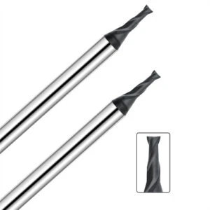
Graphite End Mill Selection: How to Choose the Right Tool for CNC Graphite Machining?
In our practical machining projects, picking the right cutter directly determines process stability and part accuracy. When faced with short tool life, operators often just switch cutter brands or buy harder tooling. However, our shop floor experience proves that true tool compatibility requires evaluating graphite density, feature depth, surface finish specs, and total cycle time together.
We once tackled a complex graphite mold project featuring deep cavities, small corner radii, and tight-tolerance electrode features. While standard cutters finished the job, they suffered rapid edge wear and dimensional drift during continuous runs. By redesigning cutter geometry, adjusting protective coating strategies, and tuning parameters, we stabilized edge performance. Always prioritize total system compatibility over a single catalog spec.
How Do Diamond Coated Graphite End Mills Enhance Wear Resistance?
During long machining runs, uncoated carbide tools suffer severe flank wear caused by continuous rubbing against abrasive graphite dust particles. Diamond coated graphite end mills utilize ultra-hard CVD diamond films to maximize surface wear resistance. This coating delivers exceptional dimensional stability when cutting dense, high-purity graphite material during long unattended production shifts.
In practical applications, we match specific diamond coatings and cutter geometries to the target workpiece geometry. For high-precision graphite electrodes requiring long cut times, we focus on coating adhesion, edge toughness, and thermal stability. A high-hardness coating cannot compensate for weak edge geometry. The coating is only one layer of defense—it must work in harmony with your complete tooling strategy.
How Do Custom Graphite End Mills Meet Complex Graphite Mold Machining Needs?
When producing precision mold components, standard off-the-shelf cutters frequently fall short in tricky features. Deep cavities, thin ribs, intricate contours, and tight corner radii require specialized tool geometries tailored to specific cutting loads. Custom graphite end mills allow us to optimize flute count, rake angles, core thickness, and reach length directly for your workpiece geometry.
During a challenging electrode milling job, a client experienced severe chatter and corner chipping when cutting deep narrow slots with standard tools. We engineered a custom stub-length cutter with a reinforced core and modified relief angles, which instantly eliminated vibration. Custom tooling is not about chasing novelty—it provides a targeted engineering fix when standard cutters fail to perform.
How to Choose a Reliable Graphite End Mill Supplier?
Based on our years of technical collaboration, choosing a tool vendor requires looking far beyond unit price or sales pitches. A reliable graphite end mill supplier must possess deep practical expertise in graphite material grades, cutter geometry design, and shop floor CNC parameters. They should analyze your actual cutting conditions rather than simply dropping off a catalog.
We often meet clients who cycled through multiple tool suppliers without fixing their underlying edge chipping issues. The root problem was rarely tool material quality, but rather the vendor’s lack of insight into machine rigidity, dust extraction, and feed strategies. When selecting a tooling partner, prioritize suppliers who provide test support, geometry customization, and ongoing engineering collaboration.
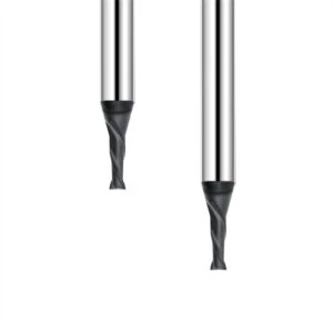
Reducing Graphite End Mill Failure Through a Comprehensive Machining System Approach
In our long-term machining experience with graphite electrodes, molds, and precision parts, cutter failure is rarely a single-variable issue. Edge chipping, accelerated wear, and dimensional drift usually stem from a mix of material density, dust accumulation, feed parameters, geometry, and machine rigidity. Reducing graphite end mill failure requires optimizing your entire production ecosystem rather than just throwing a new cutter at the problem.
Looking at real-world shop cases, process stability relies heavily on complete system integration. High-volume electrode runs demand continuous monitoring of flank wear, feed rates, and dust evacuation. Complex mold cavities require balancing cutter geometry with spindle dynamics and toolpath engagement. Because every shop setup is unique, auditing your overall machining environment is far more effective than simply cranking up cutting speeds.
Summary of Causes for Graphite Tool Chipping
Across dozens of shop troubleshooting projects, we find that graphite tool chipping is almost always a cumulative failure mode. The destructive path—from microscopic edge fractures to visible edge chipping and total cutter failure—gives clear warning signs early on. Uncollected abrasive dust, dense material structures, cutting force spikes, and runout-induced chatter all act as primary triggers.
When experiencing erratic tool life, inspect the damage pattern under magnification before blaming tool quality. On our shop floor, we analyze CNC logs, wear land progression, and surface finish changes to isolate the root cause. Determining whether the issue stems from material density, cutting parameters, or dust extraction allows for truly effective targeted fixes.
Summary of Graphite End Mill Selection and Parameter Optimization
Cutter geometry selection and parameter tuning must always be handled together. A well-engineered tool geometry provides structural edge support, while optimized milling speeds and feeds prevent force spikes on delicate flutes. Upgrading to a premium cutter or adjusting spindle RPM in isolation rarely delivers lasting stability during continuous, long-term machining runs.
When cutting dense graphite grades, deep cavity electrodes, or intricate mold features, re-evaluate cutter diameter, flute count, diamond coating, and stepover limits. Continuous production shifts demand high wear resistance, while high-precision finishing requires extreme edge stability and tight runout control. We recommend a data-driven approach built on continuous testing rather than relying on generic catalog numbers.
Partnering with a Specialized Graphite End Mill Supplier to Boost Long-Term Machining Efficiency
An ideal tooling partner does far more than drop off off-the-shelf end mills; they must understand your specific shop floor challenges. Graphite material grades, machine tool rigidity, and surface finish targets directly dictate cutter design and application strategy. A knowledgeable partner collaborates with your engineering team to refine geometries and parameter windows for maximum output.
If you are struggling with tool stability, gather your part prints, material specs, current parameters, and worn tool samples for analysis. Evaluating these real-world data points makes it easy to spot hidden bottlenecks across your workflow. For engineering teams seeking true process reliability, the goal is not finding a mythical “perfect tool,” but tuning your entire machining system for predictable performance.
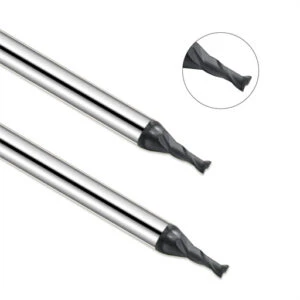
FAQ on Graphite Tool Chipping
Throughout our shop floor experience in graphite electrodes, mold making, and precision components, clients frequently ask about unexpected tool damage. Why does the service life of the exact same cutter vary drastically across different machines? Why does a job start cleanly, only for edge chipping to appear during continuous runs? These issues seem like simple tool life complaints, but they stem from a complex interaction between material density, geometry, parameters, and system rigidity.
When troubleshooting graphite tool chipping, we look far beyond the cutter itself and evaluate the entire machining environment. The following questions address common scenarios we encounter in real-world shop operations. Our answers will help you pinpoint the root causes affecting your process stability.
Why Do Graphite End Mills Chip Easily During CNC Machining?
Our analysis of shop floor cases reveals that graphite end mill chipping is rarely a sudden accident. It is almost always a cumulative process. Graphite is inherently abrasive, and fine dust generated during cutting continually pounds the primary flutes. When combined with excessive feed rates, long tool overhang, or spindle vibration, edge chipping becomes virtually inevitable.
If your CNC graphite machining yields short tool life, audit your parameter settings, holder clamping, and dust evacuation before assuming the tool is defective. In our own shop testing, we often stabilize failing processes simply by adjusting cutting loads and optimizing toolpath engagement.
How to Reduce Graphite End Mill Edge Chipping?
Minimizing graphite end mill edge chipping requires a two-part approach: selecting the right cutter and optimizing process controls. Beyond picking a geometry designed for graphite, managing chip load per tooth prevents delicate flutes from suffering sudden impact shocks.
We always advise machinists to focus on four fundamentals: ensure rigid tool clamping, minimize overhang, optimize entry toolpaths, and adjust feeds based on material density. When milling deep cavities or thin-rib electrodes, prioritizing cutter rigidity directly prevents premature edge fracturing.
What Causes a Graphite End Mill to Wear Too Quickly?
When clients report rapid wear on graphite end mills, on-site inspection usually shows that the substrate material is not at fault. Common triggers include abrasive graphite grades, improper milling speeds and feeds, weak dust extraction, or mismatched flute geometries.
Running high-density graphite at excessive RPM builds up severe friction on flutes. Poor vacuum suction allows abrasive dust to recycle back into the cut, grinding down clearance angles rapidly. Documenting tool wear under different feeds and speeds helps you identify the primary bottleneck in your process.
Which Graphite End Mill Is Suitable for Graphite Mold Machining?
Selecting tools for graphite mold machining depends on specific feature requirements rather than choosing a generic spec from a catalog. General electrode milling prioritizes material removal rates, whereas complex mold cavities and delicate ribs demand high cutter rigidity, edge strength, and fine surface finishes.
We evaluate diamond-coated graphite end mills, long-neck cutters, and custom geometries based on material grade, cavity depth, and machine precision. Analyzing part prints and cutting parameters together allows us to engineer a stable tooling solution tailored to your exact production needs.






