


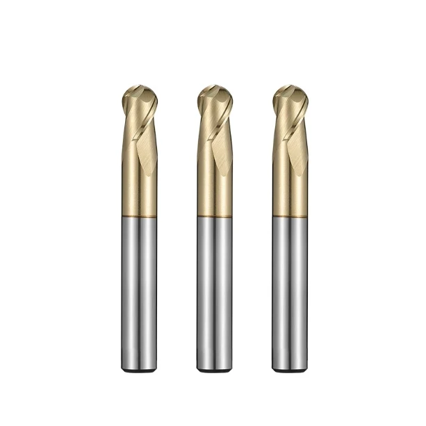
We recently received an email from a B2B client in Munich, Germany, and their frustration was palpable. Their shop was using a 5-axis setup to machine 316L stainless steel medical parts. Though planned for a four-minute cycle time, the tools kept chipping during the second operation, accompanied by severe chatter. They followed the speeds and feeds printed on the packaging, yet the tools failed after fewer than 15 parts.
For engineers like us who have spent over 15 years on the shop floor, this scenario is all too common.
When machining tough alloys, many machine shops rely strictly on standard handbook data or tooling catalog recommendations. However, stainless steel’s high work-hardening tendency, poor thermal conductivity, and sticky nature mean theoretical values quickly fail in real-world environments. Mastering parameters for end mill bits for stainless steel requires balancing machine rigidity, holder runout, coolant delivery, and dynamic milling strategies.
On our own grinding lines and across our clients’ machine shops, we have run thousands of cutting tests. Whether using 2 flute end mills for stainless steel for deep slotting or a ball nose end mill for stainless steel for 3D contouring, parameter optimization requires a tailored approach. As a specialized china end mill bits for stainless steel factory, we developed field-tested parameter guidelines based on destructive testing in our labs and direct customer feedback.
If you rely on carbide end mills for stainless steel machining, have you run into these same roadblocks? Why do premium coated carbide tools still produce harsh cutting noise and fail to reach even 80% of their expected service life?
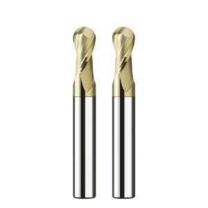
Why do the stainless steel cutting parameters determined in our workshop differ so drastically from textbook data?
When supporting shop technicians, the most common complaint we hear is: “We set our speeds and feeds exactly per the handbook, so why did our tool edges chip immediately?” The core issue is that textbook formulas assume ideal cutting conditions. In real production, stainless steel retains over 80% of cutting heat right at the cutting edge due to its low thermal conductivity. Once you factor in real-world machine deflection, toolholder clamping force, and coolant pressure, those theoretical figures quickly break down.
In our testing facility, we have pushed top-tier end mill bits for stainless steel through hundreds of limit-failure tests. Our key takeaway is simple: to balance metal removal rates with tool life, you must stop blindly relying on default catalog formulas. Under real cutting forces, austenitic stainless steel instantly deforms and work-hardens. If you cut too conservatively out of fear, the cutting edge simply rubs against the hardened layer from the previous pass, destroying the tool tip in minutes.
Avoiding Work Hardening: The Critical “Feed per Tooth” (IPT) Metric Customers Must Master
When clients experience premature tool wear in stainless steel, our first instinct is never to drop the RPM, but to inspect the feed per tooth (IPT). Upon contact, austenitic stainless steel’s surface hardness can jump from 200 HV to over 400 HV, creating a hardened layer 0.02mm to 0.05mm deep. If your feed per tooth is set too low, your actual chip thickness falls inside this hardened zone. The tool then rubs and squeezes the material instead of cutting it, causing massive heat buildup and rapid thermal degradation.
Our rule of thumb when running carbide end mills for stainless steel machining is that the cutting edge must bite completely through the work-hardened layer in a single revolution. For example, when slotting with a 10mm cutter, we advise keeping the IPT between 0.035mm and 0.06mm, even if spindle load increases slightly. Our 5-axis test data proves that once your feed rate exceeds the work-hardening threshold, cutting forces actually stabilize because chips curl cleanly, allowing the carbide’s inherent toughness to handle the load.
Comparison of safe cutting speeds (SFM) for 304 vs. 316/316L stainless steel based on practical testing
Treating 304 and 316 stainless steels identically in your CAM software is a dangerous shortcut. While both are austenitic grades, 316 and 316L contain 2% to 3% molybdenum, boosting corrosion resistance but also increasing high-temperature shear strength. This makes 316L roughly 15% to 20% harder to cut than 304. Running 316L at surface speeds meant for 304 will cause rapid, exponential flank wear and notch wear on your tool.
Through extensive shop-floor testing, we established clear surface speed (SFM) thresholds for both alloys. With proper water-soluble coolant, high-performance stainless steel end mills can run comfortably at 180–240 SFM (55–73 m/min) in 304. However, when cutting 316L, we recommend dialing back to 130–180 SFM (40–55 m/min) to prevent high-temperature adhesive wear and built-up edge. Trading a small amount of speed yields much better tool predictability, which is vital for unmanned machining setups.

Chip Evacuation and Deep Slotting: Optimizing Feed and Speed for 2-Flute Stainless Steel End Mills
In deep slotting or cavity roughing, limited chip clearance causes far more tool failures than lack of tool rigidity. Operators often choose 4-flute tools for higher feed rates, only for chips to pack tightly inside narrow slots, causing catastrophic breakage. Based on hundreds of troubleshooting cases we have resolved, the open gullet design of a 2-flute tool provides the best defense against chip packing when slotting deeper than 1x diameter (1D).
When setting up these demanding cuts, our goal is not to compromise efficiency, but to sync RPM with IPT so chips curl and evacuate smoothly. The secret to success with 2 flute end mills for stainless steel lies in controlling chip geometry: chips cannot be too thin (which causes rubbing) or too thick (which overloads the edge). Below, we outline our field-tested mathematical approach to calculating chip loads and managing feed strategy during heavy slotting.
Calculating Chip Load for 2-Flute End Mills During Full-Width Slotting
Full-width slotting (100% Ae) generates the highest cutting forces and heat levels in stainless steel machining because the tool engagement angle hits a full 180 degrees. Under this heavy radial engagement, average chip thickness is much higher than in peripheral side milling. If you use standard side-milling feed rates here, the shock load on the cutting edge will spike. As a reliable carbide end mill for stainless steel supplier, we always adjust feed calculations using engagement angle factors to protect the tool edge from micro-chipping upon entry.
For 2-flute slotting tools, we calculate feed rates backward from the maximum target chip thickness. For instance, when slotting 304 stainless with a 12mm 2-flute cutter, if your target max chip thickness is 0.04mm, your IPT should be set right at 0.04mm to account for the 180-degree wrap. If your depth of cut (Ap) exceeds 0.5D, we proactively reduce the calculated feed by 10% to 15% to maintain spindle stability and ensure clean chip ejection.
Avoiding BUE: Cooling and Feed Strategies for 2-Flute End Mills in Stainless Steel Machining
Built-Up Edge (BUE) occurs when low cutting speeds and moderate temperatures cause stainless steel to cold-weld onto the cutter’s rake face. As these welded fragments break off during machining, they tear away micro-grains of the carbide substrate, leading to severe flaking. Working closely as a china end mill bits for stainless steel factory, our internal testing shows that BUE during long slotting cycles is almost always caused by inadequate coolant delivery or hesitation in the feed rate.
To eliminate BUE, we combine high-pressure coolant with consistent dynamic feeds. Coolant pressure should ideally exceed 20 bar (290 PSI) to flush the rake face directly, cooling the cut zone and stopping material from welding to the tip. Meanwhile, your feed rate must remain steady without dwelling. Maintaining a healthy feed per tooth on 2 flute end mills for stainless steel traps cutting heat inside the chip itself, allowing the chip to carry the heat away and keeping the cutting edge clean.

Tackling Curved Surfaces and 3D Profiling: Cutting Speed Correction Rules for Stainless Steel Ball-Nose End Mills
3D profile milling remains a tough hurdle in machining stainless steel molds, medical implants, and aerospace parts. Many shop floor engineers report that even with premium coated ball-nose cutters, the center tip suffers abnormal wear or micro-chipping in under 30 minutes on shallow slopes. This happens because the cutting point shifts along the spherical radius, causing actual surface speed to drop drastically toward the tool apex.
To protect tool life on 3D contours, you cannot rely on traditional static parameter tables. When using ball-nose end mills for stainless steel, your speed logic must adjust dynamically based on actual cut depth and surface tilt. Dynamically matching spindle RPM and feed rate prevents the center tip from rubbing against metal at near-zero cutting speeds, ensuring smooth performance during corner clearance and finishing passes.
The Real Impact of Effective Diameter on RPM: Don’t Calculate Based on Nominal Diameter
Programming a ball-nose cutter using its nominal diameter (e.g., calculating RPM for 6mm on an R3 tool) causes severe under-speeding on shallow cuts. If your axial depth is light, the actual contact diameter might only be 1.5mm. This causes actual SFM to drop by over 80%, forcing the tool tip to rub against the stainless steel surface, generate intense heat, and fail prematurely.
Always calculate spindle RPM using the effective cutting diameter at your actual contact point. When running ball-nose end mills for stainless steel, using the effective contact diameter formula lets you safely boost spindle speeds. This simple geometry correction restores surface speed into the optimal cutting zone, immediately improving cutting acoustics and reducing thermal accumulation.
Extending Ball Nose End Mill Tool Life: Stepover and Feed Compensation Strategies
Setting a tiny stepover (Ae) for ultra-smooth surface finishes triggers severe radial chip thinning. The actual chip thickness becomes a fraction of your programmed feed per tooth; without feed compensation, the cutting edge merely rubs and work-hardens the surface instead of shearing metal. Maintaining tool life on an end mill ball nose for stainless steel requires adjusting your feed rate to offset this geometry.
When stepover drops below 10% of tool radius, increase your programmed IPT by 30% to 50% so the edge actively bites into the workpiece. Additionally, tilting the spindle on a 5-axis machine keeps the zero-speed center tip off the workpiece. This technique exponentially extends tool life while eliminating hours of tedious manual polishing.
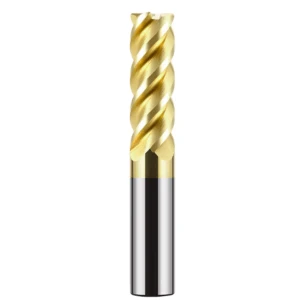
HEM in Practice: Secrets to Boosting Parameters with Carbide End Mills for Stainless Steel
The old rule of “low RPM, slow feed, and shallow cuts” for stainless steel is inefficient and outdated. Modern High-Efficiency Milling (HEM) utilizes light radial engagement (low Ae) paired with full axial depth (high Ap). This dynamic strategy transfers cutting heat directly into the chip rather than the part, driving a massive leap in both Metal Removal Rate (MRR) and tool life.
Executing dynamic HEM paths requires rigid tool geometry and heat-resistant carbide grades. When deploying high-performance carbide end mills for stainless steel, parameter setups cannot mirror traditional side-milling numbers. By applying radial chip-thinning formulas, you can push table feeds to limits once thought impossible while keeping spindle load smooth and cycle times extremely short.
Leveraging the Chip Thinning Effect: Boosting Feed Rates by 200% with Low Radial Engagement (Ae)
Running a 5% to 10% radial width of cut (Ae) at standard catalog IPT produces powdery, ultra-thin chips. This causes the cutting edge to rub repeatedly upon exiting the cut, spiking heat and rapidly inducing work hardening. In tough stainless steel, this constant micro-friction degrades the tool’s flank face within minutes.
To fix this, apply a Radial Chip Thinning Factor (RCTF) to recalculate feed rates. When running a 5% Ae cut with dedicated carbide end mills for stainless steel machining, we recommend increasing programmed feed rates by 150% to 200%. This restores actual chip thickness to a healthy cutting load, preventing edge rubbing while reducing thermal exposure time on each tooth.
Retraction and Feed Rate Adjustment for 4-Flute and 5-Flute Carbide End Mills in Side-Milling Finishing
When switching from roughing to side-wall finishing or corner cleanup, the focus shifts to wall perpendicularity and surface finish. Stainless steel tends to push back (springback) against the tool, leaving chatter marks if flute counts or retraction paths are wrong. Our field tests highlight distinct rigidity and force distribution differences between 4-flute and 5-flute designs during side passes.
For high-precision side walls, we recommend using 5-flute carbide end mills for stainless steel machining. The 5-flute core provides higher static rigidity to suppress tool deflection, while extra cutting edges allow high table feeds at micron-level chip loads. Always use arc-in/arc-out (ramp in/out) entry moves to prevent dwell marks, delivering a mirror-like wall finish in a single pass.
The Critical Impact of Tool Runout and Clamping Systems on Actual Feed Rates for Stainless Steel End Mills
After diagnosing thousands of field issues, we find that tool holder runout is a severely underestimated cutter killer. When tools break or wall finishes look rough, operators often blame cutter quality or lower cutting speeds. In reality, even premium stainless steel end mills fail rapidly if clamping runout throws off cutting load balance among the flutes.
Runout causes uneven tooth loading: a tool with 0.01mm runout forces one flute to take double its intended workload while the opposite flute barely cuts. On tough stainless steel, this single-flute overload triggers instant micro-chipping, causing a domino effect that destroys the entire end mill within seconds. System precision is non-negotiable for consistent tool performance.
Adjusting Feed Per Tooth to Prevent Tool Breakage When Runout Exceeds 0.005mm
We always advise customers to keep total assembly runout under 0.003mm. However, worn spindle tapers, dirty collets, or improper torque often push runout past 0.005mm in production environments. When clients experience frequent tool breakage on 316L, our first troubleshooting step is re-evaluating the peak load on the most heavily engaged flute.
If you cannot replace worn tool holders immediately, apply a feed rate compensation method. When running a 4-flute end mill bits for stainless steel with 0.008mm runout, drop programmed IPT by 20% to 30%. This adjustment brings peak tooth loads back into a safe operating zone, preventing sudden tool breakage until proper holders are installed.
Measured Differences in Limit Parameters for Stainless Steel End Mills: Shrink-Fit vs. Hydraulic Holders
In our test lab, we ran identical carbide end mills for stainless steel machining in collet chucks, hydraulic holders, and shrink-fit holders. The results were striking: holder rigidity and vibration dampening directly dictate how hard you can push operational parameters.
Shrink-fit holders excel in HEM dynamic milling thanks to minimal overhang and sub-0.003mm repeatable runout, allowing max axial depths and 25% higher SFM without chatter. Meanwhile, hydraulic holders excel at deep-cavity finishing because internal fluid chambers absorb micro-vibrations, yielding wall finishes that approach mirror quality. Matching holder mechanics to your process unlocks your cutter’s full potential.
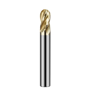
Parameter Limits from the Production Perspective: Empirical Validation by a Chinese Manufacturer of Stainless Steel End Mills
End-users often wonder how cutting charts are derived, assuming they stem from simple theory. However, as a dedicated factory specializing in end mill bits for stainless steel, we know every shop-floor parameter comes from grueling cutting trials. The challenges of machining stainless steel—such as high heat, built-up edge (BUE), and work hardening—force us to validate physical tool limits during manufacturing.
Data gathered in our grinding and testing workshops explains why theoretical numbers fail in real-world jobs. Parameter limits are not arbitrary; they depend on carbide substrate phase structures, edge preparation quality, and coating heat thresholds. Understanding these physical boundaries helps engineers fine-tune speeds and feeds safely, avoiding catastrophic edge failure while maximizing machining efficiency.
The Manufacturer’s Perspective: How Substrate Grain Size and Coatings Determine Heat Limits for Stainless Steel End Mills
Macro-geometry matters, but micro-structure determines a tool’s true operational limit. We engineer tools using ultra-fine (0.4μm to 0.6μm) carbide substrates, balancing extreme edge hardness with high Transverse Rupture Strength (TRS). When cutting stainless steel generates intense thermal stress, this fine-grained substrate stops micro-cracks from spreading, allowing higher recommended feed rates (IPT).
Coatings form the second line of defense for cutting speed (SFM) limits. Traditional TiAlN coatings degrade above 800°C—a threshold easily crossed when slotting 316L. On our high-end carbide end mills for stainless steel machining, we apply high-aluminum AlCrN nano-coatings rated up to 1100°C. This layer reduces friction, prevents cold-welding, and boosts steady-state cutting speeds by over 30%.
Conducting Destructive Testing at Our Stainless Steel End Mill Factory
To provide reliable parameters for overseas B2B clients, our quality lab features 5-axis machining centers and dynamic force sensors. As a specialized china end mill bits for stainless steel factory, we subject every batch to destructive testing. Rather than gathering data under light loads, we drive cutters directly into 304 blocks for full-width slotting, increasing RPM and axial depth in 5% steps until failure.
This rigorous testing precisely maps the tool’s physical limits under mechanical overload and thermal failure. Using electron microscopes, we analyze initial micro-flaking patterns along the cutting edge. These first-hand destructive test results—derived directly from our manufacturing facility—form the technical foundation for resolving complex field challenges.

Procurement and On-Site Optimization: How to Obtain a Tailored Parameter Sheet from Your Carbide End Mill Supplier for Stainless Steel
There is no “one-size-fits-all” parameter formula for stainless steel machining. Our technical support experience proves that identical cutters perform differently on a 15 kW machining center compared to a 7.5 kW light-duty mill. Instead of relying on generic packaging labels, treat your supplier as an engineering partner to translate actual shop conditions into optimized tool performance.
The fastest route to efficiency is requesting a customized cutting database from your carbide end mill for stainless steel supplier. If you face high tool wear or are setting up tough 304/316 jobs, compile a list of your machine power curves, holder types, and coolant pressure. Sharing this data helps eliminate over 80% of early chipping issues caused by low machine rigidity or mismatched spindle torque.
Providing Machine Rigidity and Spindle Power Data to Your Carbide End Mill Supplier for Customized Cutting Parameters
Machine torque curves are frequently overlooked during parameter setup. A spindle might deliver constant torque at 3,000 RPM but drop power significantly at 8,000 RPM. If you run a large-diameter cutter in a low-torque zone, minor RPM fluctuations cause severe chatter, instantly tearing the cutting edge of end mill bits for stainless steel.
When evaluating new stainless steel jobs, provide your supplier with your machine interface (BT/HSK), spindle power/torque charts, and machine age. With these metrics, technical teams can calculate exact spindle load percentages across varying cut depths. This allows them to build a tailored speed and feed chart that balances machine capacity with maximum tool life.
On-Site Troubleshooting Checklist: Quickly Adjusting S/F Parameters Based on Chip Color and Noise
You do not need a microscope to check tool wear during production; chip appearance and cutting acoustics serve as your best dashboard. When milling stainless steel with end mill bits for stainless steel, ideal chips should appear silver-white or pale yellow, tightly curled into C-shapes. Dark blue chips mean cutting temperatures have passed 600°C; immediately reduce cutting speed (SFM) or adjust coolant flow.
High-pitched squealing or jagged chip edges indicate system vibration; check holder runout first, then increase feed per tooth (IPT) by 10% to 15% to help the edge bite deeper. A low growling sound paired with spiking spindle load means flutes are packing with chips. Immediately reduce axial depth of cut or switch to a 2-flute design for better chip clearance.






