


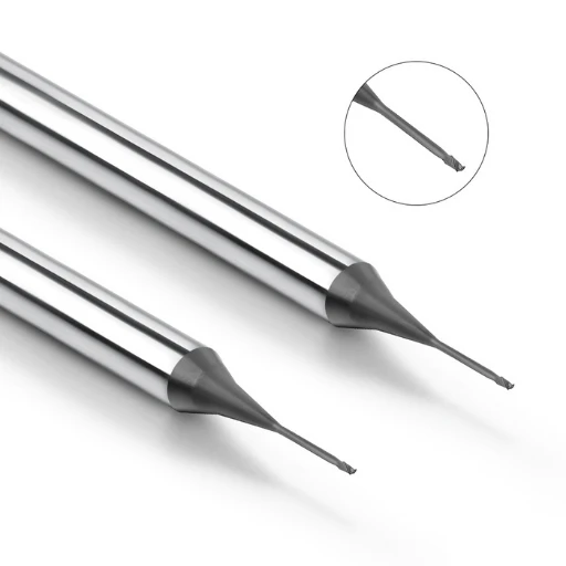
In precision graphite machining, a frustrating challenge frequently arises. Even after optimizing machine accuracy, CAM programming, and shop floor workflows, operators still face sudden graphite end mill failure during production runs.
We recently assisted a client specializing in complex graphite electrode machining. While initial sample parts passed dimensional inspection, batch production suffered from frequent tool damage. Deep-cavity operations using long-reach tools resulted in severe micro-chipping and total shank breakage, increasing downtime and tooling costs.
On-site root cause analysis revealed that graphite tool failure rarely stems from a single factor. Instead, it usually results from a combination of cutting force fluctuations, thermal shock, improper tool geometry, and abrasive dust buildup.
By transitioning to specialized necked graphite end mills, refining chip evacuation, and optimizing engagement parameters, we successfully eliminated catastrophic tool failure. Achieving process stability requires selecting cutting tools specifically engineered for the unique abrasive nature of graphite.
Engineers often ask why identical tools produce vastly different tool life results under the same programmed feed rates. Solving this unpredictable tool breakage requires a structured diagnosis across three key levels: tool design, cutting parameters, and machine system rigidity.
Analysis of Graphite End Mill Breakage: Why is Tool Damage Common in CNC Graphite Machining?
In precision graphite electrode production, unexpected graphite end mill breakage remains a critical challenge for continuous manufacturing stability. Many shop managers initially blame tool material hardness, but on-site diagnostics show that graphite material behavior, tool geometry, cutting forces, and chip evacuation collectively dictate tool performance.
During a recent cavity machining project for mold electrodes, standard carbide tools performed acceptably in roughing but suffered sudden edge chipping during finishing passes. By optimizing tool geometry, adjusting cutting parameters, and improving dust management, we restored machining stability. Preventing tool failure requires evaluating the entire CNC graphite machining system rather than isolating a single variable.
How Do Graphite Material Properties Affect Tool Breakage?
Although graphite exhibits low overall hardness, its brittle structure and micro-granular makeup severely strain cutting edges. During cutting, abrasive particles fracture off and inflict micro-impacts on the tool tip. If tool sharpness and edge strength are mismatched with material density, graphite end mill breakage quickly follows.
When machining dense, fine-grained graphite for EDM electrodes, edge stability becomes paramount. Heavy cut depths or aggressive feed rates can trigger sudden cutting force spikes in high-density graphite, accelerating the shift from predictable fluting wear to catastrophic shank failure.
How Does Graphite Dust Accelerate Edge Chipping?
Abrasive micro-dust management is frequently overlooked on the shop floor. Without immediate extraction, fine graphite dust packs into the cutting zone, building up on tool flutes and workholding fixtures. This trapped powder dramatically increases friction, generating thermal shock and localized fatigue along the cutting boundary.
We diagnosed a micro-machining line where small-diameter tools experienced mysterious tip chipping after several hours of operation. Inspection revealed that localized dust packing degraded air-cooling efficiency and jammed flute clearance. Integrating targeted high-vacuum dust extraction with optimized flute designs completely eliminated the premature chipping.
How Do Improper Machining Conditions Lead to Graphite End Mill Failure?
In many cases, graphite end mill failure stems from mismatched cutting dynamics rather than sub-par tool quality. Deep-cavity operations with extended tool overhang often induce severe tool chatter if spindle speed, feed per tooth, and radial engagement are improperly balanced. This vibration subjects brittle tool edges to destructive cyclic loads.
Rigidity and clamping stability are non-negotiable when working with long-reach or micro-diameter end mills. When tool breakage spikes, we advise analyzing dynamic cutting forces and runout before upgrading to premium carbide grades—system instability is usually the real culprit.
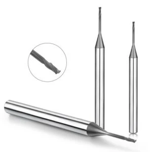
Analysis of Graphite Milling Cutting Forces: How Do Cutting Forces Cause Graphite Milling Cutter Breakage?
During precision graphite electrode machining, instantaneous cutting force spikes are a primary cause of unexpected tool failure. While operators typically focus on spindle speed and feed rate, brittle materials like graphite are highly sensitive to sudden load changes. In deep-slotting or high-material-removal passes, unmonitored cutting forces quickly exceed the mechanical threshold of the tool’s cutting edge.
We diagnosed a mold electrode project where tools repeatedly failed during the transition from roughing to deep-cavity finishing. Analysis confirmed the failure was not due to poor wear resistance, but rather dynamic load spikes during toolpath directional changes. By refining engagement angles and stock allowances, we stabilized the graphite milling cutting forces, completely resolving cutter breakage.
How Do Excessive Graphite Milling Cutting Forces Cause Tool Chipping or Breakage?
In field investigations, graphite tools rarely fail from slow, uniform flank wear; instead, they suffer sudden edge chipping or catastrophic fracture. This failure mode points directly to severe cutting load spikes. Aggressive feed rates, excessive axial depth of cut, or harsh tool entries inflict high impact loads that initiate micro-cracks along brittle carbide edges.
When machining thin-walled graphite electrodes with micro-diameter end mills, cutting force control is paramount. Reducing the depth of cut per pass and using smooth adaptive toolpaths provides far better results than raw cutting speed. Preserving edge integrity throughout the entire machining cycle is essential to preventing graphite milling cutter breakage.
How Does Uneven Tool Loading Reduce Graphite End Mill Life?
Machinists often ask why tools from the same batch exhibit vastly different wear rates under identical settings. Unbalanced tool loading is almost always the culprit. High runout, dynamic tool holder deflection, or toolpath strategies that concentrate load on a single flute accelerate localized chipping and dramatically reduce total graphite end mill life.
Maximizing tool longevity requires verifying spindle runout, holder clamping force, and flute design compatibility before cutting. While multi-flute designs increase chip clearance challenges, tailored geometries balance radial forces far more effectively. Tailoring tool geometry to specific graphite grades yields far better process stability than pushing unsafe parameters.
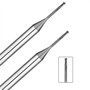
Why Are Long-Neck Graphite End Mills More Prone to Breakage During Deep-Cavity Machining?
Machining deep-cavity graphite electrodes requires extended overhangs, which inherently reduce tool rigidity. Long-neck graphite end mills lose flexural strength as their reach increases, making them highly susceptible to micro-vibrations under lateral cutting forces. Failing to adjust radial load for high length-to-diameter ratios quickly triggers severe chatter and shank failure.
In a deep-cavity electrode project, a client experienced constant tip chipping when trying to cut deep pockets in a single pass. We solved this by shortening the tool extension to the absolute minimum, reducing radial engagement, and introducing trochoidal entry paths. Successfully operating long-neck tools requires a holistic balance of tool stiffness, force direction, and damping stability.
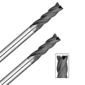
The Impact of Graphite End Mill Geometry: How Tool Structure Determines Fracture Resistance
In high-precision graphite machining, tool failure is rarely just a matter of material hardness or feed rates—it is heavily driven by structural design. Key architectural elements such as core thickness, flute volume, and cutting edge preparation dictate how effectively an end mill distributes dynamic cutting stresses. Optimizing overall graphite end mill geometry ensures balanced load distribution, directly preventing premature wear and sudden tool breakage.
During a complex mold electrode project, tools made from identical carbide grades exhibited drastically different service lives due to geometric variations. While one design cut smoothly at first, it suffered severe edge failure as cavity depth increased because its core rigidity was mismatched with the cutting forces. Consequently, we evaluate flute design, material density, and part geometry holistically rather than relying solely on flute count or standard tool dimensions.
How Does Flute Count Affect Graphite End Mill Breakage?
Selecting the correct flute count directly governs cutting force equilibrium and chip evacuation efficiency. Because graphite produces fine abrasive dust rather than continuous metal curls, insufficient flute clearance causes rapid dust packing. This packed powder generates intense frictional heat and localized pressure, significantly increasing the risk of premature graphite end mill breakage.
Roughing passes require generous flute gullets to clear heavy dust volumes, whereas finishing operations demand higher edge density to maximize surface finish and tool rigidity. When machining intricate graphite electrodes, using a tool with too many flutes restricts dust flow, while too few flutes compromises core strength. Matching flute count to specific machining goals is essential for process stability.
How Do Helix Angle and Core Thickness Designs Optimize Graphite Machining Stability?
Evaluating helix angles and web thickness is vital when diagnosing persistent graphite tool failure. An optimized helix angle softens initial tool entry and redirects cutting forces vertically up the spindle, while a thick core boosts flexural rigidity to minimize dynamic deflection. Together, these geometric features prevent harmonic vibration from micro-fracturing brittle carbide flutes.
We resolved a deep-pocketing issue where slender tools left chatter marks and suffered frequent tip chipping. By transitioning to a web-tapered end mill with reinforced core thickness, we stabilized the tool column and eliminated vibration. When operating with long tool overhangs, prioritizing structural stiffness over aggressive cutting speeds consistently yields superior reliability.
How Does Graphite End Mill Geometry Reduce the Risk of Edge Chipping?
Edge chipping poses a constant threat when milling thin walls, sharp corners, and high-precision graphite electrodes. To prevent micro-fractures, the tool edge must maintain an optimal balance between razor sharpness and structural strength. Tailoring graphite end mill geometry ensures efficient force dissipation along the cutting edge, drastically reducing the risk of edge chipping during continuous production.
Preventing edge chipping requires more than just increasing carbide hardness; it demands precise edge hone preparation, positive rake angles, and robust web support. On finishing passes, an overly sharp edge without adequate structural backing may yield fine surface finishes initially, but it quickly micro-chips under continuous friction. Customizing edge geometry to the application achieves the ideal balance between dimensional precision and extended tool life.
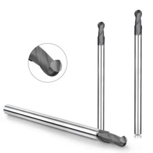
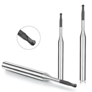
Causes of Breakage in Small Diameter Graphite End Mills: Key Issues in Micro-Tool Machining
In high-precision electrode shop floor operations, tool breakage in small-diameter graphite end mills remains a primary source of unexpected downtime. When milling intricate ribs, narrow slots, and micro-cavities, smaller cutter diameters satisfy fine detail demands but suffer from drastically reduced flexural rigidity. Operating micro-tools requires strict environmental controls and refined CAM strategies to maintain cutter stability.
We recently assisted a client machining micro-mold electrodes featuring deep, narrow slots and sharp internal corners. Their standard micro-end mills routinely snapped after cutting just a few parts due to excessive overhang, dynamic chatter, and unpredictable force spikes. By shortening tool projection, smoothing toolpath entries, and lowering radial engagement, we achieved consistent tool life and reliable batch production.
Why Are Small Diameter Graphite End Mills More Prone to Breakage?
As tool diameter decreases, cross-sectional area drops exponentially, severely compromising the tool’s resistance to bending moments. When encountering localized hard spots in graphite, aggressive feed rates, or sudden vector changes, small-diameter graphite end mills undergo elastic deflection. This bending concentrates intense mechanical stress at the cutting edge, causing immediate shank snapping or tip failure.
Micro-tool machining for precision graphite electrodes frequently demands long reach ratios to clear deep features. Selecting an end mill with excessive flute length induces harmonic vibration and rapid fatigue, even under conservative feed rates. Preventing premature tool failure requires selecting the absolute shortest flute length and largest core diameter permissible by part geometry.
How Can Vibration and Cutting Loads Be Controlled When Using Micro-Diameter Graphite Tools?
Achieving success in micro-tool machining depends on maintaining a uniform cutting load rather than pushing high spindle speeds. Small-diameter tools amplify minute system vibrations, subjecting fragile tool tips to relentless micro-impacts. Unchecked spindle runout, tool holder imbalance, or improper collet clamping will instantly ruin cutting edges and dramatically shorten tool life.
To mitigate vibration, we minimize tool overhang, optimize chip load per tooth, and reduce axial depth of cut. Utilizing high-RPM spindles with near-zero runout and adopting adaptive trochoidal clearing paths stabilizes dynamic loads far more effectively than cutting speed adjustments. When micro-tools fail, diagnosing vibration sources should always precede replacing tool brands.
How Do You Select the Right Small Diameter End Mill for Precision Graphite Machining?
Selecting the optimal small-diameter end mill for precision graphite machining requires evaluating material grain size, wall thickness, and feature depth. Milling delicate electrode details demands high edge sharpness and tight dimensional tolerances, whereas deep-slotting requires maximum core thickness and generous dust clearance flutes. Identical tool diameters require completely different geometries depending on the feature being cut.
A successful micro-machining process relies on pairing the proper length-to-diameter ratio with machine tool precision and rigid workholding. For high-precision graphite parts, matching tool neck length to feature depth and tailoring cutting parameters to material density guarantees dimensional accuracy while maximizing tool longevity.
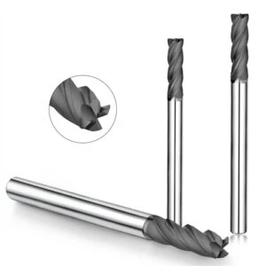
Optimizing Graphite Machining Systems: How to Reduce Tool Breakage?
In semiconductor component and precision electrode manufacturing, abnormal tool damage rarely stems from the tool alone. We frequently observe shop floor scenarios where identical tool batches operating on the same graphite material produce drastically different tool life across different CNC machines. While one machining center runs continuously without issue, another suffers from persistent edge chipping and premature shank failure.
Field experience proves that achieving stable graphite machining requires evaluating the entire ecosystem—machine rigidity, spindle health, cutting parameters, and abrasive dust extraction. A reliable system fosters dynamic synergy between the cutter, machine tool, and operating environment rather than relying solely on upgrading tool grades. When addressing constant tool failure, reviewing process compatibility across the shop floor is always more effective than swapping cutters.
How Do CNC Machine Rigidity and Spindle Stability Affect Tool Life?
Machine condition is an often-overlooked factor during root cause analysis of graphite end mill failure. Although graphite exhibits relatively low cutting resistance, its brittle structure makes carbide edges highly sensitive to dynamic vibration. If machine guideways lack stiffness, spindle runout exceeds tolerances, or toolholders lack clamping force, micro-vibrations develop during cutting and cause rapid micro-chipping.
During an electrode production run, a client experienced inconsistent tool life across identical VMCs using identical programs. Dynamic diagnostics revealed that one machine’s spindle suffered from severe runout under load. After re-aligning machine geometry, re-balancing the spindle, and upgrading to precision shrink-fit holders, tool failure dropped significantly. Ensuring spindle stability and machine accuracy is the essential foundation for long tool life.
How Can Machining Parameters Be Optimized in a Graphite Machining System?
Optimizing parameters requires far more than simply reducing spindle speed or feed rate when tools break. Effective optimization requires balancing cutting dynamics around material grain size, end mill geometry, and part feature depth. Lowering feed rates without adjusting axial depth of cut or toolpath entry often fails to solve breakage problems.
Through field trials, we harmonize spindle RPM, feed per tooth, and engagement depth based on tool overhang and feature geometry. In deep-cavity or thin-rib passes, reducing chip load per tooth prevents sudden mechanical shock along fragile flutes. Proper parameter tuning allows shop managers to minimize tool breakage while preserving high material removal rates and tight tolerances.
How Does Dust Management Reduce Abnormal Tool Wear in Graphite Machining?
Continuous project monitoring confirms that abrasive dust evacuation directly dictates edge stability. CNC graphite machining generates massive volumes of fine dust that, if left in the cut, packs into flute gullets and recutting zones. In high-speed milling, trapped graphite dust increases friction, spikes temperatures, and accelerates abnormal tool wear in graphite machining.
We resolved a continuous milling project where tools cut clean initially but degraded rapidly after a few hours of operation. Diagnostics showed an underpowered vacuum extraction setup, causing fine abrasive dust to recirculate and abrade the flutes. By boosting vacuum extraction volume, selecting tools with optimized flute spacing, and using air-blow toolpaths, we restored stable chip clearance and eliminated premature wear.
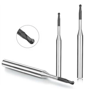
Choosing a Graphite End Mill Manufacturer: How Tool Design Prevents Tool Breakage
In precision graphite electrode and component machining, severe tool damage often stems from inadequate cutter engineering rather than operator error. Because graphite is extremely brittle and abrasive, core parameters like edge strength, flute volume, substrate density, and coating integrity directly dictate performance. Choosing an experienced tooling partner prevents costly trial-and-error on the shop floor.
We once consulted for a shop experiencing severe edge chipping on complex graphite electrodes despite optimized machine parameters and toolpaths. Engineering analysis revealed that their off-the-shelf tooling lacked the edge prep and flute volume required for abrasive dust clearing. A reliable graphite end mill manufacturer must deliver application-specific designs tailored to exact graphite grades and part geometries rather than generic cutters.
How Do Professional Graphite End Mill Manufacturers Optimize Tool Structure?
Engineering high-performance graphite cutters requires precise balancing of edge hones, core thickness, helix angles, and rake geometry. Over-emphasizing edge sharpness reduces mechanical load capacity, causing immediate chipping. Conversely, over-reinforcing the cutting edge increases cutting resistance, inducing tool deflection and subpar surface finishes.
When optimizing tools for a client’s deep-cavity electrode project, we re-engineered the flute-to-diameter ratio, expanded dust evacuation channels, and reinforced core rigidity. This structural redesign eliminated chatter and enabled sustained, vibration-free milling over extended unattended shifts. Superior graphite tool engineering integrates substrate properties, feature depths, and machine dynamics into a single cohesive design.
How Do Diamond Coated Graphite End Mills Enhance Wear Resistance?
Standard carbide tools quickly suffer abrasive wear and dimensional drift when continuous-milling high-purity or fine-grained graphite. Abrasive micro-dust constantly erodes bare carbide flutes during long production runs. For high-volume manufacturing, diamond coated graphite end mills provide the hardness necessary to maintain tight tolerances and edge sharpness over extended cycles.
In high-precision electrode applications, diamond coatings dramatically boost surface hardness and lower friction coefficients along the flute. However, coatings are not a cure-all; the underlying carbide substrate and macro-geometry must match the application. Without a rigid substrate and correct edge hone, even advanced CVD diamond coatings will suffer premature flaking and edge failure.
How Do You Select the Right Graphite End Mill for a Specific Application?
Achieving optimal tool life starts with evaluating graphite grain size, feature geometry, pocket depth, and surface finish targets rather than picking stock tools. Precision electrode milling demands razor-sharp edge retention, whereas heavy roughing requires high core strength and high material removal rates. Application demands dictate the exact cutter specification.
Successful graphite end mill selection requires matching tool diameter, neck overhang, flute geometry, and coating technology with machine spindle capabilities. Deep pockets call for high-rigidity long-neck cutters, while intricate features demand stabilized micro-tools. The key is not finding a generic “hardest” tool, but selecting the specific cutter designed to handle your exact machining dynamics.
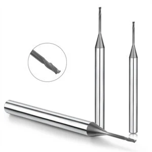
Preventing Graphite End Mill Failure: Methods to Reduce the Risk of Tool Breakage
In shop floor operations, sudden cutter breakage is rarely caused by a single isolated defect. Instead, it results from interconnected failures across tooling, machine precision, parameter selection, and CAM programming. When tools fail, operators often instinctively switch to premium carbide grades; however, without addressing root-cause machining conditions, new cutters will fail just as quickly.
We consulted for an electrode manufacturer facing erratic cutter longevity, where identical tools completed multiple parts one day but suffered edge chipping mid-pass the next. Audit logs showed the instability stemmed from mismatched feed rates, excessive tool overhang, and spindle runout. Resolving tool failure requires optimizing the entire manufacturing workflow rather than applying temporary fixes to individual symptoms.
Optimizing Graphite Machining Parameters to Extend Tool Life
Establishing proper cutting parameters is essential for maintaining edge stability in brittle materials. Although graphite generates lower cutting resistance than alloy steels, its abrasive nature means unmonitored feed rates, heavy depths of cut, or force spikes will fracture brittle carbide edges. Parameters must be adjusted based on material density, feature geometry, and cutter dimensions.
When milling high-precision graphite electrodes, lowering axial depth of cut per pass maintains a stable cutting state, while roughing operations require balancing material removal rates with tool load capacities. Pushing feed rates blindly often increases downtime due to frequent tool changes, disrupting shop production rhythms. Precisely balancing spindle speed, feed per tooth, radial engagement, and axial depth is key to preventing graphite end mill failure.
Selecting the Right Graphite End Mill Geometry Based on the Machining Scenario
Matching cutter architecture to specific part features dictates long-term machining reliability. Cutters with identical diameters and substrate grades exhibit vastly different tool lives depending on their core designs. Deep-pocketing requires maximum core stiffness and vibration resistance, whereas finishing thin-walled ribs demands razor-sharp edge stability and tight dimensional control.
We re-engineered the tooling strategy for a shop machining complex-surface mold electrodes to fix inconsistent tool life and rough surface finishes. By optimizing core taper, flute gullet ratios, and dust evacuation channels, the new tools distributed cutting loads evenly. There is no universal “best” tool design; preventing tool failure depends on choosing specific geometries for deep slots, micro-features, or thin walls.
Boosting Graphite Machining Efficiency Through Synergy of Tools, Equipment, and Parameters
Isolated optimizations deliver limited performance gains on the shop floor. Achieving long-term production stability requires complete synergy between cutter capabilities, machine tool rigidity, workholding accuracy, and CAM parameters. Even high-grade diamond coated end mills will suffer premature wear or shank breakage if loaded onto a worn spindle or driven by aggressive toolpaths.
Maximizing graphite machining efficiency requires evaluating flank wear, spindle dynamic runout, holder clamping force, and vacuum extraction capacity simultaneously. This holistic engineering approach minimizes unplanned downtime while extending overall tool service life. For high-volume manufacturers, sustainable productivity relies on continuous optimization of the entire machining ecosystem.
Achieving Stable Graphite Machining with a Graphite Machining System
Over years of machining precision graphite electrodes and mold components, our engineering team has proven that tool failure is rarely an isolated incident. Achieving long-term operational stability requires aligning cutter design, CAM programming, machine tool rigidity, and shop floor dust control into a cohesive graphite machining system.
If your shop experiences erratic cutter longevity, premature micro-chipping, or shank breakage in deep cavities, begin by auditing dynamic cutting conditions. Inspect material hardness, tool extension ratios, dynamic spindle runout, and vacuum evacuation efficiency. Systematically analyzing tool wear patterns yields permanent solutions far faster than blindly swapping carbide grades.
Summary of Causes for Graphite End Mill Breakage
As demonstrated throughout this guide, tool damage stems from a complex interplay of material brittleness, dynamic load spikes, flute geometry, and abrasive dust accumulation. In field audits, we frequently discover that the causes for graphite end mill breakage link back to improper process matching rather than insufficient carbide strength.
When catastrophic failure occurs, examine the precise fracture site on the cutter. Micro-chipping at the tip indicates localized stress concentration and severe abrasive wear from recutting dust, whereas clean shank snaps point directly to excessive overhang deflection or aggressive feed rates. Identifying these physical visual cues allows engineers to correct root causes rapidly.
Optimizing Graphite Machining Parameters and Tool Geometry
Flute architecture and CAM parameters must always be engineered in tandem. Even premium diamond-coated tools will fail prematurely if the underlying graphite end mill geometry is mismatched with the feature depth or driven by unoptimized feed rates.
When milling deep pockets, thin ribs, or micro-features, verify that tool necking, core taper, and axial engagement depths are perfectly matched. Extended-reach cutters demand maximum core stiffness to mitigate harmonic vibration, while micro-diameter tools require smooth feed transitions to eliminate dynamic impact forces. Process parameters should be continuously tuned to match specific machine rigidity and material density.
Partnering with a Specialized Graphite End Mill Manufacturer to Enhance Machining Reliability
Achieving predictable productivity requires more than purchasing off-the-shelf tooling—it demands partnering with an experienced application engineering team. A dedicated graphite end mill manufacturer brings deep technical knowledge of material abrasive characteristics, cutter geometries, and shop floor diagnostics to eliminate unexpected downtime.
If you are optimizing a challenging electrode application, gather your current cutter specs, material grades, CAD/CAM data, and failure logs. Partnering with engineers who understand real-world CNC shop dynamics allows for precise tool customisation and parameter optimization, delivering stable batch production and lower per-part costs.
FAQ: Tool Breakage in Graphite Machining
In precision electrode production and custom mold manufacturing, operators routinely face questions regarding unexpected tool breakage, edge failure, and erratic tool life. While the initial reaction is often to swap cutter brands, practical shop floor experience shows that failure stems from a combination of material abrasiveness, cutter geometry, CAM settings, machine stiffness, and dust evacuation.
This FAQ draws directly from real-world engineering diagnostics to address critical factors influencing machining stability. If you face similar shop floor issues, comparing your graphite grade, tool overhang, cut depth, and fracture locations against these solutions will help pinpoint the true root cause.
Why does my graphite end mill keep breaking during CNC machining?
A common frustration among operators is why a tool running identical settings cuts multiple parts perfectly, only to suddenly snap during a routine pass. Field analysis reveals that when a graphite end mill keep breaking, it is rarely due to a isolated cutter defect; rather, it results from severe dynamic stress unbalances within the machining setup.
If you suffer frequent tool breakage, audit key risk factors immediately: excessive feed per tooth, aggressive axial depth of cut, long tool overhang, or spindle runout. Lateral cutting forces spike dramatically during deep pocketing or micro-milling, rapidly fatiguing carbide flutes if parameters are not properly compensated.
What causes graphite end mill edge chipping?
Detailed wear analysis shows that end mills rarely snap without warning; instead, they suffer micro-chipping that expands into catastrophic failure. This degradation is driven by edge strength limits, dynamic cutting impact, and un-cleared abrasive dust. Graphite’s granular structure acts like fine sandpaper, rapidly micro-chipping un-honed cutting edges during high-speed passes.
If you notice declining surface finishes or tiny nicks along the tool tip, inspect edge prep, parameter stability, and vacuum airflow. Selecting optimized flute geometries, reducing radial chip loads, and maintaining high dust extraction rates effectively prevents graphite end mill edge chipping.
How can I reduce graphite machining tool breakage?
Achieving long-term machining stability requires auditing the entire production system rather than altering a single speed or feed setting. Key variables controlling tool life include cutter architecture, machine tool stiffness, workholding rigidity, chip loads, and CAM entry strategies.
To systematically reduce graphite machining tool breakage, align tool geometry with material density, minimize overhang ratios, and eliminate cutting load spikes. Our engineering experience proves that process stability depends on harmonic synergy between the machine tool, cutter geometry, and CAM programming rather than forcing high parameter values.
Which graphite end mill is suitable for deep cavity machining?
Selecting cutters for deep-cavity electrode features requires balancing reach against structural rigidity. Pocketing operations demand extended tool overhangs, but as neck length increases, flexural stiffness drops exponentially. Choosing a purpose-built long-neck geometry is far more effective than simply forcing standard tools beyond their design limits.
When selecting a graphite end mill for deep cavity machining, prioritize core taper thickness, flute-to-neck length ratios, and vibration-damping substrates. For deep ribs or intricate cavities, evaluating part prints, graphite grain sizes, and machine spindle specs allows application engineers to specify the exact long-neck tool required.






