



Over a decade of supporting precision machinists across Europe and North America, we frequently see the same scenario: a CAM programmer crafts perfect toolpaths, and the machine operator stands ready. Yet the second a small-diameter tool engages hardened stock—snap—the tool breaks instantly.
This unexpected failure when using micro end mill bits for steel remains a daily headache for machine shops worldwide. Many operators blame tool quality or high material hardness. However, analyzing fracture surfaces under high magnification usually reveals a different story involving dynamic spindle runout, microscopic feed per tooth (FPT), and chip packing.
Machining steel with micro-tools requires balancing micron-level tolerances against extreme shear forces. Whether slotting pre-hardened alloys, profiling stainless steels, or using an HRC55 ball nose end mill bits for deep mold corner clearing, sudden radial stress can break a tool in milliseconds if runout exceeds 3 microns or coolant delivery misses the cut.
As a dedicated china end mill bits for steel factory, we know breaking a tool costs far more than the cutter itself. It hazards scrapping expensive workpieces, causing unscheduled spindle downtime, and missing tight customer delivery windows.
Achieving high metal removal rates with predictable tool life demands looking beyond basic textbook charts. By addressing real-world variables like actual surface footage, micro-chip evacuation, and proper entry tactics, engineers can dramatically boost process reliability and eliminate premature tool breakage.
Are unpredictable tool snaps currently holding back your small-diameter steel milling operations?
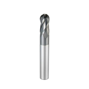
Why Micro End Mill Bits Break Prematurely When Machining Steel
After inspecting thousands of returned broken cutters and running extensive cutting tests, we found that over 90% of micro-tools do not reach normal wear limits. Instead, they snap suddenly without warning. When cutting steels like P20, H13, or 4140, operators often assume the cutting speed was too aggressive or the carbide grade lacked hardness. However, micro-geometry makes these tools exceptionally sensitive to subtle setup errors that standard cutters easily tolerate.
The thin core diameter of small-diameter steel end mill bits drastically reduces its bending resistance. When cutting forces exceed critical thresholds or experience sudden impacts, breakage happens in milliseconds. To solve this, we must evaluate the entire machining system—the spindle, holder, cutter, and chip evacuation method. Through years of on-site troubleshooting, we have identified three primary causes behind premature tool failure.
Runout Kills: The Hidden Impact of Tool Holders on Micro End Mill Bits
A radial runout of 0.008mm (8 microns) might only cause minor surface finish issues on a standard 6mm cutter. However, for 0.5mm micro end mill bits, that same runout spells immediate disaster. While troubleshooting a 316L stainless steel job for a medical manufacturing client, we discovered their standard ER collets had 0.01mm static runout. At high RPMs, a single flute bore over 80% of the workload, overloading the edge and triggering instant tool fracture.
For small-diameter steel machining, we recommend keeping Total Indicated Runout (TIR) under 0.003mm at the tool tip. Standard ER collets struggle to maintain this precision over time due to taper wear and embedded micro-debris. Upgrading to high-precision shrink-fit or hydraulic holders paired with precision-ground collets offers the most cost-effective way to extend tool life without buying more expensive cutters.
Chip Packing and Re-Cutting in Small Flute Volumes
Steel chips are inherently tough and gummy, while small-diameter flutes offer very limited chip pocket space. When slotting or machining deep pockets, failure to evacuate chips instantly causes fine steel debris to pack tightly inside the flutes. The rotating tool then forcefully compresses and re-cuts these hardened chips, generating extreme instant forces that quickly exceed the fracture toughness of any carbide end mill bit.
Our workshop testing shows that chip re-cutting typically leaves clear tensile fracture marks along the cutting edge. Relying solely on flood coolant often worsens chip packing because fluid surface tension traps fine chips inside tight cavities. Combining high-pressure dry air (above 0.6 MPa) with Minimum Quantity Lubrication (MQL) rapidly blasts fine chips out of the flutes, keeping the cutting zone clear and preventing catastrophic breakage.
Deflection and Bending Moment Under Excessive Radial Depth of Cut
Many CNC programmers apply standard roughing logic—large radial depth of cut (Ae) with shallow axial step-down (Ap)—to small cutters. However, this approach creates excessive lateral bending stress on high length-to-diameter (L/D) tools. Even micron-level tip deflection alters the effective rake angle, inducing chatter and concentrating severe stress at the neck transition until the cutter snaps.
To eliminate tool deflection when using end mill bits for steel, invert your cutting parameters by adopting trochoidal toolpaths or light radial, deep axial passes. Restricting radial width (Ae) to 2%–5% of the tool diameter while increasing spindle speed and feed rate reduces side-load forces by over 70%. This strategy ensures smooth, chatter-free cutting even on high-hardness steels.
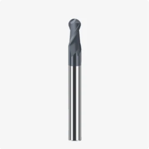
Calculating Speeds and Feeds for Steel End Mill Bits Below 1.0mm
Setting cutting parameters for small-diameter tools (under 1.0mm) is a true test of a CNC programmer’s expertise. Many technicians apply handbook formulas directly or linearly scale down parameters from larger tools, which usually leads to immediate tool breakage. As tool diameters shrink below 0.8mm, material cutting resistance at the microscopic level increases significantly, making traditional cutting models far too idealized for real-world production.
For micro-diameter steel end mill bits, parameter selection is not about chasing maximum metal removal rates. It is about finding the sweet spot that balances productivity with predictable tool life while preventing fatigue failure. We must dynamically adjust surface feet per minute (SFM), feed per tooth (FPT), and cut depths based on material hardness. Here is the real-world speeds and feeds logic we rely on in our factory.
Target Surface Feet Per Minute (SFM) and RPM Selection for Steel End Mill Bits
Selecting the correct surface speed (SFM) is the first step in managing cutting heat when milling alloy steels like 4140, P20, or H13. Small-diameter tools theoretically require extremely high RPMs to reach recommended SFM values, but most shop spindles cap out between 20,000 and 40,000 RPM. Blindly pushing spindle limits to match theoretical SFM often causes severe frictional heat, rapidly annealing the tool tip.
When machining HRC45 alloy steel, we recommend setting cutting speeds conservatively between 30 and 50 m/min (approx. 100–165 SFM). If your spindle is capped at 24,000 RPM, a 0.5mm carbide end mill bit may only run at 38 m/min, which is perfectly acceptable. Maintaining high dynamic spindle stability prevents sudden torque fluctuations, significantly extending effective tool life.
Feed Per Tooth (FPT) Thresholds for Solid Carbide End Mill Bit Micro Geometry
Managing feed per tooth (FPT) requires extreme precision. Micro-tools feature a small edge hone (1 to 3 microns) to prevent chipping. If the FPT is set smaller than this edge radius, the tool rubs and burnishes the steel instead of cutting, generating intense heat. Conversely, setting the FPT slightly too high exerts excessive cutting forces that instantly snap the delicate tool body.
When using a 0.5mm solid carbide end mill bit on 42CrMo (HRC38), we recommend maintaining an FPT between 0.001mm/t and 0.003mm/t. At 30,000 RPM with a two-flute tool, a feed rate of 120 to 180 mm/min provides a safe, reliable baseline. A feed adjustment of just 0.0005mm/tooth determines whether a tool runs smoothly for hours or snaps in seconds.
Micro Step-Down (Ap) vs Step-Over (Ae) Ratio for High-Hardness Steels
When slotting or profiling hardened steels (HRC50–HRC58), the ratio between axial depth of cut (Ap) and radial step-over (Ae) determines tool survival. Traditional parameters—large radial engagement (Ae = 30%D) paired with shallow axial passes (Ap = 2%D)—concentrate massive loads onto the fragile tip radius, causing rapid wear and catastrophic chipping.
For high-hardness steel, we recommend a “golden ratio” using a micro radial step-over paired with a moderate axial step-down. Keep Ae between 2% and 5% of tool diameter while increasing Ap to 10%–20%D. This distributes cutting heat along a longer section of the edge, reducing side load and enabling micro end mill bits to achieve high-quality mirror finishes.

Shop-Floor Best Practices to Prevent Breaking Micro End Mill Bits for Steel
Theoretical parameters are only the starting point; actual tool longevity depends heavily on daily shop-floor habits. Engineers often design clean CAM toolpaths, only for the operator to break the tool upon entry due to a misplaced coolant nozzle or aggressive plunge. Most instances of premature failure can be completely avoided by optimizing Standard Operating Procedures (SOPs).
Operators must treat micro-tools with far greater care than standard 10mm or 12mm cutters. Managing shop-floor success requires controlling thermal shock, minimizing entry impact, and establishing proper tool-pass transitions. Through years of machine setup and customer support, we have established a clear set of practical rules to reduce abnormal wear on end mill bits for steel.
Air Blow vs. MQL: Coolant Delivery for Micro End Mill Bits for Steel
Using high-volume flood coolant on steels like P20, H13, or SKD61 frequently triggers severe thermal shock on micro-tools. As the tiny carbide tip rapidly cycles between the hot cutting zone and cold fluid, microscopic thermal cracks form along the edge, causing unexpected chipping. On-site testing confirms that small-diameter tools suffer significantly higher breakage rates under flood coolant than under dry airflow.
A far better approach combines a high-pressure dry air blast (above 0.6 MPa) with Minimum Quantity Lubrication (MQL). The compressed air rapidly clears fine, hot chips out of narrow flutes to prevent chip re-cutting, while the MQL oil mist reduces friction. For small-diameter china end mill bits for steel factory applications, prioritizing clear chip evacuation over flood cooling dramatically improves tool stability.
Tool Setter Calibration and Soft-Entry Strategies into Hardened Steel
Tool setting is the first major obstacle in micro-machining. Traditional mechanical touch-setters or block gauges apply downward contact forces that easily exceed the elastic limit of micro-shanks, damaging edges before the spindle even turns. Micro-tools should always be set using non-contact laser systems or high-precision optical presetters calibrated to within 1 micron to guarantee accurate height and minimal runout.
Additionally, entry impact forces frequently break small tools when engaging hardened stock. Straight vertical plunging or steep ramping should be strictly avoided in favor of shallow ramp angles (1° to 2°) or pre-drilled pilot holes. Implementing a “soft entry” feed reduction (30%–50% of nominal feed for the first 0.2mm of engagement) effectively eliminates destructive entry shocks.
Pairing Micro Tools with HRC55 Ball Nose End Mill Bits in Mold Machining
Relying on a single tool size for deep-cavity mold machining makes it difficult to balance efficiency with corner-clearing precision. When micro-tools directly engage heavy, uneven stock left by previous roughing passes, sudden load spikes instantly snap the cutter. A stepped tooling strategy removes stock in uniform layers, creating a safe, highly controlled cutting environment for smaller tools.
In typical mold workflows, robust hrc55 ball nose end mill bits perform the semi-finishing passes first, leaving a uniform 0.01mm to 0.02mm stock allowance in tight corners. Micro ball-nose or flat cutters are then introduced purely for final corner clearing and fine detailing. This stepped transition uses larger tools to pave the way, ensuring safe cutting loads and maximum process reliability for micro-cutters.
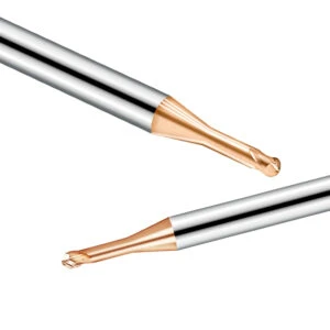
Manufacturing Standards at Our Factory for Steel Cutting Micro End Mills
European and American machinists frequently raise the same concern: batch-to-batch inconsistency when sourcing tools from overseas, leading to unpredictable tool life on steels like P20, H13, or D2. For tools under 1.0mm, even micron-level stock runout or minor edge nicks lead to immediate breakage and scrapped parts. That is why our facility focuses entirely on maintaining micron-level tolerance control across every manufacturing stage.
Producing reliable cutters for hardened steel involves far more than simply running a grinding machine. The process requires ultra-fine carbide grain selection, precise substrate heat treatment, in-process 5-axis compensation, and rigid nano-coating adhesion control. Enforcing strict inspection protocols at every step provides the quality foundation needed to support precision machine shops worldwide.
Sub-Micron Carbide Substrates for High Hardness Steel Micro End Mills
Machining steel requires extreme hardness to resist abrasive wear and high fracture toughness to withstand micro-vibrations. Conventional substrates often suffer from intergranular fracture on steels exceeding HRC50 due to uneven cobalt distribution. We strictly select ultra-fine grain carbide rods (<0.4 µm) that maintain hardness above HRA 93.5 with exceptional transverse rupture strength (TRS ≥ 4000 MPa), ensuring our micro end mill bits resist both wear and brittle fracture.
Edge passivation and coating quality further define tool performance. Untreated ground edges feature microscopic jagged defects that trigger instant chipping under load. After grinding, we passivate edges to a 2–4 µm radius and apply an AlTiSiN nanocomposite coating. This heat-resistant coating withstands oxidation up to 1100°C, blocking cobalt diffusion wear during high-speed machining.
Tool Geometry Inspection and Concentricity Control in Our Factory
Producing small-diameter tools demands exceptional machine rigidity and strict climate control. In our shop, all cutters are ground on 5-axis CNC grinders from Rollomatic and ANCA inside a climate-controlled room kept at 20°C ± 0.5°C to prevent thermal expansion. Integrated laser diameter measurement and automatic compensation systems keep diameter tolerances within 0 to -0.005mm and concentricity under 0.002mm.
Ground tools must pass microscopic optical inspection on German Zoller or Helicheck presetter units before coating. Key attributes—including helix angle tolerance, relief flatness, and flute surface finish—are meticulously verified. As an established china end mill bits for steel factory, we immediately reject any batch showing flute grinding marks, knowing poor flute finishes impede chip evacuation and trigger tool failure.
Tailored Tooling Solutions from a Chinese Supplier of Steel-Cutting End Mills
Standard catalog cutters often struggle with deep cavities or complex part geometries. When clearing deep corners with high length-to-diameter ratios (L/D ≥ 10), standard tools frequently lack the necessary neck clearance or rigidity. As a manufacturer with integrated R&D, we specialize in solving custom application challenges by rapidly engineering extended neck clearances, reinforced tapered shanks, or variable flute geometries.
For example, we customized D0.8mm variable-helix cutters for a North American client machining HRC52 mold steel deep cavities. By optimizing the neck transition radius, we boosted bending stiffness by 35%, allowing the shop to double machining feed rates while maintaining surface finish specs. A reliable carbide end mill bit supplier must act as an extension of your engineering team to overcome tough machining bottlenecks.
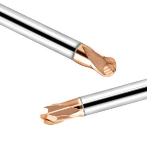
Troubleshooting Guide for Common Steel End Mill Bit Failures
When a micro-tool breaks on the shop floor, tossing it into the scrap bin without inspection is a missed learning opportunity. Wear patterns and fracture faces provide direct feedback about spindle runout, chip re-cutting, thermal shock, or excessive entry impact. Learning to read these failure marks allows CNC engineers to move from guessing parameters to establishing repeatable, stable machining processes.
Micro-tool failures on pre-hardened (HRC40) or hardened (HRC55+) steels rarely happen at random. Cross-referencing physical edge damage against your feed rates, chip clearance methods, and holder rigidity helps pinpoint root causes. Combining proper diagnostics with structured parameters ensures your steel end mill bits deliver reliable cutting performance.
Diagnosing Micro Tool Chipping vs Catastrophic Snap Breaking
Troubleshooting begins by distinguishing edge micro-chipping from catastrophic shank breakage. Tiny, localized nicks on the tip radius usually indicate high-frequency impact or thermal stress concentration. If micro-chipping occurs on hardened steel, check for thermal shock caused by flood coolant, switch to a shallow ramp-entry strategy, and verify that feed per tooth does not exceed the edge hone radius.
Conversely, an abrupt snap at the shank transition radius indicates severe overload fracture. Check total system runout (TIR) with a dial indicator to ensure it remains under 0.003mm, and verify that packed chips are not causing re-cutting. Reducing radial engagement (Ae), adopting high-frequency shallow passes, and using high-pressure air blasts eliminate the bending stresses that cause sudden tool snaps.
Adjusting Machining Parameters for Extended Steel End Mill Bit Tool Life
Maximizing tool life requires dynamically adjusting parameters based on observed wear patterns rather than relying on fixed settings. Healthy tool wear appears as uniform flank wear. If you notice rapid flank wear accompanied by friction noise, the tool is likely rubbing due to excessive surface speed or insufficient feed per tooth. Lowering spindle speed by 10%–15% or slightly increasing feed helps the edge bite cleanly into the material.
When clearing tight corners with hrc55 ball nose end mill bits or cutting thin-walled steel pockets, static charts may fall short. If adjusting speeds, feeds, and entry strategies fails to resolve short tool life, share your part prints, hardness specs, and holder setups with us. Fine-tuning clearance angles, upgrading carbide grades, or applying custom coatings will stabilize your process and prevent premature tool breakage.






