


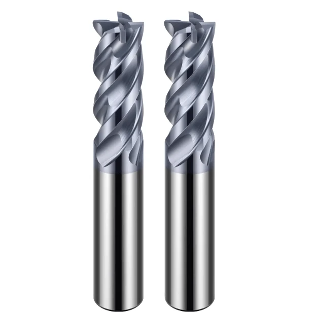
In machine shops across Europe and the Americas, the most common urgent calls our technical support team receives aren’t about tool wear, but rather that piercing, high-pitched shriek: harmonic chatter.
Last month, a precision manufacturing client in the U.S. Midwest reached out to us while batch-processing 4140 alloy steel hydraulic valve blocks (HRC 32) on a 3-axis machining center. Though running an industry-standard 4 flute solid carbide end mill, severe vibrations echoed throughout their shop during side milling. This issue left heavy, wavy chatter marks on the workpiece surface and caused premature micro-chipping on the cutting edges after machining fewer than three parts.
This scenario is all too familiar to us. Over the past 15 years as a dedicated manufacturer of solid carbide end mills, we have helped countless machinists resolve these frustrating harmonic issues. Often, an operator’s first instinct is to dial back the spindle speed or feed rate, but this intuitive move frequently backfires, pushing the tool deeper into a destructive resonant frequency range.
When milling tough alloys—especially during high-efficiency profiling with specialized carbide end mills for steel—chatter is a self-excited resonance between the spindle, holder, workpiece, and cutter. Steel’s high elastic modulus makes it highly sensitive to cutting force fluctuations. Whether using a flat-bottom cutter for heavy roughing or solid carbide ball nose end mills for 3D mold finishing, resonance erupts the moment the micro-mechanical balance between tool overhang, cutting depth (Ap), width (Ae), and chip load is disrupted.
Is your shop currently battling this persistent, high-pitched squealing noise—forcing you to back off on your machining efficiency just to save your surface finish?

16 Years of Shop-Floor Diagnostics: Why Do Your Carbide End Mills for Steel Experience Abnormal Chatter?
Over our 16 years of serving B2B clients in Europe and the Americas, our first diagnostic step is always to visit the site, listen to the cut, and examine the chips. When faced with a high-frequency squeal while milling stainless or tool steel, many shops habitually blame poor tool quality. However, our tracking data reveals that tool defects cause less than 15% of chatter; the vast majority stems from microscopic force imbalances within the overall machining setup.
When standing at the machine, seeing chips turn into powder instead of coming off in clean, golden-yellow or blue segments indicates that your setup is trapped in a resonance loop. This frustrating phenomenon is incredibly common when using carbide end mills for steel on medium-to-high hardness alloys. To root out this efficiency killer, we must shift our focus from the control panel down to the microscopic interface where the tool tip meets the material.
Insufficient Rigidity and Amplitude Resonance: A Micro-Geometric Perspective on Solid Carbide End Mills
In our tool design and testing centers, engineers frequently encounter a classic machining paradox: in a blind pursuit of chip clearance, some shops select tools with excessively small core diameters, severely compromising rigidity. When a solid carbide end mill engages with 4140 or P20 steel, the cutting edges endure severe, periodic impact forces. If the core diameter is too small, the tool body deflects under radial forces, initiating the vibration amplitudes that trigger chatter.
Furthermore, standard symmetrical flute designs cause each cutting edge to engage the workpiece at identical time intervals under a constant spindle speed. This uniform mechanical impact easily aligns with the natural frequencies of your setup, escalating into uncontrollable self-excited resonance. When troubleshooting on-site, we often suggest switching from standard symmetrical designs to high-performance, variable-geometry tools to disrupt these harmonic cycles.
A Common Mistake by Western Buyers: Mismatch Between Cutting Parameters and Material Hardness
In discussions with senior programmers across Western shops, we often see them fall into the trap of blindly adopting recommended parameters from general handbooks. Last quarter, a German client machining 316L stainless steel attempted to meet a tight deadline by setting a high spindle speed coupled with an extremely low feed per tooth. While they intended to reduce tool load, the result was catastrophic high-frequency chatter that destroyed the tool in under ten minutes.
Our parameter database shows that this “high speed, low feed” setup is disastrous for steels prone to work hardening. When the feed per tooth drops below the edge honing radius, the cutting edge stops shearing the metal and instead “skids” across and compresses the surface. This intense friction generates excessive heat and forces your speeds and feeds outside the stable stability lobes. In these scenarios, our go-to fix is actually counter-intuitive: we reduce the cutting speed and aggressively increase the feed rate.
The Hidden Impact of Toolholder Clamping Systems and Spindle Runout on Steel Machining
When troubleshooting chatter, many operators focus exclusively on the cutter and the program, completely overlooking the critical bridge of force transmission: the toolholder. We once resolved a baffling case in Ohio where identical tools and parameters worked beautifully on one machine but shook the foundation of an identical machine next to it. Upon checking the troublesome machine’s spindle bore and heavy-duty collet with a dial indicator, we discovered a radial runout of 0.025 mm.
In high-speed steel milling, a runout error of just 0.01 mm is exponentially amplified by the high elastic modulus of the material. As a 4 flute solid carbide end mill rotates with high runout, one specific cutting edge bears a load far exceeding the other three, creating a severe cyclical force imbalance. This hidden issue—often caused by fatigued ER collets or spindle bearing wear—instantly triggers chatter and premature edge chipping. Before changing your program, we highly recommend switching to high-precision hydraulic or shrink-fit holders to isolate the variable.
Practical Parameter Adjustment: Eliminating Chatter When Using 4 Flute Solid Carbide End Mills by Optimizing Speeds and Feeds
When a high-frequency screech echoes through the shop, many operators instinctively hit the emergency stop and blindly lower the spindle speed. However, in our experience, blind parameter adjustments lacking quantitative data rely merely on luck. To truly tame severe chatter when milling steel, the most direct and effective method is to optimize your speeds and feeds, disrupting the resonance equilibrium to restore a stable cutting state.
As technical support specialists, we spend hours beside machining centers, fine-tuning parameters based on chip formation and spindle load feedback. This process is particularly critical when running a standard 4 flute solid carbide end mill on alloy steel exceeding HRC 35. Those four cutting edges guarantee high metal removal rates but also act as potential sources of harmonic vibration if cutting forces are not kept within the machine’s rigidity limits.
Fine-Tuning Rules for Surface Speed (SFM) and Feed Per Tooth (IPT) for 4-Flute Solid Carbide End Mills: Dynamic Milling vs. Traditional Side Milling
Modern CAM toolpaths impose vastly different mechanical demands on your cutter depending on whether you employ dynamic milling or traditional heavy-duty side milling. During traditional side milling, the large radial contact arc causes cutting heat to accumulate rapidly at the cutting edge, requiring a conservative surface speed (SFM). In this scenario, the feed per tooth (IPT) is crucial: if the chip load is too light, the tool will rub against the work-hardened layer, triggering intense high-frequency chatter.
When switching to high-efficiency dynamic milling paths, the minimal radial engagement (Ae) allows the tool body more time to dissipate heat. While you can safely increase your SFM, you must account for the chip thinning effect and adjust your feed rate upward. Neglecting this compensation results in light cutting forces that fail to stabilize the cut, causing micro-chipping on the solid carbide end mill. Increasing the actual feed by 1.5 to 2 times allows the thicker chip to effectively dampen vibration.
The Golden Ratio of Axial Depth of Cut (Ap) to Radial Width of Cut (Ae): Maximizing Chatter Suppression in Steel Machining
When troubleshooting shop-floor harmonics, we often find programmers falling into the trap of using “shallow roughing” strategies with large radial widths (Ae) and small axial depths (Ap). From a mechanical perspective, excessive radial width directs the bulk of the cutting resistance straight onto the spindle’s radial axis—the exact direction where machine rigidity is weakest. If you are using carbide end mills for steel to mill deep slots, this excessive radial loading inevitably leads to deflection and severe chatter.
To maximize chatter suppression, we recommend a “golden ratio” of large axial depth (Ap) and small radial width (Ae) during process optimization. Try increasing the axial depth of cut to 1.5 to 2 times the tool diameter while keeping the radial width to approximately 10% of the cutter diameter. This approach directs the cutting forces toward the spindle’s axial direction—the axis of maximum machine rigidity—while engaging more flute length to distribute cutting forces evenly and dissipate harmonic energy.
Real-World Troubleshooting Cases with European and American Clients: “Lower Speed, Higher Feed” vs “Higher Speed, Lower Width of Cut”
Last year, an Italian component plant encountered severe low-frequency vibration while machining 4340 high-strength alloy steel. Their initial setup of 120 SFM and a 0.04 mm chip load caused the entire machine table to shake violently. Instead of reducing the feed, we decisively adopted a counter-intuitive “lower speed, higher feed” strategy, dropping the spindle speed by 20% while boosting the feed per tooth to 0.07 mm to thicken the chips and stabilize the cut.
In another case involving precision tool steel in the UK, the previous method failed because the setup had excessive workpiece overhang and poor fixture rigidity. We immediately switched to a “higher speed, lower width of cut” strategy, cutting the radial width (Ae) in half and compensating by increasing the spindle speed by 30%. This broke up the impact energy of each cut, successfully avoiding the fixture’s natural resonant frequency. Have you ever tried breaking free from handbook parameters to find a solution when faced with a similar impasse?

Machining Complex Surfaces and Mold Steel: Process Solutions to Eliminate Squealing and Chipping with Solid Carbide Ball Nose End Mills
In mold manufacturing and 3D profiling, the most troublesome issue during semi-finishing is the piercing squeal that occurs at steep-to-shallow surface transitions. This high-frequency vibration is often accompanied by micro-chipping of the cutting edge, which can instantly ruin an expensive cutter and damage a mold cavity that has already undergone dozens of hours of machining. When addressing these steel mold challenges, we focus primarily on the dynamic changes in the contact arc.
The root cause of frequent squealing and edge failure lies in the unique spherical geometry of ball-nose cutters. During profile milling, the tool’s active cutting zone constantly slides along the spherical arc. Without dynamically compensating your parameters based on the actual depth of cut, the near-zero cutting speed at the center of the ball causes intense rubbing and heat, making it crucial to re-evaluate solid carbide ball nose end mills using both cutting mechanics and thermal dynamics.
Speed and Feed Compensation Calculations for Near-Zero Center Cutting Speeds in Profile Milling
During on-site troubleshooting, we observe many programmers calculating spindle speeds using the tool’s nominal diameter (Dm). For instance, when using a 10mm ball nose cutter on shallow slopes, only the section of the ball near the central axis is actually engaged. Geometrically, the radius of rotation at the center of the ball approaches zero, meaning your actual cutting speed (Effective SFM) at the point of contact is virtually zero.
At such low speeds, the cutting edge fails to shear material, causing violent squeezing and tearing that leads to spindle load fluctuations and severe chatter. To resolve this, our technical protocols mandate calculating the true effective cutting diameter (Defe) based on the actual axial depth of cut (Ap). This allows you to significantly increase the spindle speed, ensuring the ball center maintains an optimal cutting speed range so the solid carbide end mill performs clean shearing rather than merely wearing down.
Adjusting Ball Nose End Mill Feed Rates for HRC 45–60 Hardened Mold Steels to Prevent Thermal Shock and Chatter
Machining hardened tool steels exceeding HRC 50 presents severe challenges. During the finishing stages of these hard materials, operators often adopt overly conservative feed rates out of fear of edge chipping. However, an excessively low feed per tooth causes the cutting edge to slide violently against the hardened surface, generating intense friction and heat that concentrates at the tool tip. When coolant suddenly hits this red-hot tip, thermal shock creates micro-cracks, leading to sudden edge failure.
For these high-hardness applications, we prefer dry machining with a strong air blast and a calculated increase in the feed rate. We slightly increase the feed per tooth based on the required scallop height so that the chips carry away the majority of the cutting heat, preventing it from soaking back into the tool body. This fine-tuning enables the carbide end mills for steel to achieve stable shearing on the hardened surface, utilizing continuous chip evacuation for cooling. Have you ever experienced a drastic drop in tool life due to improper cooling when machining hardened steel?

Controlling Vibration at the Source: How High-Quality Solid Carbide End Mill Manufacturers Solve Resonance Issues in Steel Machining through Tool Design
Relying solely on on-site parameter adjustments is sometimes insufficient to overcome extreme chatter caused by poor workpiece rigidity or excessive overhang. As experienced solid carbide end mill manufacturers, we know that true vibration control must be addressed at the design source. By optimizing the tool’s physical geometry, we disrupt the periodic accumulation of cutting forces, effectively embedding inherent vibration resistance into the tool during the grinding stage.
During in-house R&D, our technical team utilizes dynamic simulation software to analyze the cutting force waveforms generated when the tool engages a steel workpiece. Conventional symmetrically designed cutters generate intense, regular periodic mechanical pulses during high-speed rotation. By making critical asymmetrical modifications to the cutting edge geometry, we break this resonance cycle, allowing our carbide end mills for steel to maintain exceptional stability under demanding conditions.
Disrupting Periodic Cutting Force Impacts with Variable Index and Variable Helix Designs
On our 5-axis grinding machines, Variable Index and Variable Helix geometries have become standard features for our high-performance steel machining tools. Traditional end mills feature uniform 90° angular spacing between flutes, resulting in a constant frequency of engagement with the workpiece. In contrast, our asymmetrical designs utilize fine-tuned, non-uniform flute spacing combined with a helix angle that varies gradually between 35° and 38°.
This geometry ensures that each cutting edge experiences a unique force profile during the machining process. As the 4 flute solid carbide end mill rotates at high speed, the timing of each flute’s engagement and the components of the helical cutting force are constantly shifting, effectively dispersing the harmonic pulses. Comparative cutting tests show that this variable-helix structure reduces the amplitude of dynamic cutting force fluctuations by over 30%.
The Critical Role of Edge Honing and Flute Polishing in Reducing Cutting Resistance
Many machine operators hold the intuitive misconception that a sharper cutting edge is always better. However, when machining high-strength steel, an excessively sharp microscopic edge is prone to instant micro-chipping under impact, triggering severe frictional vibration. Therefore, after precision grinding, we employ specialized equipment to perform micron-level edge honing, creating a micro-arc of 10 to 15 μm.
Beyond edge honing, the surface finish of the flutes plays a decisive role in cutting forces. We apply a secondary mirror-polish to the flutes, minimizing frictional resistance as steel chips are evacuated and preventing them from momentarily jamming. When chip flow becomes exceptionally smooth, instantaneous spindle load fluctuations stabilize, which is why high-quality solid carbide end mills deliver quieter performance and longer tool life.
As a Direct Manufacturer, How We Optimize Carbide Substrate Toughness Based on Feedback from European and American Clients
As a manufacturer dealing directly with overseas markets, we compile weekly technical reports from Western machine shops. We frequently observe tool breakage at the neck or shank junction during high-load, long-overhang roughing operations—a clear indication that the substrate lacks sufficient impact toughness. Tungsten carbide substrates designed solely for high hardness tend to be too brittle, leading to catastrophic failure under intermittent impact.
To overcome this, we collaborate with premium rod suppliers to adjust cobalt (Co) content and grain size distribution, striking an optimal balance between hardness and toughness. Furthermore, to address deep-cavity curved surfaces in mold making, we optimized our solid carbide ball nose end mills with a stepped-taper profile, nearly doubling their bending rigidity. When seeking machining solutions with long tool life, do you pay close attention to substrate microstructure?
Diagnostic Checklist: Our Process for Troubleshooting Abnormal Chatter During Steel Milling
After countless emergency interventions at client sites across Europe and the US, we know that blind experimentation is the worst approach when a machine is screaming on your shop floor. Randomly tweaking parameters without a logical plan not only fails to solve the problem but often obscures the root cause. To address this, our technical team has developed a standardized, step-by-step troubleshooting checklist to pinpoint steel milling harmonics in minutes.
When faced with stubborn vibration issues, try consulting this diagnostic checklist to shift your focus from mere tool quality to the entire machining system. From physical overhang and spindle force direction to the dynamic matching of cutting parameters at a microscopic level, every step brings you closer to the root cause. If you are using carbide end mills for steel, you can diagnose and solve the problem methodically using the three standard steps below.
Check for and Eliminate Bending Stress Caused by Overhang and Clamping Force
In our diagnostics, over half of all severe chatter issues stem from excessive tool or workpiece overhang. Bending rigidity is inversely proportional to the cube of the tool overhang length. If you extend a solid carbide end mill an extra 10mm—perhaps merely to avoid fixture interference—the radial deflection at the tool tip during steel machining will increase exponentially, amplifying runout and triggering high-frequency chatter.
If you are finishing deep cavities and must use a long overhang, start by examining the tool holder’s clamping method. Traditional collet chucks often lack sufficient clamping rigidity, making them prone to micro-slippage during heavy-load steel machining. We recommend switching to high-precision hydraulic or shrink-fit holders and retracting the tool shank as far as possible to cover at least 80% of the holder’s bore depth.
Use Specific Formulas to Reverse-Engineer and Adjust Speeds and Feeds Until Resonance Disappears
If the squealing noise persists after shortening the overhang, you must proceed to the mechanical recalibration of your cutting parameters. As previously analyzed, many machine operators habitually lower the spindle speed when chatter occurs, but this often distorts the feed-per-tooth and causes severe work hardening. If you are performing deep, narrow dynamic milling with a 4-flute solid carbide end mill, recalculate your actual feed-per-tooth by accounting for chip thinning.
At this stage, the key is to use the pitch of the chatter noise to guide your adjustments. High-frequency squealing usually indicates excessive spindle speed or an overly large radial depth of cut (Ae); try reducing the speed by 10 to 15% or reducing the cut width. Conversely, a low-frequency rumble suggests insufficient workpiece or fixture rigidity, meaning you should decisively lower speed while increasing feed to thicken the chips and suppress vibration.
Assessing the Need for Custom Non-Standard Cutting Edges from Solid Carbide End Mill Manufacturers
If you have exhausted all workholding optimizations and parameter adjustments but still cannot eliminate micro-chatter marks on ultra-deep slopes or hard steel, your standard tooling has reached its geometric limits. When facing these extreme conditions, it is worth considering custom non-standard solutions. Standard tools simply cannot cover every highly specialized variable on a challenging shop floor.
As professional solid carbide end mill manufacturers, we frequently customize variable-pitch and variable-helix cutting edges tailored to specific workpiece materials and cavity depths for our B2B clients. If your shop is currently grappling with a challenging steel project, or facing high tooling costs and scrap rates, please feel free to share your specific operating conditions, part drawings, or material grades with us so we can collaborate on a custom solution.






