


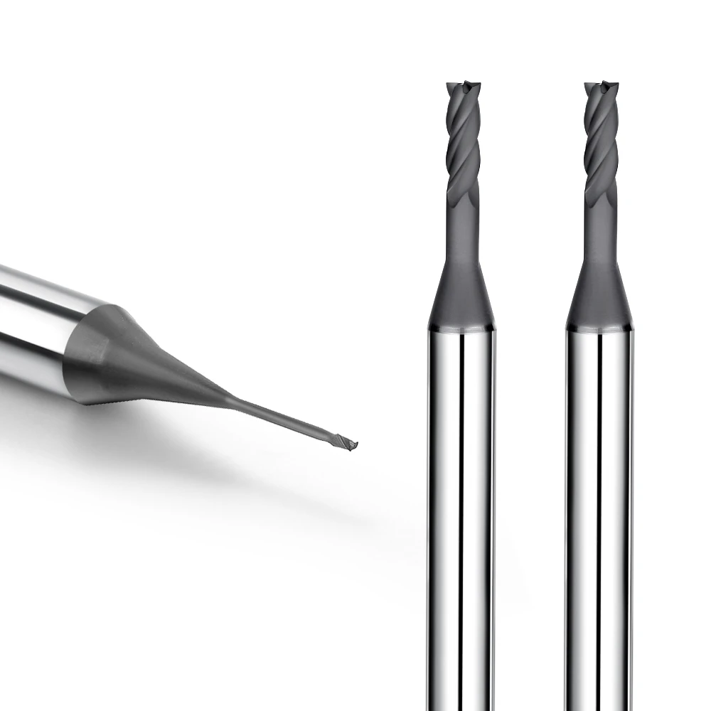
Over our 20 years in graphite machining, optimizing graphite end mill speed and feed settings has been a constant shop-floor challenge. We frequently help clients fine-tune these exact parameters to fix performance issues.
We recently assisted a precision mold manufacturer experiencing rapid tool wear while machining large graphite electrodes. Their new end mills started strong but quickly lost precision, causing edge chipping and poor surface finishes. While they blamed the tool quality, our analysis revealed the true cause: improper graphite machining parameters, particularly a mismatch between cutting speed, feed rate, and chip load per tooth.
Although graphite cuts easily, its abrasive, brittle, and dusty nature creates unique machining challenges. Applying standard speeds and feeds meant for aluminum or copper often accelerates graphite end mill wear and damages cutting edges. Successful machining requires a parameter strategy tailored specifically to graphite’s abrasive characteristics.
Optimizing your process means balancing tool diameter, flute count, depth of cut, material grade, and machine rigidity. During roughing, your focus should be high material removal rate (MRR) and tool durability. During finishing, the focus shifts to tight dimensional tolerances, smooth surface finishes, and edge integrity.
Through extensive shop-floor testing, we developed a practical framework for graphite milling speed and feed optimization. This system aligns tool specifications with ideal parameters to extend tool life, maintain quality, and stabilize production.
When you face premature tool wear or unstable machining quality, the tool material is rarely the only culprit. The real solution lies in mastering the balance between tool geometry and process parameters.
Graphite End Mill Speed and Feed Analysis: Why Do Cutting Parameters Determine Graphite Machining Quality?
Through decades of hands-on machining with graphite electrodes and precision molds, we have learned that poor surface quality is rarely a tool defect. It almost always stems from running incorrect speeds and feeds for specific material grades. For instance, when a mold manufacturer used identical settings across varying graphite densities, increasing depth led to rough surface finishes and premature tool failure because the parameters ignored material density changes and cutting stress.
We view cutting speed and feed rate as interdependent components of a stable machining system, not isolated variables. The correct parameter combination maintains constant tool engagement, minimizes cutting force spikes, and delivers superior surface finishes. We always optimize graphite machining parameters step-by-step, factoring in tool diameter, flute count, radial depth of cut, and machine rigidity rather than relying on generic handbook charts.
How Do Graphite Machining Parameters Affect Graphite End Mill Wear?
When investigating tool failure on the shop floor, we first check if the feed rate matches actual cutting conditions. We once solved a severe wear issue where a client experienced a fraction of expected tool life. On-site testing revealed an overly conservative feed rate, which forced the cutting edge to rub against abrasive graphite grains rather than shearing them, rapidly accelerating wear while trapping abrasive dust in the cut.
Tool life depends on more than just material hardness—it is dictated by speed, feed per tooth, depth of cut, and tool geometry working together. When troubleshooting accelerated graphite end mill wear, engineers should look beyond substrate quality. Check whether high friction, excessive heat buildup, or improper chip loads are destroying your cutting edges prematurely.
The Impact of Graphite Milling Speed and Feed on Cutting Stability
Adjusting graphite milling speed and feed directly impacts chatter, tool deflection, and dimensional accuracy during machining. During deep-cavity electrode work, running the spindle too fast with a light feed rate triggers micro-vibrations. This unstable cutting action breaks down the tool edge and generates ultra-fine graphite dust that clogs flutes and degrades the cutting environment.
We tailor speed and feed parameters specifically to each machining stage. Roughing requires aggressive material removal rates paired with strong edge support, whereas finishing demands lower chip loads for tight tolerances. For high-precision parts, balancing cutting velocity with smooth toolpaths is far more effective than forcing maximum spindle RPM.
How Do Improper Graphite End Mill Parameters Lead to Rapid Tool Wear?
A common shop-floor misconception is that soft materials like graphite allow for ultra-aggressive speeds and feeds. In reality, graphite’s extreme abrasiveness quickly punishes improper settings, especially on small-diameter tools or deep slotting passes. Flutes subjected to sudden impact loads suffer micro-chipping, which quickly degrades into total tool failure.
When a graphite end mill breaks or wears prematurely, evaluate the entire system—geometry, speeds, feeds, toolholder runout, and stepover amounts. In most cases, recalibrating speed, feed per tooth, and axial depth restores cutting stability and dramatically extends tool life without purchasing expensive specialty cutters.
Graphite Milling Parameter Optimization: How to Set Optimal Cutting Parameters?
In high-density graphite mold and electrode projects, parameter optimization is often the defining factor between profit and scrapped parts. We once helped a shop struggling with inconsistent tool wear across identical machining batches. Our shop-floor analysis showed that while their tooling was consistent, their programming strategy failed to adapt to material grade density variations and changing tool engagement levels across different machining stages.
Selecting optimal graphite milling parameters is never about hunting for a single magic number in a manual. Successful strategies balance tool geometry, machine rigidity, graphite grade, and clear process goals. For example, roughing requires aggressive material removal, while finishing demands flawless edge retention. By incrementally adjusting spindle RPM, feed rate, axial depth, and radial stepover, we create stable cutting processes that maximize tool longevity.
Graphite End Mill Speed Selection: How to Determine the Right Spindle Speed?
When auditing customer programs, we always begin by verifying that the spindle RPM aligns with the cutter diameter and flute profile. In one precision electrode project, an operator ran a small-diameter end mill at excessively high RPM to push productivity. Instead of faster output, the extreme surface speed created severe heat and friction, causing rapid cutting edge breakdown and dimensional drift.
Determining the ideal graphite end mill speed requires balancing tool diameter, graphite grain size, cut depth, and spindle runout. For small tools or deep-cavity work, prioritizing dynamic stability over maximum RPM produces far better results. A balanced spindle speed eliminates high-frequency chatter, protects sensitive tool coatings, and preserves fine geometry throughout the cut.
Graphite End Mill Feed Rate Optimization: How to Control Feed Rate and Chip Load?
Feed rate settings are frequently neglected in favor of spindle speed tweaks. However, controlling the chip load per tooth is what actually manages mechanical cutting forces. During a mold machining audit, we found an operator running an overly conservative feed rate. Instead of protecting the tool, the microscopic chip load forced the flutes to rub continuously, rapidly abrading the carbide edge through friction.
Optimizing speeds and feeds for graphite end mills requires balancing flute count, tool diameter, and engagement style. For roughing passes, higher feed rates ensure proper chip formation and efficient heat removal. For finishing passes, feed rates must be controlled to prevent visible tool marks and surface tearing on thin walls.
How Do Depth of Cut and Step-Over Affect Graphite Machining Performance?
Machining defects in graphite are often caused by poor axial depth of cut (Ap) and radial stepover (Ae) choices rather than incorrect feed rates alone. In deep-cavity electrode work, taking an excessive axial cut dramatically increases lateral deflection forces. Even premium diamond-coated end mills will vibrate, chip edges, or break under these excessive side loads.
When tuning graphite machining parameters, we divide axial depth and radial stepover by machining phase. Heavy stepovers drive high material removal during roughing, whereas light radial engagement during finishing reduces cutting resistance and prevents burring. Balancing cut depth with radial engagement yields far better tool life than pushing any single parameter to its limit.
The Impact of Graphite Milling Speed and Feed Parameters on Graphite End Mill Wear
In our extensive shop-floor experience with graphite electrodes and mold machining, unexpectedly short tool life is a constant challenge. We once worked with a client machining high-density graphite who saw wild lifespan variations from the same tool batch. Some cutters finished multiple workpieces smoothly, while others chipped after just a few hours. Comparing their process logs proved the batch wasn’t defective; the client simply failed to adjust speeds and feeds for changing cut conditions.
Achieving long tool life requires a precise balance between spindle speed and feed rate. These parameters directly govern cutting load, dust evacuation, and edge stability. When parameters mismatch real-world machining conditions, surface quality drops and graphite end mill wear accelerates rapidly. To prevent premature failure, we constantly tune parameters based on material density, cutter diameter, toolpath strategy, and machine stability.
How Does Excessive Cutting Speed Accelerate Graphite End Mill Wear?
A common shop-floor misconception is that maxing out spindle RPM always improves graphite throughput. In reality, running excessive surface speeds subjects carbide edges to severe high-frequency impact. Furthermore, high RPM intensifies the abrasive action of micro-graphite dust trapped in the cut, creating intense heat and rapidly grinding down the cutting edge.
When optimizing parameters, we never just lower RPM blindly; we recalibrate based on tool diameter, coating thickness, material hardness, and axial depth. For small-diameter tools or tight-tolerance mold cavities, smooth cutting action matters far more than maximum surface speed. If you face abnormal graphite end mill wear, immediately verify whether your cutting speed exceeds the physical limits of your setup.
Why Does Insufficient Feed Rate Reduce Graphite Milling Cutter Life?
Engineers often lower feed rates hoping to protect delicate end mills and reduce cutting resistance. However, an overly conservative feed rate prevents the cutting edge from engaging the material properly. Instead of shearing clean chips, the tool repeatedly rubs against the abrasive graphite surface, generating extreme friction that dulls the edge far faster than normal cutting forces would.
Extending the service life of graphite milling cutters requires maintaining a healthy chip load per tooth. A proper feed rate ensures clean shearing action while pushing abrasive graphite dust up and out of the flutes. Because optimal feed rates vary by tool diameter and flute count, applying generic handbook feeds across different cutters will consistently destroy tool life.
How Do Appropriate Parameters Reduce Edge Chipping in Graphite Cutting Tools?
Edge chipping in graphite machining is rarely caused by weak carbide grades. In most cases, improper parameters subject fragile cutting edges to severe impact loads. When machining deep slots or thin-walled graphite electrodes, sudden stock variations create sharp force spikes, causing micro-chipping that rapidly leads to catastrophic tool failure.
By fine-tuning graphite milling speed and feed parameters alongside engagement angles, we redistribute cutting forces to protect vulnerable corners. For precision work, prioritizing consistent tool loading over aggressive single-pass depth prevents edge breakdown while improving surface finish. Is your current edge chipping issue really a bad batch of tools, or are unstable cutting parameters destroying your edges?
Methods for Optimizing Key Parameters in Graphite Machining Systems
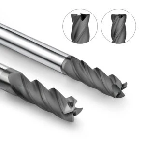
In our years of supporting graphite electrode and mold shops, we often discover that inconsistent results do not stem from bad cutters or poor stock. Instead, they happen because the overall system is out of alignment. We once worked with a shop running identical programs and tools on two different CNC centers. One machine ran smoothly for days, while the other suffered heavy vibration, dust buildup, and rough surface finishes.
Our shop-floor audit proved that cutting performance depends on how machine rigidity, spindle condition, workholding, speeds, feeds, and dust evacuation interact. When optimizing graphite machining systems, we evaluate every element together rather than tweaking isolated settings. Establishing a clear logic for full-system alignment is far more effective than constantly swapping tooling suppliers.
How to Match Speed and Feed in CNC Graphite Machining Systems
When fine-tuning process parameters, we first check whether the physical machine can actually support the programmed numbers. Operators often apply high-speed toolpath parameters directly from vendor catalogs without evaluating machine rigidity, spindle response, or controller look-ahead capabilities. This mismatch quickly causes excessive chatter and severe tool wear on the shop floor.
Modern CNC graphite machining demands dynamic parameter adjustments based on cutter diameter, graphite grade, and feature geometry. For instance, small end mills in deep mold cavities require conservative engagement to maintain stability, whereas large electrode roughing allows higher material removal rates. We always determine ideal parameters by running test cuts and analyzing real-time spindle load data.
The Relationship Between Machine Rigidity, Spindle Performance, and Graphite Machining Parameters
During site audits, we frequently observe identical parameters producing wildly different results on different machine tools. Clients often blame premature tool failure on aggressive speeds and feeds when the real culprit is poor machine rigidity. Micro-deflections in aging machine structures create severe cutting edge impacts that destroy carbide flutes prematurely.
Successful graphite cutting relies on stable spindle bearings, rigid castings, and high-precision toolholders. When balancing graphite machining parameters, we always tune settings to the machine’s actual condition rather than theoretical catalog maximums. Easing off cutting loads slightly often increases overall productivity by reducing costly downtime for tool changes and scrap rework.
The Impact of Cooling Methods on Graphite Machining Quality
Selecting the proper dust collection and air blast environment is crucial for consistent quality in graphite processing. Because graphite generates massive volumes of fine abrasive dust, keeping the cutting zone clear prevents double-cutting of trapped debris. We once resolved a precision electrode tolerance issue where heat and dust accumulation ruined dimensional stability over long run times.
Cooling and dust extraction methods must fit the specific process demands. High-precision electrode finishing requires high-volume vacuum systems to keep fragile ribs clear, while heavy roughing needs targeted high-pressure air streams to remove chips and dissipate localized friction heat. Optimizing dust management directly improves graphite machining quality while protecting tool edges. Is your current quality issue just a parameter problem, or is your entire system out of balance?
Selecting Graphite Milling Cutters: How Tool Geometry Affects Speeds and Feeds
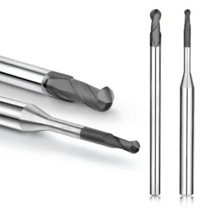
In our extensive work machining graphite electrodes, mold cores, and tight-tolerance components, we frequently see issues that parameters alone cannot fix. Clients often continuously adjust spindle speeds and feeds, yet tool wear, chatter marks, and edge chipping persist. Our shop-floor audits usually reveal the root cause: a fundamental mismatch between tool geometry and cutting conditions.
When selecting graphite milling cutters, we evaluate the entire machining setup—material density, feature geometry, cut depth, and machine rigidity. Flute count, helix angle, core thickness, and relief angles directly dictate chip clearance, cutting loads, and dynamic stability. We never set speeds and feeds in isolation; we ensure the cutter’s physical geometry can support the programmed loads.
Choosing Between 2-Flute and 4-Flute Graphite Milling Cutters
Clients frequently ask how to choose between 2-flute and 4-flute end mills for graphite. In one electrode project, a client ran a 4-flute graphite end mill at high RPMs through deep slots. The tight flute pockets quickly packed with abrasive dust, choking evacuation and accelerating wear. Switching to a tool design with flute capacity matched to the slotting depth instantly restored process stability.
Generally, 2-flute graphite end mill provide maximum chip gullet volume, making them ideal for heavy roughing, deep slotting, and rapid dust evacuation. Conversely, 4-flute designs offer greater core rigidity and more cutting edges, excelling at high-speed finishing where fine surface finishes are required. We balance chip load, cut depth, and finish requirements rather than assuming more flutes mean better productivity.
How Diamond Coated Graphite End Mills Enhance Machining Stability
During long production runs, standard uncoated carbide end mills suffer rapid abrasive wear and dimensional drift when cutting dense graphite grades. As the cutting edge dulls, cutting forces spike, ruining part consistency across batches. In these high-wear applications, deploying a diamond coated graphite end mill is essential for maintaining tight tolerances over long machining cycles.
CVD diamond coatings provide extreme surface hardness that resists abrasive dust, keeping cutting edges sharp and preventing thermal buildup. However, diamond coating is not a magic fix for poor setup. If core geometry, radial clearance, or cutting parameters are wrong, even premium diamond coatings will flake or chip. We always align coating selection with optimized tool geometry and proper feed rates.
How Do Different Graphite End Mill Geometries Align with Machining Parameters?
When troubleshooting graphite jobs, we always check if the tool geometry fits the cutting environment. Even among end mills of identical diameter, subtle variations in rake angle, primary relief, core diameter, and corner radius dramatically affect cutting forces. We often see dramatic performance improvements simply by matching tool structural features to specific toolpath strategies.
Properly pairing graphite end mill geometry with process parameters unlocks maximum cutting potential. For deep-cavity work, we prioritize heavy core strength and vibration damping; for thin-ribbed electrodes, we select sharp cutting edges with minimal radial force. Are your current parameter struggles truly a speed-and-feed issue, or is an improper tool geometry limiting your performance?
Enhancing Graphite Machining Quality: Improving Surface Finish through Parameter Optimization
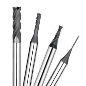
In our work with EDM electrodes, precision molds, and graphite components, achieving superior surface finish is a top priority. We once assisted a shop where finished graphite electrodes met strict dimensional tolerances but displayed severe feed lines, forcing costly hand-polishing. Our shop-floor inspection confirmed that the issue was not raw material quality, but rather running aggressive roughing parameters during final finishing passes.
Achieving excellent graphite machining quality requires balancing tool runout, toolpath strategies, finishing allowances, and cutting parameters. Fine-tuning these parameters eliminates micro-vibrations and stabilizes cutting-edge loads, resulting in smooth, uniform surface textures. Rather than adjusting parameters in isolation, we optimize the entire toolpath sequence to maximize surface consistency.
How Can Graphite Milling Parameters Reduce Machining Marks?
When troubleshooting visible surface lines on graphite parts, we first verify whether finishing feeds match radial stepover amounts. On one high-precision electrode job, a client noticed distinct, periodic feed marks across flat surfaces. Analyzing their process logs revealed an excessive feed per tooth paired with an overly aggressive radial stepover for their small-diameter tool.
Optimizing graphite milling parameters suppresses cutting force fluctuations that leave chatter marks on part surfaces. Reducing radial engagement, allocating a dedicated light finishing pass (0.002–0.005 inches), and using arc-in toolpaths dramatically improve final surface quality. However, lowering parameters indiscriminately inflates cycle times, so we always balance surface requirements with real-world shop productivity.
How Do Speed and Feed Affect Graphite Surface Finish?
Testing cutting strategies on customer shop floors shows that speed and feed adjustments directly dictate surface texture. In a mold electrode project, an operator boosted feed rates to meet tight production deadlines. While cycle times dropped, the heavy chip load caused visible tool marks and edge chipping along thin rib features.
Balancing cutting speed and feed rate is critical for a smooth graphite surface finish. Excessively high spindle speeds accelerate abrasive tool wear and trigger chatter, whereas excessive feed rates overload fragile cutting edges. During finishing passes, we prioritize dynamic cutting stability first, then incrementally increase feeds based on real-time surface finish measurements.
How Does Optimizing Graphite End Mill Parameters Reduce Machining Defects?
Analyzing common machining defects reveals that most problems stem from incorrect tool loading rather than cutter defects. When milling thin-walled electrodes, fine slots, or deep cavities, unbalanced cutting loads trigger edge chipping, wall taper, and uneven surface finishes, even when using premium diamond-coated cutters.
Adjusting graphite end mill parameters optimizes cutting dynamics between the carbide edge and the graphite workpiece. Matching spindle RPM to cutter diameter, tuning feeds to flute count, and controlling engagement depth prevent part deflection and edge break-out. Are your current surface finish issues really caused by defective material, or are misaligned parameters destroying your part quality?
Analysis of Practical Applications for Graphite End Mill Speeds and Feeds
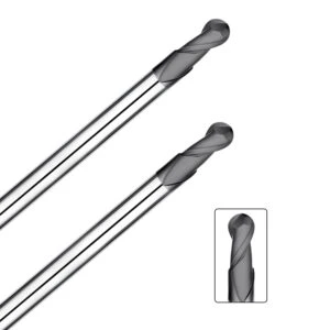
In our graphite machining projects, parameter selection is never a matter of copying a standard handbook table. Real-world performance requires custom adjustments based on workpiece geometry, material grade, cutter overhang, and machine rigidity. Even when using identical tool diameters on EDM electrodes versus mold inserts, parameter strategies vary wildly across roughing, semi-finishing, and finishing stages.
Understanding the core machining logic is far more valuable than memorizing static numbers. Roughing EDM electrodes demands maximum material removal rates and strong cutting-edge support, whereas machining precision molds prioritizes surface texture and tight tolerances. On the shop floor, we continually adjust graphite end mill speeds and feeds using real-time machine feedback to achieve the ideal balance between tool life and cycle time.
Experience with Speed and Feed Settings for Graphite Electrode Roughing
When roughing graphite electrodes, our primary goals are material removal efficiency and dynamic tool stability. In one project involving large EDM electrodes, an operator increased feed rates aggressively to shorten cycle times. However, the heavy stock allowance overloaded the cutter, triggering severe chatter and drastically reducing tool life.
When roughing high-stock graphite, verify tool diameter, axial depth, radial engagement, and machine rigidity before pushing feed rates. Rather than chasing maximum surface speed, we balance parameters to maintain steady cutting forces. Fine-tuning parameter combinations on-site helps manage varying graphite densities while preventing premature cutter breakage.
Parameter Optimization Methods for Graphite Mold Finishing
During precision graphite mold finishing, focus shifts to surface finish, dimensional stability, and crisp edge retention. We once resolved a case where a client suffered severe feed lines during mold finishing. Analyzing their setup revealed that while the end mill was sharp, their parameters still used heavy roughing logic rather than a dedicated finishing strategy.
Achieving pristine surface quality on high-density graphite molds requires optimizing feed rate per tooth, radial stepover, and toolpath engagement. We typically reduce cutting loads during finishing passes to minimize tool deflection and eliminate feed marks. Fine-tuning graphite milling parameters ensures exceptional surface finishes without sacrificing unnecessary machine time.
Tips for Adjusting Machining Parameters for Small Diameter Graphite End Mills
Machining micro-electrodes, deep ribs, and fine mold cavities with small-diameter tools creates unique breakage risks. End mills under 1/8 inch (3mm) have lower core strength and react severely to spindle runout, excessive tool overhang, and sudden chip load spikes. Standard parameters used for larger cutters will immediately snap these fragile end mills.
When running small diameter graphite end mills, always minimize tool overhang and verify spindle runout before setting feeds. We adjust spindle RPM, feed per tooth, and depth of cut incrementally, using test cuts and audible spindle feedback to find the sweet spot. Protecting delicate cutting edges ensures maximum tool life and precise detail reproduction.

FAQ: Graphite End Mill Speeds and Feeds
In our long-term support for shops cutting graphite electrodes, molds, and precision parts, engineers regularly ask about parameter selection, cycle efficiency, and tool longevity. Most facilities have excellent machines and tooling; what they lack is a clear strategy for adjusting speeds and feeds when switching between different graphite densities, tool sizes, and machining stages.
To help you troubleshoot your process, we compiled practical answers to common shop-floor questions regarding spindle RPM, feed rate control, tool wear mitigation, and cutter selection. For any machinist or programmer, mastering the engineering logic behind graphite end mill speeds and feeds is far more valuable than searching for a generic handbook formula.
What Is the Best Speed for Graphite End Mills?
Programmers frequently ask us for a single “magic RPM,” but ideal cutting speeds in graphite are dynamic. Determining the correct surface speed (SFM) depends on tool diameter, flute count, graphite grain density, depth of cut, and spindle runout.
When selecting the proper graphite end mills speed, align your RPM with your tool diameter and machining stage. Small micro-tools require high RPM balanced with strict vibration control, whereas large cutters require balancing metal removal rates with spindle load limits. On the shop floor, we always start conservative and fine-tune RPM based on real-time cutting sound and tool wear patterns.
What Feed Rate Should Be Used for Graphite Machining?
In our site audits, improper feed rate is the single most common cause of premature tool failure. Operators often drop feed rates drastically to “protect” fragile carbide edges. However, an excessively light feed forces the tool to rub rather than shear, creating intense friction that dulls the cutting edge far faster than normal cutting forces.
Establishing correct feed parameters requires calculating the proper chip load per tooth based on flute count, material grade, and axial depth. A healthy feed rate ensures clean shearing action and flushes abrasive dust out of the cut zone. Tailor your feed strategies separately for heavy roughing versus fine finishing passes.
How Do Graphite Machining Parameters Affect Tool Life?
When investigating premature tool wear or edge chipping, the root cause is rarely a defective cutter. Instead, misaligned graphite machining parameters—such as excessive surface speed, aggressive depth of cut, or poor ramping paths—subject fragile carbide edges to severe thermal and mechanical shocks.
Maximizing tool life requires a holistic approach that balances RPM, feed per tooth, stepover, and dust extraction. Before replacing a cutter brand, check whether your cutting parameters fit your specific graphite grade and machine setup. Fine-tuning these parameters routinely doubles tool life on customer shop floors.
Which Graphite Milling Cutter Is Suitable for High Speed Graphite Machining?
Selecting the right tool for high-speed paths depends on your specific part features rather than just buying the most expensive end mill. High-speed roughing and precision electrode finishing require tools engineered with optimized flute gullets, strong core rigidity, and high wear resistance.
For continuous high-speed machining, choose a graphite milling cutter with exceptional core strength and polished flutes for rapid dust evacuation. In high-volume production or abrasive graphite applications, upgrading to diamond coated end mills maintains razor-sharp edges and tight tolerances over long machining cycles. Align your tool selection with your machine’s spindle capability and target surface finish.






