


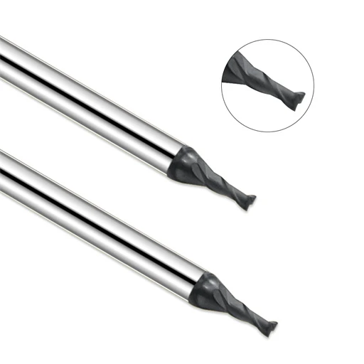
While helping a European client optimize their graphite electrode machining, we ran into a very typical issue. They were using the exact same graphite end mill across various electrode sizes. Despite adjusting feed rates, tool life stayed wildly unpredictable. Some tools lasted hours without issue. Others showed chipped edges and severe wear after cutting just a few cavity edges.
An on-site analysis revealed that tool quality was not the culprit. The real issue was a mismatch between the graphite end mill RPM and actual cutting conditions. Operators often focus heavily on feed rate, yet they overlook how spindle speed impacts chip discharge, cutting forces, and surface finish.
Over 20 years of supporting shop floors, we have seen this scenario time and again. Different material grades, tool diameters, cutting depths, and coatings all demand precisely matched parameters. A quick RPM adjustment directly rebalances your feed-to-speed ratio, protecting your cutting edges and stabilizing part quality.
Run your graphite end mill at an RPM that is too low, and cutting resistance spikes. This exposes fragile carbide edges to heavy mechanical shock. Conversely, excessive RPM produces abrasive graphite dust, accelerates edge wear, and ruins surface finish without proper geometry, cooling, and strategy.
We never answer with a single blanket RPM number. Instead, we evaluate tool diameter, flute geometry, helix angle, coating type, and overall machining goals. For instance, high-speed precision jobs demand diamond-coated graphite end mills to maintain sharp edges and withstand intense abrasion.
True cost savings in graphite machining do not come from maxing out spindle speed. They come from hitting the sweet spot between cutting tools, workpieces, and environmental controls. Have improper RPM settings ever caused unexpected tool failure or rough surface finishes in your shop?

Graphite Machining RPM Analysis: Why Does Graphite End Mill RPM Affect Machining Quality?
In our shop floor experience, spindle speed is often the most overlooked variable in graphite electrode production. We once audited a European mold maker struggling with inconsistent tool life across identical batches. Their team repeatedly adjusted feed rates and depths of cut, yet results varied wildly until our analysis revealed a clear mismatch between the graphite end mill RPM and their specific cutter diameter and material grade.
Because graphite is highly abrasive and brittle, rotational speed directly dictates your cutting dynamics rather than just cycle times. Setting an optimal graphite end mill RPM stabilizes cutting forces, minimizes mechanical shock, and speeds up dust evacuation. Relying on traditional metalworking speed formulas often leads to severe edge chipping, making parameter optimization essential for consistent part quality.
The Impact of Graphite Machining Speed on Cutting Performance
When tuning parameters for graphite electrode finishing, we tailor speed settings to match the exact operation goals. Heavy roughing requires a predictable cutting load to remove stock efficiently without stalling the spindle. Conversely, finishing passes demand higher, stable speeds to eliminate force fluctuations and prevent micro-chipping along delicate cavity walls.
Achieving superior surface finish requires balancing spindle speed with feed per tooth and effective chip load. Improper graphite machining speeds generate excessive vibration and trapped abrasive dust, even with high-end tooling. We always evaluate machine rigidity, spindle torque curves, and radial engagement before settling on a target RPM.
How Does Graphite End Mill RPM Affect Tool Wear?
We recently assisted a shop machining deep-cavity molds with micro-diameter end mills. Their tools wore out prematurely after just a few hours of operation. A quick audit showed they were running the graphite end mill at an excessively low RPM, forcing the cutting edge to rub against abrasive graphite grains rather than shearing them cleanly.
Tool wear stems from the complex interplay between RPM, chip load, and substrate coatings. Running too slow increases mechanical resistance and causes edge breakdown, while running too fast without adequate diamond coating generates destructive friction heat. Testing small speed increments helps machinists discover the ideal window for maximum tool longevity.
Causes of Graphite Edge Chipping and Surface Defects Due to Improper RPM
Corner chipping on thin-walled electrodes is a common nightmare for precision machine shops. Our field diagnostics reveal that edge breakout rarely stems from material flaws alone; it usually occurs when erratic cutting forces pass through fragile geometry. Unstable graphite end mill RPM settings amplify these forces right as the tool exits the cut.
Before swapping out expensive cutters, we always inspect parameter combinations and tool deflection first. Fine-tuning the RPM improves the edge-entry angle, dampens harmonic chatter, and lifts overall machining accuracy. For demanding electrode features, pairing optimized spindle speeds with diamond-coated tooling yields flawless surface finishes every time.
Calculating RPM for Graphite End Mills: How to Determine Optimal Graphite Cutting Parameters?
Field engineers frequently ask us for a single magic spindle speed when optimizing electrode production. In reality, handing out a fixed number rarely solves actual machining challenges. We once worked with a shop running identical-diameter cutters across varying cavity depths, only to suffer severe quality swings. Our audit showed their issues stemmed from an unbalanced relationship between spindle speed, feed rate, and mechanical load.
Determining ideal graphite cutting parameters requires evaluating the entire machining system rather than pushing speeds blindly. Because graphite is highly abrasive and brittle, the right speed-to-feed ratio dictates dust evacuation, cutting stability, and tool life. We always balance machine rigidity, tool geometry, and material grade to establish a reliable baseline before making micro-adjustments.
The Relationship Between RPM, Feed Rate, and Cutting Speed in Graphite Machining
Spindle speed, feed rate, and surface footage work as a synchronized triad during electrode milling. Operators often focus strictly on pushing feed rates, forgetting that changing your RPM instantly alters the chip load per tooth. Increasing spindle speed without adjusting table feed thins out the chip, leading to tool rubbing and accelerated edge breakdown.
When developing parameter strategies, we adjust settings based on flute count, graphite grade, and machining stage. Roughing passes prioritize high material removal rates under a stable load, whereas finishing passes demand sustained graphite end mill speeds to secure flawless surface finishes. Balancing these variables eliminates harmonic vibration and protects delicate cutting edges.
How to Calculate the Appropriate Spindle Speed Based on Graphite End Mill Diameter?
Recalculating spindle speeds for different tool sizes is essential when machining intricate mold details. Relying on generic formulas often fails because micro-tools (0.5mm to 1mm) behave differently than larger 6mm+ cutters. Choosing the right graphite end mill RPM based on tool diameter directly determines whether your cutter survives the first pass.
Smaller tools require higher rotational speeds to achieve effective cutting action, while larger cutters demand lower RPM to avoid excessive peripheral heat and tool wear. In our experience, calculating optimal speeds requires factoring in gauge length, tool stick-out, cavity depth, and machine spindle limits, rather than depending on a basic diameter formula.
How Do Graphite Machining Speed and Feed Rates Jointly Affect Machining Quality?
Through years of shop floor support, we have found that most machining defects stem from an unbalanced speed-to-feed ratio. For example, boosting feed rates to cut cycle times without increasing RPM leads to tool chatter, deep machining marks, and severe corner chipping. Proper alignment of these parameters guarantees stable chip evacuation and consistent dimensional accuracy.
For high-precision graphite machining, we recommend locking in a stable RPM range first, then gradually tuning your feed rate and axial depth of cut. Evaluating live cutting performance helps lock in the optimal sweet spot. Though this testing takes time upfront, it eliminates costly rework and frequent tool changes down the road.
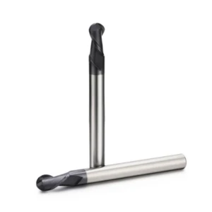
Optimizing Graphite End Mill Speed: How to Select RPM Parameters Based on Tool Diameter?
During on-site audits, we frequently spot shops using identical parameter sets across vastly different tool diameters. One client suffered constant micro-tool breakage in small cavities while struggling with low efficiency on larger cutters. Reviewing their machine logs showed that the root cause was not tool quality, but a failure to recalibrate their graphite end mill speed for each tool diameter.
Optimal spindle speed is never a static number; it must adapt to tool diameter, flute count, stick-out length, and material density. Different tool sizes experience vastly different cutting loads and peripheral speeds. Before setting your parameters, we recommend analyzing cutter geometry and machining goals to establish a stable, repeatable process.
RPM Setting Strategies for Small Diameter Graphite End Mills
We frequently engineer processes for miniature tools (0.3mm to 1mm) to machine fine detail in precision electrodes. While micro-cutters deliver exceptional detail, their delicate cross-sections offer little resistance to bending forces. Mismatched graphite end mill RPM and feed settings quickly trigger tool deflection, rapid wear, or catastrophic breakage.
When setting speeds for small cutters, we prioritize stability over maximum metal removal rates. For deep cavities or thin ribs, we reduce the chip load per tooth to shield the delicate cutting edges. Minimizing tool runout and verifying holder concentricity are equally critical steps for achieving consistent surface finishes.
RPM Optimization Methods for Large Graphite Milling Cutters
Larger cutters are the workhorses for rapid stock removal and roughing big mold cavities. While these tools offer superior core strength and rigidity, pushing spindle speeds too far creates friction heat and fills the cut zone with abrasive dust. Uncontrolled dust accumulation rapidly destroys cutting edges and compromises part dimensions.
Optimizing large cutters requires balancing feed rate, axial depth of cut, and spindle load. Matching the rotational speed to machine rigidity ensures stable chip evacuation without overloading the tool core. Controlled graphite machining parameters protect your spindle bearings while keeping material removal rates high.
Insights on Adjusting RPM for High-Speed Graphite Machining
High-speed spindles allow shops to drastically slash cycle times, but success requires more than just maxing out your RPM dial. True high-speed performance relies on synchronizing tool geometry, diamond coatings, dust extraction, and feed rates. Pushing speed without tuning these variables usually leads to early tool failure.
During high-speed runs, we make incremental RPM adjustments based on live cutting feedback. If dust builds up or chatter marks appear on cavity walls, rebalancing the speed-to-feed ratio typically solves the issue. For high-speed graphite end mill applications, the ultimate goal is striking the perfect balance between tool life, surface finish, and overall productivity.
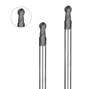
Optimizing Graphite Machining Speed and Feed: How Does RPM Affect Machining Quality?
In our field operations, we frequently encounter shops where identical machine setups yield wildly different surface finishes and tool life. For instance, one mold maker boosted table feed rates to push output, only to experience rapid end mill wear and micro-chipping along electrode edges. Our log analysis showed the issue was not the feed rate alone, but an unbalanced ratio between spindle speed, feed, and cutting load.
Successful production is never about blindly maxing out speeds or feed rates; it requires establishing a stable cutting rhythm. Optimal parameters must account for tool diameter, flute count, material grade, and the specific operation. Rebalancing your graphite end mill parameters stabilizes cutting forces, suppresses abnormal wear, and delivers predictable, high-precision results.
Why Excessively Low RPM Increases Graphite End Mill Wear
We frequently observe that intentionally lowering spindle speeds to “protect” a tool actually shortens its service life. One shop running deep cavity electrodes dropped their RPM, only to find their cutters wearing out twice as fast. On-site diagnostics revealed that the low speed caused unstable cutting action, forcing the tool edge to rub against abrasive grains rather than shearing them cleanly.
When spindle speed is insufficient, the tool fails to maintain a continuous shear, converting excess energy into friction and vibration. When evaluating premature wear, we look beyond coating quality to analyze the synergy between speed, feed, and depth of cut. Increasing your graphite end mill RPM—paired with a matched feed rate—substantially improves edge load conditions.
How Excessively High RPM Leads to Graphite Dust and Edge Chipping
Pushing spindle speeds to absolute machine limits to slash cycle times often backfires during precision finishing. While material removal increases, running at extreme RPM generates massive volumes of abrasive graphite dust and causes severe micro-chipping along delicate electrode borders.
Running a graphite end mill at excessively high speeds multiplies impact frequency at the cutting zone. Without optimizing tool geometry, chip evacuation, and feed rates simultaneously, corner breakout is guaranteed on thin-walled features. We always recommend making incremental speed adjustments based on real-time cutting feedback rather than running at maximum rated spindle limits.
How Does an Optimal RPM Improve Graphite Surface Finish?
During electrode finishing passes, maintaining process stability is far more important than maximizing chip volume. We once assisted a client struggling with persistent tool marks on high-precision molds despite using premium cutters. Fine-tuning their graphite machining RPM while recalibrating table feed instantly smoothed out the cutting action and eliminated surface defects.
Finding the correct spindle speed ensures uniform chip formation while eliminating harmonic chatter and tool deflections. Achieving mirror-like finishes on intricate molds requires evaluating speed settings alongside cutter geometry, tool paths, and vacuum evacuation. Running small parameter tests on test blocks is the fastest way to lock in the perfect surface finish window.

Optimizing RPM for Diamond Coated Graphite End Mills: How to Extend Tool Life?
In our extensive field work, we often see clients increase spindle speeds to boost output, only to experience severe tool wear fluctuations. One client used uncoated carbide cutters for high-speed electrode production; while initial cutting was fast, rapid edge wear required frequent tool offsets after just a few hours. We stabilized their production by pairing the right tool coating with a recalibrated speed-to-load ratio.
Simply cranking up rotational speed will not extend tool life; success depends on whether your cutter can handle the thermal and abrasive stresses of high-speed passes. Because graphite dust acts like fine sandpaper, pairing optimized RPM settings with a diamond coated graphite end mill significantly reduces abrasive wear, keeping dimensions stable during long production runs.
How Does Diamond Coating Enhance High-Speed Graphite Machining?
Our machining tests prove that fine graphite dust rapidly erodes unprotected carbide cutting edges during continuous production. Diamond coatings provide extreme hardness and a ultra-low friction coefficient, shielding the substrate from abrasive wear. This exceptional wear resistance makes diamond tooling the gold standard for high-speed, high-volume electrode production.
However, a diamond coating alone cannot guarantee superior part quality. Running coated tools with mismatched spindle speeds, feed rates, or tool paths still causes premature chipping. We always tailor high-speed parameters to cutter diameter and cavity depth, ensuring your diamond coated graphite end mill delivers maximum tool life.
RPM Differences: Diamond Coated Graphite End Mills vs Standard Carbide Tools
We frequently run side-by-side tests comparing tool performance on identical graphite grades. Standard carbide tools lose their sharp edge quickly, forcing operators to lower speeds to avoid edge breakdown. In contrast, diamond-coated cutters maintain clean cutting geometry at significantly higher surface speeds without degrading part accuracy.
Higher wear resistance does not mean you can ignore tool dynamics. When using micro-diameter tools for fine features, vibration control and chatter suppression remain top priorities. For large-diameter roughing cutters, the focus shifts to balancing stock removal with spindle load. Optimizing your graphite end mill RPM ensures you fully leverage the coating’s capabilities.
How Do You Select a Professional Supplier of Diamond Coated Graphite End Mills?
When helping clients source tooling, we notice buyers often focus solely on coating thickness while ignoring substrate quality and edge preparation. Sub-micron carbide substrates, micro-geometry, and coating adhesion vary wildly between manufacturers. Selecting a reputable diamond coated graphite end mill supplier directly impacts your machining consistency and cost per part.
We evaluate suppliers based on their practical application knowledge and technical support capabilities. A reliable partner recommends precise cutting parameters for your specific machine rigidity and graphite grade, helping you continuously optimize tool life and lower production costs over time.
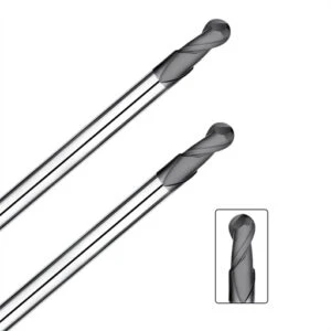
Graphite End Mill Wear Analysis: What Machining Issues Arise from Incorrect RPM Settings?
In our long-term field diagnostics, abnormal end mill wear is usually the first red flag reported by clients. We once audited a shop experiencing severe tool life fluctuations while machining identical graphite electrodes. Some tools lasted for hours, while others suffered rapid edge wear that compromised part tolerances. On-site log analysis confirmed that inconsistent spindle speed was the primary driver of premature failure.
Shops often blame inconsistent tool life strictly on carbide quality or graphite hardness. However, our engineering experience proves that the balance between spindle speed, feed rate, depth of cut, and tool geometry is just as critical. Running mismatched parameters causes rapid performance degradation, even when using premium tooling. We always audit the entire cutting system rather than assuming the tool itself is defective.
The Relationship Between Graphite End Mill Wear and RPM
Our machining tests confirm that RPM variations directly dictate the forces acting on the tool’s cutting edge. A mismatch between spindle speed and chip load prevents a smooth shear, causing heavy cutting force fluctuations. For example, operators who drop their RPM in deep cavities to “lighten the load” often experience increased friction, chatter, and accelerated wear on the graphite end mill.
Maintaining a stable cutting action is far more vital than simply pushing or pulling spindle speeds. When adjusting parameters, we evaluate tool diameter, flute geometry, stick-out length, and toolpath strategy. If we notice concentrated tip wear or uneven flaking, we immediately verify the speed-to-feed ratio before swapping out the tool.
How Can Graphite Edge Chipping Be Reduced Through RPM Optimization?
Corner breakout is a constant hurdle in precision graphite machining, particularly on thin-walled electrode features. We assisted a mold shop that boosted feed rates for cycle-time gains, only to suffer severe micro-chipping along sharp detail edges. Fine-tuning their spindle speed in relation to their table feed restored edge stability without sacrificing production output.
Edge chipping rarely stems from material brittleness alone; it usually results from excessive cutting impact and tool deflection. When RPM is too high, the rapid impact frequency causes micro-cracks along the cutting edge to propagate into full breakouts. Finding the optimal RPM window helps the tool transition smoothly in and out of complex contours.
Common RPM-Related Causes of Reduced Graphite Machining Quality
When troubleshooting surface finish defects, we frequently trace visible tool marks and dimensional errors back to improper spindle speeds. We have seen jobs where electrodes exhibited heavy chatter marks despite the cutter showing no visible damage. Further analysis showed that an unbalanced RPM-to-feed ratio was inducing harmonic vibration throughout the setup.
While tool sharpness, machine rigidity, and vacuum dust extraction all affect part quality, spindle speed remains the anchor parameter. Excessively low speeds increase rubbing friction, whereas excessively high speeds generate abrasive dust clouds and cause severe vibration. Locking in a stable RPM range before tuning feeds is the key to maintaining consistent graphite machining quality.
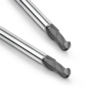
Best Practices for Optimizing Graphite End Mill RPM: Recommended CNC Machining Parameters
Most shop floor issues arise not from a lack of technical knowledge, but from uncertainty about how to adapt speed settings to specific cutting conditions. Because machine rigidity, spindle torque, material density, and part specs vary greatly, we avoid giving out single fixed parameters. Instead, we help operators establish a stable, repeatable parameter window through step-by-step testing.
Optimizing your graphite end mill speed starts with defining cutter diameter, operation type, and surface finish targets, then adjusting feed rate and depth of cut accordingly. High-speed electrode finishing demands maximum cutting stability, whereas large mold cavity milling requires balancing stock removal rates with tool longevity. Analyzing blueprints and cutting logs helps lock in the optimal machining strategy.
RPM Parameter Recommendations for EDM Graphite Electrode Machining
When consulting on EDM electrode projects, boosting cycle speed while holding tight tolerances is the number one challenge. Electrodes feature thin ribs, sharp corners, and deep cavities that place high demands on tool stability. Precision graphite electrode machining requires balancing spindle speed with table feed rather than pushing RPM in isolation.
Finishing passes demand smooth shearing action without heavy impacts. We determine appropriate graphite machining parameters by evaluating tool diameter, material density, and stock allowance. For micro-tools running intricate features, keeping cutting loads low protects fragile details, whereas roughing with larger cutters allows for higher material removal rates.
Insights on High-Speed RPM for Graphite Mold Machining
Milling large graphite mold cavities presents unique challenges, including extended run times, deep tool overhangs, and strict surface requirements. Operators often try to shorten cycle times by maxing out spindle speeds, only to accelerate tool wear and ruin surface finishes. Maintaining cutting stability throughout long passes is the real secret to successful high-speed milling.
When machining large molds, closely monitor spindle load, tool deflection, and vacuum dust extraction efficiency. High-speed settings must match your machine’s dynamic capabilities and cutter geometry. For long-duration runs, we establish a conservative baseline first before incrementally increasing speed to ensure predictable graphite end mill life.
Adjusting RPM Based on Graphite Material Grades
Machining performance varies dramatically across different graphite grades. Fine-grain graphite, high-density grades, and standard electrode materials differ significantly in hardness, grain structure, and abrasiveness. Simply copying parameters from one grade to another rarely delivers optimal surface quality or tool life.
We always re-evaluate spindle speeds when switching material suppliers or density grades. Harder, high-density graphite requires controlled speeds and stable chip loads to reduce tool wear, while softer grades require precise feed settings to prevent corner blowouts. Adjusting your graphite end mill RPM to match material properties ensures maximum process stability.
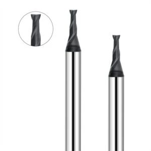
FAQ: Graphite End Mill RPM
In our field operations, spindle speed is the single most common variable operators ask about. While many search for a universal speed formula, practical experience shows that no single RPM applies to every job. Tool diameter, graphite density, spindle rigidity, operation type, and surface finish targets all dictate parameter selection.
Optimizing your cutting parameters requires defining your production goals first, then adjusting speed incrementally based on actual cutting feedback. Roughing passes prioritize stock removal efficiency, while finishing passes demand dimensional stability and edge retention. Always adjust your graphite end mill RPM based on live cutting conditions rather than copying parameters from older jobs.
What Is the Recommended RPM for Graphite Machining?
We frequently get asked for a broad RPM recommendation for electrode milling. In practice, target speeds depend directly on cutter diameter and application requirements. Micro-cutters require higher spindle speeds to maintain sufficient surface footage, whereas larger tools demand lower speeds to keep cutting forces and spindle loads within safe limits.
To establish the right baseline, identify your tool diameter, flute count, and graphite material grade, then pair your speed with a matching table feed. For high-precision graphite electrode machining, we always determine final parameters through live test passes—evaluating surface finish, corner sharpness, and edge wear.
What Speed Should I Run a Graphite End Mill?
When helping shops debug tool failures, we often find that machining issues stem from misunderstanding the relationship between spindle speed and chip load. Your graphite end mill speed controls not only stock removal rates, but also cutting stability, dust extraction efficiency, and overall tool longevity.
When proving out a new cutter, start with conservative parameters and gradually increase speed based on chip load and surface quality. If you observe excessive chatter, poor surface finish, or rapid edge breakdown, immediately rebalance your speed-to-feed ratio. Deep cavities, thin ribs, and micro-tools require extra caution during parameter tuning.
How Does RPM Affect Graphite End Mill Tool Life?
Spindle speed directly impacts cutter lifespan and tool replacement costs. We once audited a client who increased RPM to boost output, but because they left their feed rate unchanged, the cutting edge suffered severe abrasive wear within hours. Recalibrating their speed-to-feed ratio restored both tool life and dimensional accuracy.
If your tools suffer from unpredictable wear, check whether your graphite end mill RPM is too low—causing heavy rubbing friction—or too high—inducing destructive harmonic impacts. Setting an optimal speed protects fragile carbide edges, reduces micro-chipping, and prevents costly part scrap.
Can Diamond Coated Graphite End Mills Run at Higher RPM?
In high-speed milling environments, operators often ask if diamond coatings allow for unlimited spindle speeds. Compared to standard carbide tooling, diamond coated graphite end mills offer superior wear resistance and maintain a sharp, stable cutting edge much longer in abrasive materials.
However, a diamond coating does not mean you can ignore mechanical limits. Safe operating speeds still depend on tool diameter, machine rigidity, toolholder runout, and cavity depth. Increasing speed incrementally while monitoring wear patterns and dimensional stability is the best approach for high-speed graphite machining.






