


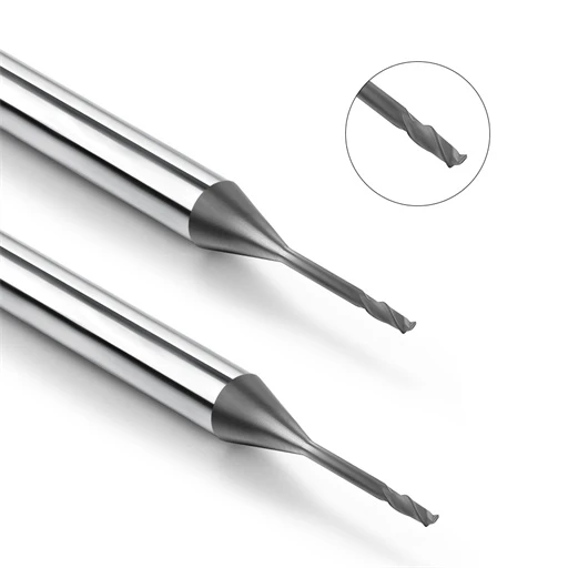
While optimizing a graphite electrode process for a European mold maker, we encountered a common pitfall: using a single graphite end mill at a fixed depth of cut across varying cavity depths. Initial cuts were smooth, but deeper passes caused subtle edge chipping. This micro-chipping degraded the surface finish, making the finished electrodes fail strict EDM tolerance limits.
Our on-site analysis revealed that the issue was not the tool coating or grade, but rigid cutting parameters. The client failed to adjust their settings based on cavity depth, tool geometry, and material structure. Because graphite is highly abrasive and brittle, setting the right depth of cut for graphite end mills directly controls cutting load, dust evacuation, and overall tool life.
Many CNC engineers pick the right diamond-coated tool but overlook proper graphite milling parameters. In high-speed machining, an aggressive axial load creates excessive edge pressure, while a conservative cut leads to poor efficiency and higher shop costs. Finding the right balance requires matching your cutting depth to your specific machine setup.
A reliable depth of cut for graphite end mills is never a static number. It demands a holistic evaluation of graphite grain size, tool overhang, axial versus radial cut ratios, and machine rigidity. For instance, deep-cavity work requires adjusting step-down passes to maximize long-neck tool stability while mitigating harmful harmonics.
During the finishing stage, optimizing your depth of cut for graphite end mills is critical to achieving superior surface finishes and extending tool life. Within a complete CNC graphite machining process, depth of cut bridges tool selection with productivity. Establishing structured cutting profiles ensures process stability and consistent electrode quality.
Have improper depth-of-cut settings ever caused unexpected tool wear or poor surface finishes in your shop, even with high-end tools? Let’s break down the exact formulas and parameters to solve this issue.
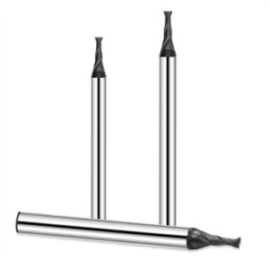
Graphite Cutting Depth Analysis: Why Does Cutting Depth Affect Machining Stability?
In CNC graphite machining, setup failures rarely stem from poor tool quality alone. Most issues trace back to mismatched graphite milling parameters, with cutting depth being the most frequent culprit. Varying the depth of cut for graphite end mills on identical workpieces directly alters system harmonics, chip loading, and dust extraction efficiency.
Because graphite is brittle and micro-abrasive, controlling your graphite cutting depth requires evaluating grain size, spindle condition, and tool geometry together. Rather than pursuing raw material removal rates, prioritizing cutting stability protects critical electrode tolerances and prevents premature edge breakdown.
How Do Cutting Depths Affect Cutting Forces and Machining Conditions?
Optimizing the graphite milling process requires balancing axial depth of cut (Ap) and radial depth of cut (Ae). Increasing your depth of cut per pass expands the engagement arc, escalating mechanical load. Without adequate tool holding or machine rigidity, this extra force instantly triggers high-frequency vibration and micro-chipping along brittle edges.
When machining delicate mold cavities, ramping up pass depth to cut cycle time often backfires into rapid tool wear. Decreasing the single-pass load and realigning feeds stabilizes tool force distribution. In high-precision applications, a refined depth of cut for graphite end mills delivers superior dimensional accuracy over aggressive passes.
Matching Cutting Depth to Graphite End Mill Diameter
Setting appropriate graphite milling parameters depends on the cutter diameter, flute length ratio, and cavity profile. Small-diameter tools lack structural rigidity to withstand high lateral forces. Applying heavy radial cuts to micro-tools inevitably causes tool deflection, poor surface finish, or outright tool breakage.
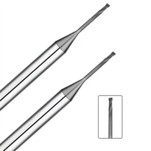
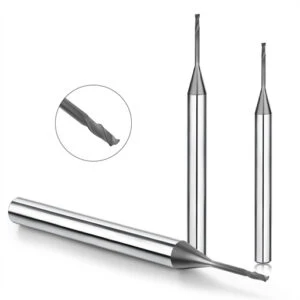
When milling narrow slots or intricate electrodes, engineers should employ a step-down approach using small-diameter diamond tools. Utilizing long-neck graphite end mills with reduced radial engagement lowers bending moments during deep-reach passes. This strategy mitigates tool deflection while extending tool life in tight tolerances.
Why Does an Excessive Graphite Cutting Depth Lead to Tool Chipping and Irregularities?
Overly aggressive cutting depths trigger severe mechanical stress during entry and exit passes. High impact forces easily break delicate graphite ribs, sharp corners, and thin walls. Furthermore, heavy passes generate dense graphite dust that clogs flutes, increasing localized friction and accelerating abrasive flaking on the diamond coating.
In high-speed operations, forcing deeper cuts to reduce cycle times often leads to frequent tool changes and costly rework. Maintaining control over your depth of cut for graphite end mills prevents micro-chipping and maintains clean chip evacuation. Balanced parameters ultimately yield predictable process reliability and optimal surface integrity.
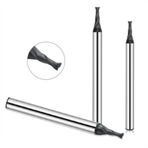
Optimizing Graphite Milling Parameters: How Does Depth of Cut Affect Machining Parameters?
Machining issues rarely happen because of one bad parameter; they stem from poor coordination across your entire process. Increasing your cut depth without balancing spindle speed, feed rate, or toolpath style accelerates wear and causes dimensional drift. Effective setup strategy demands treating your depth of cut for graphite end mills as an interconnected variable rather than an isolated choice.
Establishing reliable graphite milling parameters requires evaluating material grade, tool overhang, machine rigidity, and your target surface finish. Maintaining balanced loads across the cutter reduces vibration and maintains high chip clearance. For intricate mold cavities or thin-walled electrodes, parameter balance matters far more than pushing maximum cutting speeds.
How to Select Axial Depth and Radial Depth for Graphite Milling?
Selecting your axial depth (Ap) and radial depth (Ae or stepover) depends heavily on the machining phase. Roughing passes prioritize material removal rates by increasing tool engagement and distribution. Conversely, finishing passes demand a reduced depth of cut for graphite end mills to minimize tool deflection, prevent micro-chatter, and protect final part tolerances.
When machining large graphite blocks, using a higher axial engagement with a controlled radial stepover maximizes cutting efficiency. For narrow slots or deep cavities, reducing the depth per pass protects slender tools from lateral stress. Finding the right axial and radial balance requires adjusting settings to match real-time cutting conditions.
How Do Graphite Machining Conditions Affect Depth of Cut Settings?
Identical cut depth settings can yield vastly different results on different machine setups. Machine tool rigidity, spindle runout, vacuum suction pressure, and graphite grain size all impact cutting dynamics. Your operating environment directly dictates how aggressively you can set your graphite milling parameters without risking premature edge failure.
In deep-cavity applications, using standard cutting depth settings with long-reach tools frequently causes chatter and edge chipping. Reducing radial engagement while refining the toolpath stabilizes the cut and reduces tool load. Matching your cutting parameters to machine capabilities ensures process repeatability across complex CNC graphite machining runs.
How Can High-Speed Graphite Milling Be Optimized Through Spindle Speed, Feed Rate, and Depth of Cut?
High-speed graphite milling is not simply about maxing out spindle RPM; it requires synchronizing speed, feed rate, and cut depth. Running high RPM without matching chip load per tooth creates excessive friction, which quickly degrades diamond coatings. Maintaining continuous chip clearance keeps heat generation low and prevents abrasive wear along the flutes.
For example, increasing RPM without adjusting feed rates significantly shortens tool life. Rebalancing parameters by slightly lowering single-pass loads and aligning feed rates with higher spindle speeds restores tool longevity while improving efficiency. Sustainable high-speed machining relies on harmonizing your depth of cut for graphite end mills with overall machine dynamics.
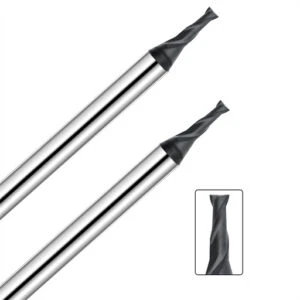
Selecting Graphite End Mills: How Tool Geometry Affects Optimal Cutting Depth
Switching cutter geometry under identical machine parameters often yields drastically different surface finishes and tool wear. The proper depth of cut for graphite end mills depends heavily on tool stiffness, core strength, and flute design. Matching parameter selection directly to cutter geometry remains essential for maintaining dimensional control and process efficiency.
In CNC graphite machining, choosing the right cutter involves evaluating feature accessibility, overhang length, and chip clearance capacity. Tool geometry dictates how cutting forces transfer through the spindle and workpiece interface. Utilizing a tailored cutting depth strategy for each specific cutter type prevents chatter while optimizing cycle times.
Differences in Cutting Depth Selection: Standard vs. Long-Neck Graphite End Mills
Standard-length end mills feature short flute lengths that deliver maximum radial rigidity and resistance to bending moments. When machining shallow cavities or open surfaces, engineers can apply aggressive step-downs to maximize material removal rates. Their structural stiffness permits setting a deeper depth of cut for graphite end mills without inducing harmful vibration.
Deep-cavity milling, however, requires long neck graphite end mills to reach recessed features without holder interference. Because extended tool overhang reduces structural stiffness, operators must decrease axial pass depth and radial stepover. Lowering single-pass loads minimizes bending deflection, ensuring clean sidewalls and preventing premature edge failure.
Minimizing Vibration and Tool Breakage Risks When Machining Deep Cavities with Long Neck Graphite End Mills
Deep-cavity electrode machining using improper long-reach tools frequently results in heavy chatter marks and micro-chipped corners. Standard long flutes suffer from excessive tool deflection, which generates high-frequency harmonics during heavy passes. Switching to reinforced long neck graphite end mills while reducing step-down depth stabilizes force distribution across the cutting zone.
Controlling parameter strategy matters far more than simply selecting a long tool. Engineers should evaluate the tool overhang-to-diameter ratio, reducing radial engagement as reach increases. Maintaining a lighter depth of cut for graphite end mills in deep cavities suppresses lateral deflection, extending tool life and preserving tight tolerance requirements.
How Do Diamond Coated Graphite End Mills Facilitate More Efficient Graphite Machining?
Abrasive graphite dust causes rapid micro-flaking on uncoated carbide edges during extended machining cycles. Premium diamond coated graphite end mills utilize chemical vapor deposition (CVD) to provide superior surface hardness, significantly resisting abrasive wear. This protective layer allows tools to hold sharp cutting geometries through long finishing passes.
However, advanced diamond coatings cannot compensate for mismatched cutting parameters. Excessive axial loads or heavy impacts will still fracture diamond layers and trigger micro-chipping along the edge. Adjusting your depth of cut for graphite end mills to match coating properties ensures predictable tool wear and optimizes overall shop productivity.
Graphite End Mill Tool Life Analysis: How Does Cutting Depth Affect Tool Longevity?
Managing tool consumption in electrode fabrication directly dictates operating costs and shop profitability. Tools with identical specifications often demonstrate vastly different wear rates depending on cutting parameters. Improper axial engagement remains a primary driver of unpredictable tool breakdown across CNC graphite machining environments.
Extending cutter longevity requires balancing mechanical loads with target removal rates rather than simply dialing back feeds. Setting an optimal depth of cut for graphite end mills stabilizes cutting pressure, reducing localized stress concentration. Controlled force distribution minimizes unexpected edge failure, making overall tool life predictable across production runs.
How Does Excessive Graphite Cutting Depth Accelerate Tool Wear?
Pushing aggressive depth per pass to shorten cycle times subjects cutting edges to high impact forces. This excessive load causes severe micro-flaking when milling sharp corners, thin ribs, or high-density, fine-grain graphite grades. Heavy engagement accelerates coating breakdown, leading to rapid tool wear and premature failure.
Exceeding system rigidity limits with heavy axial passes also prevents efficient dust removal from deep cuts. Trapped abrasive dust increases friction and temperature within the flutes. Engineers should adjust their graphite cutting depth to match cutter diameter and reach, avoiding aggressive passes that degrade tool integrity.
How Does an Appropriate Depth of Cut Reduce Graphite End Mill Edge Chipping?
Brittle graphite requires steady tool engagement to prevent sudden impact shocks along the cutting edge. Uncontrolled axial loads generate force spikes during corner entries, causing micro-fractures that escalate into severe tool damage. Mitigating impact energy through refined step-downs directly eliminates premature edge breakdown.
When finishing high-precision mold electrodes, combining a lighter axial engagement with consistent feed rates optimizes cutting dynamics. Controlled pass depths maintain uniform chip loads, effectively preventing graphite end mill edge chipping. This approach ensures dimensional accuracy while preserving high surface integrity across complex workpiece profiles.
How Can Graphite End Mill Tool Life Be Extended by Optimizing Graphite Milling Parameters?
Maximizing cutter longevity relies on orchestrating your entire parameter suite rather than tweaking a single variable. Sustainable graphite end mill tool life demands synchronizing spindle speed, feed rate, axial engagement, and radial stepover. These variables collectively govern thermal generation and mechanical wear rates at the cutting edge.
In high-speed operations, lowering single-pass loads while optimizing toolpaths stabilizes cutter forces without sacrificing throughput. Rebalancing your graphite milling parameters restores predictable wear progression and extends tool longevity. Aligning parameter strategy with machine capabilities ensures reliable production across all graphite machining runs.

Optimizing Graphite Surface Finish: How Does Depth of Cut Affect Machining Quality?
Achieving tight dimensional tolerances does not guarantee acceptable surface roughness (Ra). Shops often struggle with inconsistent textures, visible tool marks, or localized grain pullout during extended machining runs. These visual and structural defects directly stem from high cutting forces caused by improper depth of cut for graphite end mills during finishing passes.
Maintaining high graphite machining quality requires controlling tool deflection and material removal dynamics. Setting a lighter pass depth during finishing passes stabilizes cutting loads, preventing brittle edge fracture along intricate features. Balancing feed rate, axial step-down, and tool wear ensures pristine surface integrity across delicate mold electrodes.
Why Does an Improper Depth of Cut Lead to Surface Roughness?
Excessive depth per pass exerts heavy cutting pressure on brittle graphite, triggering micro-fracturing instead of clean shearing. Rather than producing a smooth surface, high impact loads cause grain pullout and localized pitting along sharp corners. This phenomenon frequently degrades high-precision electrodes where clean edge definition is critical.
Aggressive depth settings aimed at cutting cycle times frequently backfire into poor surface finishes and costly manual polishing. Decreasing single-pass engagement and refining the toolpath eliminates heavy chatter and tool chatter marks. Lowering chip load per tooth delivers superior graphite surface finish results while maintaining dimensional accuracy.
How Can Optimizing Depth of Cut Improve Graphite Surface Finish?
Delivering excellent surface finish requires adjusting your parameters across each machining phase. While roughing passes prioritize material removal, semi-finishing and finishing stages require a reduced depth of cut for graphite end mills. Progressive step-down reductions minimize cutting forces, preventing micro-chipping as the part reaches final size.
When machining precision electrodes, aligning pass depths with remaining finish allowances suppresses harmful tool harmonics. Furthermore, monitoring tool wear remains vital, as worn diamond coatings degrade surface quality regardless of parameter settings. Continuously fine-tuning parameters ensures consistent graphite machining quality across repetitive production cycles.
What Kind of Depth-of-Cut Control Is Required for High-Precision Graphite Machining Quality?
High-precision electrode production prioritizes overall process stability over raw cutting speed. Establishing optimal axial depths requires evaluating graphite grain size, cutter overhang, spindle runout, and final tolerance specs. Utilizing a refined, multi-pass step-down strategy prevents cumulative machining error and dimensional drift.
Consistently high-quality parts result from combining precise tool selection, optimized toolpaths, and controlled parameter execution. Maintaining tight control over your depth of cut for graphite end mills prevents surface pitting and protects critical rib geometry. Establishing standardized cutting profiles ensures reliable, repeatable precision in demanding shop environments.
Graphite Machining System Optimization: Establishing a Stable Machining Parameter Framework
Adjusting a single parameter rarely provides a permanent solution for CNC graphite machining issues. Increasing spindle RPM without balancing tool geometry, machine rigidity, and step-down engagement often causes heavy vibration and rapid tool failure. Achieving a truly reliable manufacturing process requires optimizing tools, machine hardware, parameters, and toolpaths as a unified graphite machining system.
A robust parameter framework adapts continuously to graphite grades, workpiece geometries, and production targets. Engineers must evaluate cutter overhang, spindle runout, vacuum dust evacuation, and step-down passes simultaneously. Prioritizing system stability over isolated parameter tweaks protects part accuracy while maintaining consistent production output.
How Are Tools, Machine Tools, and Parameters Optimized in Synergy?
Machining success depends on matching tool selection directly with machine tool capabilities and process parameters. A cutter’s maximum load limit changes drastically depending on machine enclosure rigidity, spindle dynamics, and workholding stability. Evaluating tool performance within your specific shop environment prevents premature tool failure and unexpected dimensional errors.
Systematic optimization requires auditing cutter geometry, spindle runout, and CAM toolpath strategies together. When milling fine features with micro-tools, reducing single-pass loads prevents deflection and maintains cutting stability. Coordinating these operational variables minimizes process variance across high-precision electrode runs.
How Do We Establish Graphite Milling Conditions Tailored to Different Materials?
Graphite material grades vary significantly in grain size, bulk density, and abrasiveness, ruling out a universal parameter formula. Fine-grained, high-density graphite demands strict control over cutting pressure to prevent edge breakout and severe coating wear. Conversely, standard electrode grades allow more aggressive depth settings to maximize material removal rates.
Establishing optimal graphite milling parameters involves structured testing to monitor tool wear, spindle sound, and surface roughness. Starting with conservative step-down passes allows operators to observe chip evacuation and tool edge stability before increasing feed rates. This methodical approach reduces scrap costs and establishes reliable baseline parameters.
How Do You Balance Efficiency and Machining Stability in High-Speed Graphite Milling?
High-speed graphite milling involves much more than simply maxing out spindle speed to reduce cycle times. Pushing high RPM without synchronizing feed rates and axial engagement causes thermal friction and inconsistent edge wear. Achieving peak efficiency requires balancing cutting loads with overall machine tool responsiveness.
Real productivity comes from harmonizing spindle RPM, feed rate, and your depth of cut for graphite end mills. When machining large production lots, maintaining long-term tool life takes priority over pushing maximum feed speeds on a single pass. A balanced cutting strategy delivers predictable process reliability while maintaining tight tolerance specs.
Recommended Graphite Cutting Depth Strategies for Different Machining Stages
A single cutting depth strategy should never be applied across an entire machining program. Common shop floor issues—such as premature tool wear, poor surface finish, and low output—usually stem from failing to separate roughing, semi-finishing, and finishing passes. Each phase serves a unique purpose and requires specific mechanical loads, stock removal rates, and surface requirements.
Tailoring your graphite cutting depth to each machining stage stabilizes overall process dynamics. Roughing prioritizes reliable material removal, semi-finishing balances accuracy with speed, and finishing focuses on tight dimensional control. Dividing your program into distinct phases and adjusting step-downs based on tool diameter and material density ensures repeatable production success.
How to Set Graphite End Mill Cutting Depth for Roughing?
Roughing passes focus on maximizing material removal rates without overloading machine capabilities. Increasing your depth of cut for graphite end mills during roughing boosts throughput, provided machine rigidity, workholding stability, and vacuum dust extraction are adequate. Excessive axial engagement, however, triggers high-frequency chatter and accelerates edge flaking on diamond coatings.
Pushing excessive pass depths to cut roughing times often backfires, causing tool breakage that halts production. Rebalancing axial engagement, feed rate, and toolpath motion establishes smooth cutting dynamics during heavy stock removal. When clearing large volumes of graphite, monitoring cutting forces remains far more effective than forcing maximum pass depths.
How to Balance Efficiency and Surface Quality During Semi-Finishing?
Semi-finishing acts as the critical bridge between heavy stock removal and final sizing. During this phase, engineers reduce axial engagement incrementally to lower cutting forces and relieve built-up stress. Beyond clearing remaining roughing stock, semi-finishing establishes a uniform finish allowance and stable cutting conditions for the final finishing passes.
When machining complex cavities or thin electrode ribs, operators must monitor tool deflection, chatter marks, and stock uniformity. Refining step-down depths and toolpaths prevents high lateral pressure from distorting delicate wall geometry. Selecting optimal semi-finishing parameters reduces finishing allowances and ensures consistent overall graphite machining quality.
How Can Reducing the Depth of Cut During the Finishing Stage Improve Graphite Surface Finish?
Finishing passes demand tight control over dimensional tolerances and surface roughness (Ra). Reducing your depth of cut for graphite end mills ensures smooth, continuous shearing rather than brittle material fracturing. Even with premium diamond-coated cutters, aggressive finishing passes leave deep tool marks and cause surface pitting.
Achieving a superior graphite surface finish requires monitoring tool wear, finish allowance, and feed rates together. Combining light axial engagement with steady feeds minimizes surface defects without causing rubbing or work hardening. Establishing a reliable finishing routine delivers repeatable surface quality across extended electrode production runs.
FAQ: Graphite End Mill Depth of Cut
Optimizing step-down parameters generates continuous discussion among CNC programmers and shop engineers. After selecting a diamond tool, machinists naturally ask: “What exact pass depth should I set?” or “Can I maintain standard parameters in deep cavities?” In CNC graphite machining, your axial engagement directly governs cutting forces, chip evacuation, and component accuracy.
Finding the optimal depth of cut for graphite end mills involves balancing material grain size, cutter overhang, machine rigidity, and process requirements. Below are practical answers to the most common setup questions encountered on the shop floor.
What Is the Recommended Depth of Cut for Graphite Milling?
Providing a single universal depth setting is impractical due to varying graphite grades and machine setups. Recommended parameters depend on cutter diameter, length-to-diameter (L/D) ratios, and your specific machining phase. Finishing micro-electrodes requires light engagement, whereas roughing large blocks permits aggressive axial passes to maximize removal rates.
Determining the ideal graphite cutting depth requires evaluating cutter flutes and machine dynamics together. During heavy roughing, operators can increase axial depth to boost productivity. Conversely, finishing passes demand a shallower pass depth to eliminate tool deflection and maintain tight tolerances.
How Deep Can You Cut Graphite with an End Mill?
Maximum cutting depth is governed by tool rigidity, holder stability, and system vibration rather than total flute length alone. Extending tool reach increases deflection risks, even if the cutter physically reaches the bottom of a deep cavity. Unsupported overhang generates high-frequency chatter that degrades part geometry and tool edges.
When milling deep slots or narrow cavities with extended reach, controlling lateral loads is critical. Engineers prevent deflection by reducing radial engagement, optimizing step-down passes, and refining toolpaths. Maintaining balanced cutting forces ensures process reliability throughout deep-reach operations.
Does Cutting Depth Affect Graphite End Mill Tool Life?
Axial engagement directly impacts cutter longevity by altering stress concentration along the cutting edge. Setting an excessive graphite cutting depth subjects diamond coatings to intense mechanical shocks, triggering premature flaking, corner breakdown, or tool breakage. This wear pattern accelerates quickly during high-speed production runs.
Extending graphite end mill tool life requires synchronizing pass depth with feed rates and spindle speeds. Maintaining a uniform chip load minimizes force spikes at corner entries. Controlling mechanical stress preserves diamond coating integrity and delivers predictable cutter longevity.
Can Long Neck Graphite End Mills Handle Deeper Cuts?
Long neck graphite end mills provide essential clearance for deep-cavity work, but they cannot handle the heavy parameters used with standard tools. The extended shank design lowers structural stiffness, making the tool vulnerable to bending moments under heavy axial loads.
Engineers must adjust cutting parameters when applying long-neck tools to deep mold cavities. Reducing axial engagement and radial stepover suppresses lateral forces and mitigates tool chatter. For deep-cavity work, maintaining parameter control is far more effective than forcing heavy depth passes.






