


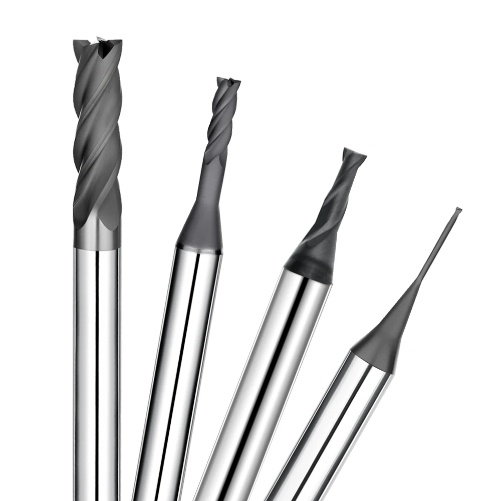
During a high-volume production run of precision EDM electrodes, we hit a familiar bottleneck on the shop floor. The tools cut smoothly during the first few hours, but as part count scaled, our tools developed subtle edge chipping. This micro-chipping ruined edge integrity and forced frequent tool changes.
EDM mold electrodes demand strict dimensional accuracy and zero edge breakdown. Even though we followed standard handbook speeds and used carbide tools, graphite end mill edge chipping kept interrupting our production line.
Our failure analysis showed that tool damage is rarely caused by a single variable. Graphite is highly abrasive and brittle, and its fine dust continuously wears down the sharp cutting edge. Unmatched speeds, incorrect tool geometry, and poor coating choices accelerate this failure.
To solve this, our engineering team re-evaluated the entire process. We focused on:
-
Graphite end mill geometry and edge strength design
-
Differences between 2-flute and 4-flute graphite end mills
-
Optimizing cutting speed, feed rate, and depth of cut (DOC)
-
Upgrading to premium diamond coated graphite end mills
Optimizing these factors eliminated early micro-chipping and dramatically improved tool life consistency. Many machine shops focus solely on spindle speed or tool cost, ignoring the fact that graphite cutting requires a fully integrated system.
This article shares practical strategies to minimize graphite end mill edge chipping and stabilize your processes. We break down tool wear mechanisms, geometry tweaks, parameter tuning, and system-level improvements.
If you struggle with short tool life or poor edge finish, ask yourself: Is the tool failing, or is your CNC graphite machining system out of sync?
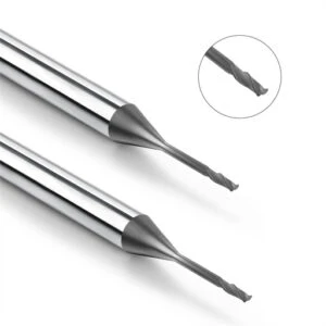
Analysis of Graphite End Mill Edge Chipping: Why Are Graphite End Mills Prone to Chipping?
In our graphite electrode machining projects, edge chipping on graphite end mills is a major issue affecting process stability. During one continuous production run for a mold manufacturer, the initial electrodes passed inspection, but tiny nicks soon appeared on the tool’s cutting edge. These nicks led to severe edge breakout on the electrodes, proving the issue was not bad tools, but poor alignment between material properties and machining conditions.
For many machinists, edge chipping seems to occur without warning during production. However, subtle warning signs almost always appear first, including changes in pitch sound, fine burrs on the workpiece, and microscopic tip wear. Rather than simply replacing broken cutters, our engineering team analyzes the material characteristics and cutting forces to eliminate the root cause of graphite end mill edge chipping.
How Do Graphite Material Properties Affect Edge Chipping?
Although graphite has low tensile strength, its brittle nature and layered crystalline structure make it prone to localized micro-fracturing. During high-speed milling or deep cavity roughing, continuous mechanical impacts create micro-cracks at the tool tip. These tiny cracks quickly propagate into full graphite end mill edge chipping.
Coarse-grain graphite structures and uneven machining allowances aggravate edge damage even when using standard parameters. To offset these material limitations, we evaluate density and grain size before setting edge strength and cutting strategies. Tailoring parameters to specific material grades prevents premature tool tip failure in CNC graphite machining.
The Relationship Between Graphite End Mill Wear and Micro-chipping
Tool wear in brittle materials rarely presents as gradual flank abrasion; it often begins as micro-chipping along the primary cutting edge. During delicate finishing passes, a cutter may maintain its target diameter while harbor microscopic defects caused by repetitive impacts. These subtle edge flaws degrade surface finish long before the tool completely breaks.
When investigating an unexpected drop in tool life, we found tools with nominal outer diameters but chipped cutting edges. The original feed rates generated high chip loads per tooth, overstressing the delicate edge. Assessing graphite end mill lifespan requires monitoring total edge integrity and surface quality, not just physical wear measurements.
How Do Graphite Dust and Cutting Impacts Accelerate Graphite End Mill Failure?
Inadequate dust evacuation accelerates tool degradation during high-volume production. Airborne graphite powder is highly abrasive; when fine dust lingers in the cutting zone, it increases abrasive friction against the flank face. This extra friction explains why identical tools yield vastly different lifespans on machines with varying vacuum capacities.
Intermittent cutting impacts also trigger sudden tool breakage during high-speed cornering or aggressive ramping moves. Unstable cutting loads generate sharp force spikes directly on the fragile cutter tip. Combining optimized tool geometry, strong dust removal, and smooth motion paths prevents premature graphite end mill edge chipping.
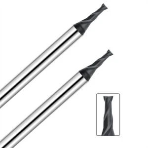
Graphite End Mill Wear Mechanisms: Key Factors Affecting Tool Life
Inconsistent tool performance remains a major pain point in production shops running graphite electrodes and mold components. Machinists often assume that upgrading to a harder carbide grade will automatically stop wear, but shop-floor reality is far more complex. Factors driving tool failure stem from material abrasiveness, edge preparation quality, dynamic cutting loads, and overall spindle stability.
During a long-run electrode job, a client experienced wide variations in cutter longevity despite using identical tools and workpiece materials. Our post-mortem showed the cutters were not failing from catastrophic breakage, but from insidious abrasive wear that raised cutting forces until edge collapse occurred. Controlling these wear mechanisms through strategic parameters is essential to extend graphite end mill lifespan.
How Does Abrasive Wear Reduce Tool Life in Graphite Machining?
Abrasive wear is the leading cause of premature tool failure when milling abrasive carbon materials. Fine carbon dust acts like liquid sandpaper, relentlessly rubbing against the tool’s rake and clearance faces to dull the sharp cutting edge. As edge dulling progresses, cutting forces surge, increasing the likelihood of catastrophic graphite end mill edge chipping.
Workpiece surface scratches, excessive dust buildup on flutes, and pitch shifts during cutting signal serious edge degradation. We monitor flank wear limits and surface finish rather than relying solely on total part count to dictate tool changes. Controlling the rate of micro-abrasion is critical for maintaining high precision in CNC graphite machining.
How Do Improper Graphite Machining Parameters Lead to Abnormal Tool Wear?
Premature tool failure is frequently caused by mismatched speed and feed setups rather than inherent tool defects. Pushing feed rates too high without considering tool diameter or machine rigidity severely overloads the cutting edge. This sudden rise in mechanical force triggers rapid flank wear and localized edge breakdown.
In a deep-cavity electrode project, aggressive feed rates initially saved cycle time but drastically shortened tool life in the deep-reach zones. We restored process stability by optimizing spindle speed, depth of cut, and chip load per tooth to reduce localized forces. Graphite machining marameter tuning must always reflect real-world machine limits rather than rigid reference charts.
How Does Cutting Edge Geometry Affect Graphite End Mill Durability?
Tool design directly determines how a cutter handles cutting forces and distributes thermal stress during milling. Rake angle, clearance angle, edge preparation, and flute geometry all impact tool strength. When cutting brittle graphite, an overly sharp, un-honed edge yields fast initial cuts but quickly micro-chips under sustained machining loads.
We match graphite end mill geometry directly to the target application. Precision electrode features require edge stability and micro-hones, while heavy roughing demands high core strength and maximum chip clearance. Tailoring tool geometry to your specific material hardness keeps edge performance stable far longer than simply buying harder carbide.
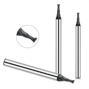
Optimizing Graphite End Mill Geometry: Tool Designs to Reduce Edge Chipping
When solving graphite electrode machining problems, tool failure often stems from a mismatch between cutter geometry and the operation. Precision electrode manufacturing demands tool designs that can handle continuous abrasive loads and complex cavity geometries without premature failure. Selecting the correct geometry directly improves cutting stability and edge toughness.
During a deep-cavity electrode project, a client experienced frequent micro-chipping at the tool tip using standard high-speed cutters. Our failure analysis revealed that the issue was caused by poor chip evacuation and insufficient edge support at depth. In brittle carbon milling, an ultra-sharp edge is rarely the answer; success requires balancing edge strength with efficient dust clearance.
Structural Differences Between 2-Flute and 4-Flute Graphite End Mills
Choosing between 2-flute and 4-flute designs depends heavily on your specific machining goals. A 2-flute graphite end mill features wider chip pockets, making it the top choice for deep slots and heavy pocketing where dust packing is a risk. Ample chip space prevents dust buildup, lowering cutting resistance and heat accumulation.
For finishing operations where surface quality and dimensional accuracy matter most, a 4-flute end mill excels. The additional flutes distribute the workload across more cutting points, producing a smoother finish. However, using 4 flutes in deep cavities can lead to dust packing if vacuum suction is inadequate, increasing the risk of sudden graphite end mill edge chipping.
How Do Flute Design and Helix Angle Affect Graphite Cutting Stability?
Flute geometry and helix angle govern how cutting forces transfer through the tool during high-speed milling. A well-designed flute profile clears abrasive dust quickly, while an optimized helix angle ensures smooth engagement with the workpiece. Proper force distribution minimizes impact spikes on the delicate cutting edge.
In high-speed operations, tweaking the helix angle and flute profile often eliminates chatter without changing feeds or speeds. Reducing vibration is especially crucial when machining thin-walled electrodes or fine ribs where tool flex occurs. We select specific helix configurations based on cut depth, feature rigidity, and target feed rates.
How Are Custom Graphite Milling Cutters Optimized for Complex Graphite Electrodes?
Standard off-the-shelf cutters often fail when machining intricate electrodes with complex contours or deep narrow ribs. On projects involving tight radii and deep cavities, standard tools frequently suffer from excessive deflection and short service life. Designing custom tool lengths and specialized necked shanks overcomes these physical reach limitations.
Custom graphite milling cutters optimize core thickness and clearance angles for demanding geometry, reducing tool chatter and edge breakout. While standard tools work well for general milling, custom solutions deliver the stability required for tight-tolerance molds. Are your current tooling failures caused by material hardness, or is your cutter geometry simply misaligned with the job?
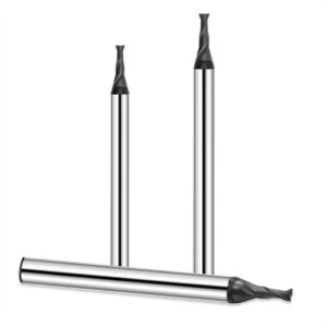
Optimizing Graphite Machining Parameters: Reducing the Risk of Chipping
In high-volume graphite electrode manufacturing, tool failure often stems from improper feeds and speeds rather than defective tooling. Machinists trying to boost productivity frequently increase spindle speeds and feed rates without considering carbon brittle fracture limits or edge strength. This approach leads to premature flank wear, surface micro-cracking, and unexpected edge breakdown.
On a precision mold project, aggressive roughing rates caused uneven cutting forces and sporadic tool failure across production runs. Instead of simply slowing down the machine, we rebalanced cutting speed, feed rate, radial engagement, and axial depth of cut. Optimizing parameters in CNC graphite machining is always about striking the perfect balance between material removal rate and consistent tool life.
How to Optimize Graphite Cutting Speed and Feed Rate?
Cutting speed and feed per tooth are the primary variables for establishing stable machining conditions. Setting the correct feed rate keeps chip load consistent, preventing sudden impact spikes on the tool tip. An overly high feed rate causes micro-cracks along the flute, while an excessively low feed rate causes the tool to rub, accelerating abrasive wear.
During a small-electrode project, a tool performed well in open cuts but chipped frequently when entering tight corners and narrow slots. We solved the issue by applying corner deceleration routines and optimizing toolpaths to maintain constant cutter engagement. Parameter selection must always account for graphite density, feature geometry, and machine tool rigidity.
Impact of Spindle Speed and Depth of Cut on Graphite End Mill Wear
Spindle speed and depth of cut directly govern thermal loads and deflection forces acting on the tool. Excessive spindle speeds increase abrasive friction along the flank face, while large cut depths generate high lateral forces that cause tool chatter. These mechanical stress spikes accelerate graphite end mill wear, especially when using long overhang setups in deep cavities.
When analyzing a batch of prematurely worn cutters, we found no major fracture sites, but severe, continuous flank wear along the margins. The root cause was excessive axial depth of cut, which subjected the cutter to heavy, continuous loading. In production, roughing passes should maximize chip evacuation, while finishing passes must reduce radial engagement to preserve edge integrity.
Adjusting Graphite Machining Parameters Based on Material Hardness
Graphite grades vary widely in grain size, shore hardness, and density, requiring distinct parameter setups. High-density, fine-grain graphite offers excellent detail retention but increases abrasive cutting resistance. Conversely, coarse-grain graphite cuts easily, but its low binder strength makes thin-walled features highly prone to edge breakout during heavy cuts.
We tailor speed and feed parameters directly to the specific graphite material grade and part geometry. For fine-grain graphite, we control tool load to slow down abrasive wear; for delicate electrode features, we prioritize low cutting forces to protect thin walls. Matching material characteristics with optimized speeds prevents unexpected graphite end mill edge chipping.
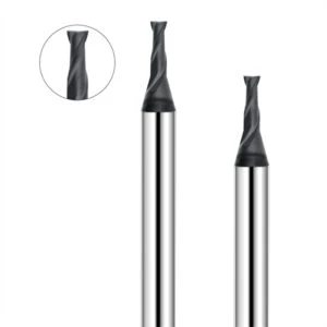
Diamond Coated Graphite End Mills: A Key Solution for Extending Tool Life
In precision graphite electrode machining, high-performance tool coatings are essential for maintaining stable dimensions over long production runs. Uncoated carbide tools experience rapid abrasive wear and micro-fatigue, leading to edge breakdown when cutting dense graphite grades. Upgrading to premium diamond coated graphite end mills provides the extreme surface hardness required to survive highly abrasive cutting environments.
A high-volume EDM mold client struggled with dimensional drift across batch runs, requiring constant offset corrections at the control panel. Tool analysis revealed that premature flank wear and loss of edge sharpess were causing the accuracy drop rather than tool breakage. Pairing optimized edge geometry with high-adhesion diamond coatings stabilized cutting forces and maintained tight tolerances across the entire production cycle.
Why Are Diamond Coated Graphite End Mills Ideal for High-Speed Graphite Machining?
Fine carbon dust generated during high-speed milling acts as a constant abrasive agent against the tool flank. Diamond-coated tools feature an ultra-hard carbon film with an extremely low coefficient of friction, protecting the cutting edge during high-RPM passes. This protective barrier preserves sharpness and resists edge degradation during rapid stock removal.
In high-speed finishing operations, short cycle times require elevated surface speeds that would instantly wear uncoated tools. Rapid edge dulling on standard tools causes dimensional drift between the first and last feature of a single workpiece. Combining proper spindle speeds and feeds with high-density diamond coatings ensures predictable tool wear during CNC graphite machining.
How Does Diamond Coating Improve the Wear Resistance of Graphite End Mills?
Diamond coatings do more than delay flank wear; they maintain structural edge stability under continuous machining stress. Synthetic CVD diamond layers shield the underlying carbide substrate from direct contact with abrasive graphite particles. This hard shell prevents micro-cracks from forming on the rake face, dramatically reducing graphite end mill edge chipping.
Comparative shop-floor testing shows that uncoated tools lose sharp cutting profiles quickly, whereas diamond-coated cutters retain true geometry much longer. However, coating quality alone cannot compensate for bad machining practices or incorrect substrate preparation. Substrate quality, edge honing, and parameter tuning must work in harmony to maximize total tool life.
How Do You Choose a Reliable Supplier of Diamond Coated Graphite End Mills?
Selecting a reliable diamond coated graphite end mill supplier requires looking beyond glossy catalog specifications to evaluate their real-world application engineering expertise. A knowledgeable vendor analyzes your specific graphite grade, machine rigidity, and vacuum capabilities before recommending a tool style. They provide tailored geometries rather than pushing generic, off-the-shelf cutters.
Shops frequently swap tool brands without solving underlying wear issues because they ignore process variables. Roughing deep cavities and high-speed rib finishing require vastly different substrate preparations, flute designs, and coating thicknesses. When evaluating diamond coated graphite end mills, prioritize vendors who offer verified field data and technical application support over those selling on low price alone.
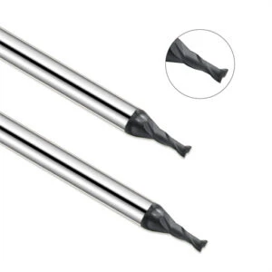
Optimizing the Graphite Machining System: Establishing a Stable Machining Solution
Through our extensive experience serving EDM electrode shops, we have found that inconsistent tool life is rarely caused by a single isolated variable. Machinists often switch cutter brands or tweak feed rates, yet issues like graphite end mill edge chipping, severe flank wear, and dimensional drift persist. Achieving long-term process stability requires system-level optimization across equipment conditions, tool selection, parameter tuning, and dust extraction.
During a continuous production project, a client focused purely on tool speeds and catalog specs while ignoring process alignment. Production data revealed that tool failures spiked in zones with poor vacuum airflow, erratic cutting loads, or excessive tool overhang. Re-aligning the complete system dramatically improved process consistency, proving that graphite cutting must be engineered as an integrated manufacturing system.
How Does a CNC Graphite Machining System Reduce Abnormal Tool Damage?
Analyzing failure logs proves that a well-calibrated CNC graphite machining system significantly lowers the risk of unexpected tool failure. Machine tool rigidity, spindle runout, fixture damping, and vacuum suction strength directly impact the forces acting on the tool tip. If any system component lags, even the highest-grade diamond-coated tool will fail prematurely under unstable loads.
During a deep-cavity electrode job, standard tools cut smoothly near the surface but suffered micro-chipping at depth. The failure was driven by chatter from tool overhang combined with heavy dust buildup inside the cavity. Shortening the tool extension, refining the toolpath, and boosting dust extraction velocity completely stabilized cutter performance.
Systemic Alignment of Tool Selection, Machining Parameters, and Dust Control
Achieving consistent results requires strict alignment between tool geometry, cutting parameters, and shop-floor dust collection. Machining delicate, narrow rib electrodes demands high edge stability and clean chip clearing, whereas heavy stock removal calls for maximum core stiffness. Mismatching tool design with the job application triggers rapid abrasive wear regardless of how well parameters are tuned.
Furthermore, airborne graphite dust management is vital for maintaining tool edge integrity. Abnormally short tool life almost always correlates with poor chip evacuation and heavy dust re-cutting. Installing high-velocity vacuum hoods, keeping the work environment clean, and tailoring radial engagement prevents abrasive powder from degrading the graphite end mill.
How Can a Graphite Machining System Extend Graphite End Mill Life?
Our primary goal when optimizing graphite operations is achieving predictable production consistency rather than pushing peak metal removal rates. Engineering a holistic process reduces peak mechanical loads, prevents chatter, and maximizes graphite end mill service life. This systematic control converts unpredictable tool wear into a repeatable, scheduled maintenance cycle.
Comparative shop testing demonstrates that aggressive high-speed setups cause frequent dimensional fluctuations and unexpected tool breakage. Conversely, a system-optimized approach delivers smooth cutting action, tight part tolerances, and predictable tool wear over thousands of parts. Is your shop fighting isolated tool defects, or is it time to upgrade your entire machining process?
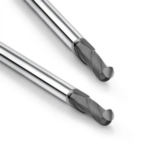
Guide to Choosing Custom Graphite Milling Cutters: Addressing Specialized Machining Needs
Standard off-the-shelf tooling often falls short when tackling complex electrode geometries, deep cavity molds, or tight-tolerance ribs. These challenging features demand specific cutter designs to handle extreme reach and severe abrasive wear without losing edge integrity. On a complex contoured electrode job, standard tools finished the cut but suffered chatter marks and inconsistent edge quality in narrow passages.
Increasing substrate hardness alone will not fix vibration or poor finish; the real solution lies in optimizing tool proportions and edge geometry. Selecting custom graphite milling cutters allows machinists to adjust flute length, shank necking, and core thickness for demanding jobs. Tailoring tool construction to specific cutting loads delivers superior stability and surface accuracy across specialized applications.
When Is a Custom Graphite Milling Cutter Necessary?
Custom tooling becomes essential when standard end mills cannot maintain dimensional stability or edge integrity. Machining deep narrow slots, complex mold radii, and delicate rib features often leads to tool deflection and poor chip evacuation when using standard tools. When standard options compromise quality, engineered cutter designs bridge the gap.
In a deep-cavity electrode project, long overhang setups caused tool chatter that ruined part accuracy. We resolved the issue by engineering custom cutters with optimized flute-to-neck ratios, larger core diameters, and improved dust clearance pockets. Custom tools should not be used for every job, but they provide massive returns when feature geometry exceeds standard tool limits.
How Do Long Neck Graphite End Mills Solve Deep-Cavity Machining Challenges?
Reaching deep cavities with standard cutters requires long tool extensions, which drastically reduces tool rigidity and induces chatter. Excessive stickout increases runout, accelerating wear and leading to sudden graphite end mill edge chipping. Purpose-built long-neck graphite end mills maintain structural stiffness while providing the clearance needed for deep pockets.
When milling deep EDM mold cavities, a long effective reach is mandatory. In early testing, standard long tools suffered from excessive flex, causing dimensional taper along deep walls. Upgrading to tapered-neck end mills with optimized core diameters eliminated deflection, allowing smooth, chatter-free cuts at depth. Success in deep cavities requires balancing reach against cutter stiffness.
How Do You Select the Right Graphite End Mill Geometry for Specific Machining Scenarios?
Tool selection must begin with a thorough analysis of part geometry and operation type rather than simply pulling a standard size from the crib. Roughing requires high chip evacuation and core strength, finishing demands fine edge hones and low friction, and micro-machining prioritizes tip stability. Each scenario calls for distinct flute counts and clearance angles.
We customize graphite end mill features—such as helix angles, rake angles, and edge preparations—to match the cutting load. Fine-detail rib electrodes require low cutting resistance to prevent edge breakout, while heavy block milling demands maximum dust clearance. Matching tool geometry directly to your shop’s operating environment turns troublesome jobs into repeatable, high-yield processes.
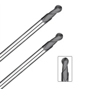
Extending Graphite End Mill Life through an Optimized Graphite Machining System
Years of milling high-precision graphite electrodes prove that premature tool wear, severe edge breakout, and unstable dimensions are rarely caused by a single isolated variable. Achieving consistent production requires aligning graphite material properties, end mill geometries, and cutting parameters into a synchronized workflow. Every variable across the setup directly impacts final edge integrity and overall tool life.
If your shop suffers from erratic cutter life or frequent edge micro-chipping, stop swapping tool brands and perform a complete process audit. Our engineering team troubleshoots by evaluating cutter design, speed/feed relationships, vacuum airflow, and spindle dynamics together. Implementing a well-balanced CNC graphite machining system maximizes tool performance, eliminates scrap, and delivers predictable shop-floor productivity.
A Comprehensive Solution: From Tool Design and Parameter Optimization to the Machining System
Long-term process stability requires harmony across your entire manufacturing line. Optimized cutter designs absorb mechanical shock, precise parameters prevent excessive chip loads, and stable machine setups with strong dust evacuation prevent abrasive re-cutting. Tuning a single variable yields minimal gains; true stability comes from addressing root causes across the entire machining process.
Evaluate your electrode milling line against three critical benchmarks: Is your cutter geometry engineered for the specific feature design? Are your speeds and feeds matched to the graphite grade’s binder strength? Does your vacuum system prevent dust buildup in deep cuts? Addressing these three factors resolves most cases of premature graphite end mill edge chipping.
Reducing Machining Costs by Selecting the Right Graphite End Mill
Reducing total machining costs is not about purchasing cheap cutters; it is about eliminating hidden downtime across production batches. Low-cost cutters with unpredictable wear rates drive up total manufacturing costs through frequent tool changes, part re-inspections, and costly scrap. Investing in high-performance diamond-coated graphite end mills lowers your total cost per part by ensuring continuous, unattended operation.
When producing high-precision mold components, monitor cutter performance under true operating conditions rather than relying on standard catalog charts. Track flank wear trends, edge integrity, and wall taper across sequential parts to establish reliable tool-change intervals. Tailoring tool selection to your material density and machine rigidity yields far better returns than relying on generic, off-the-shelf recommendations.
Achieving Stable Machining through Partnership with a Specialized Diamond Coated Graphite End Mill Supplier
A value-driven tooling partner offers deep application engineering knowledge, not just tool orders. Choosing the correct substrate, edge prep, and diamond coating requires expert insight, especially when running high-speed finishing or deep-cavity rib operations. Partnering with experienced technical specialists ensures your tooling strategy adapts to evolving project requirements.
To solve recurring tool life issues, compile your machining data—including graphite grade specs, cavity depths, spindle limits, and failure photos—and consult with a specialized graphite end mill supplier. Analyzing real-world cutting conditions quickly reveals whether failures stem from tool deflection, thermal shock, or abrasive wear.
Our application engineers regularly optimize tooling strategies using customer workpiece prints and machine specs to eliminate production bottlenecks. Before purchasing another batch of cutters, evaluate whether your machine parameters, dust collection, and tool geometries are truly aligned. Is your current tooling setup driving maximum productivity, or is it time to upgrade your graphite machining strategy?

FAQ: Graphite End Mill Edge Chipping
Machinists running graphite electrodes frequently hit the same wall: tools perform well initially, but premature edge damage, dimensional drift, and tool breakdown quickly follow. We compiled these answers from real shop-floor troubleshooting calls to help you diagnose and eliminate edge failures on your CNC line.
Process stability in carbon milling depends on much more than choosing a hard cutter substrate. It requires harmonizing graphite material properties, cutter geometry, speed and feed parameters, and dust vacuum capacity. Comparing your setup against these engineering FAQs will help pinpoint the root causes of short tool life.
Why Do Graphite End Mills Chip Easily During CNC Machining?
Cutters chip during carbon milling not because the material is hard to cut, but because carbon fractures brittly during shearing. Continuous mechanical impact from abrasive particles causes micro-cracking at the cutting tip. Mismatched edge geometry, weak edge hones, or excessive feeds quickly convert these micro-cracks into full graphite end mill edge chipping.
If you face recurring chipping, audit these three areas immediately: substrate-to-grade match, feed per tooth, and spindle vibration. On a recent troubleshooting job, a client tested five different tool brands without success. The root failure was severe chatter during deep pocketing, which repeatedly pounded the brittle tool edge until it failed.
How to Reduce Graphite End Mill Wear and Improve Tool Life?
Maximizing cutter longevity requires focusing on long-term process consistency rather than short-term metal removal rates. Extending tool life requires systematic adjustments across tool geometry, speeds, feeds, and dust extraction. Evaluating flank wear patterns helps verify whether your feeds and speeds match the cutter’s physical limits.
Adjusting spindle speeds and reducing radial step-over prevents thermal stress and abrasive edge breakdown. Shop testing proves that pairing optimized geometries with proper cutting parameters eliminates erratic wear and significantly extends graphite end mill lifespan.
Which Is Better: 2-Flute or 4-Flute Graphite End Mills?
Choosing between a 2-flute and 4-flute cutter depends entirely on feature geometry and chip clearance needs. Neither design is universally superior; each serves distinct machining objectives on the shop floor.
A 2-flute graphite end mill provides wider flutes for deep pocketing and ribbing, preventing abrasive dust packing. A 4-flute end mill offers higher core rigidity and extra cutting edges, making it ideal for high-precision finishing passes. Select flute counts based on cut depth, feature rigidity, and vacuum velocity rather than rule-of-thumb habits.
How Does Diamond Coating Improve Graphite Machining Performance?
In high-speed operations, friction between carbon particles and the tool flank drives rapid abrasive wear. Synthetic CVD diamond film acts as a super-hard barrier, drastically lowering friction and preventing premature edge dulling.
For high-density carbon grades or long batch runs, diamond-coated graphite end mills are mandatory for tight dimensional control. However, diamond coatings cannot offset incorrect edge preparation or weak vacuum extraction. Achieving maximum tool life requires aligning coating quality, cutter geometry, and parameter tuning in your CNC graphite machining system.






