


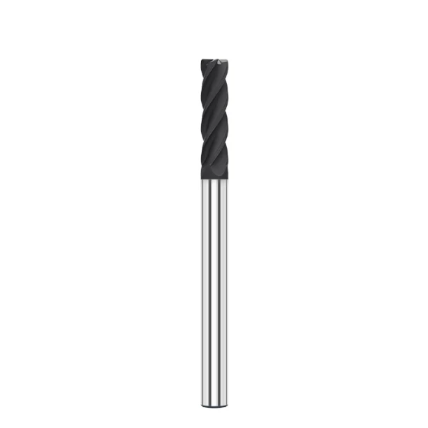
In precision mold making and electrode production, engineers often face a persistent issue. Graphite components meet strict dimensional tolerances after finishing, yet micro-burrs appear along the edges. These tiny edge burrs jeopardize subsequent electrical discharge machining (EDM) performance, assembly accuracy, and overall surface quality.
We recently assisted a precision mold client struggling with thin-wall graphite electrodes. While roughing went smoothly, irregular burrs constantly flared up on sharp corners during the final pass. The client initially blamed the raw material, but our on-site audit proved otherwise. The burrs resulted from an unoptimized mix of material properties, tool wear, cutting parameters, and machine stability.
In real-world CNC graphite machining, a burr is rarely just “uncut material.” It is a dynamic defect caused by particle fracturing, edge chipping, and unstable cutting forces. Without optimized graphite milling strategies, even premium tools will fail. Incorrect graphite milling parameters settings inevitably lead to edge chipping and poor surface integrity.
Preventing burrs requires evaluating the entire machining system, not just swapping end mills. Success depends on tool geometry, feed rates, toolpath motion, dust evacuation, and finishing allowances. For high-precision jobs, we recommend diamond coated end mills. Their exceptional hardness maintains sharp cutting edges, reduces tool wear, and eliminates machining defects.
This guide explores the root causes of graphite machining burr formation based on real shop-floor experience. You will learn how to build a robust CNC graphite machining quality control process through parameter tuning and proper tooling selection.
In graphite machining, the real challenge is not just making a single cut, but maintaining burr-free precision consistently across long production runs. Isn’t that the exact outcome every machining engineer strives to achieve?
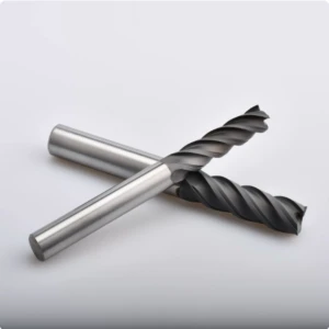
Graphite Machining Burr Analysis: Why Does CNC Graphite Machining Tend to Produce Burrs?
In precision electrode and mold production, a persistent graphite machining burr often frustrates experienced operators. Many shops assume that using ultra-hard tools and tight tolerances automatically prevents edge defects. However, real-world experience shows that burr formation involves a complex interaction of material grain, cutting parameters, and tool condition.
We recently audited a shop machining intricate graphite electrodes that suffered from severe edge spalling despite passing dimensional checks. The root cause was not tool life alone, but fluctuating cutting loads during finishing passes and rigid toolpaths. Eliminating burrs in CNC graphite machining requires optimizing the entire cutting ecosystem rather than simply shallowing the depth of cut.
Graphite Edge Burr Formation Mechanism: How Do Graphite Material Properties Affect Machining Burrs?
The micro-mechanics of graphite edge burr formation stem directly from inherent graphite material properties. Unlike metals that deform plastically under load, graphite is extremely brittle and fails through brittle fracture and grain boundary cracking. When cutting edges exit the material, uncontrolled stress concentration causes microscopic breakout instead of clean shear cuts.
Factors such as grain size, density, and micro-porosity heavily dictate edge integrity during high-speed milling. Excessive feed rates on thin-walled sections overwhelm the material’s local tensile strength, sparking severe edge chipping. Successful machining requires tailoring chip load and edge geometry to the specific graphite grade rather than applying standard metalworking logic.
Analysis of Graphite Machining Defects: The Relationship Between Burrs, Edge Chipping, and Surface Defects
On the shop floor, a Graphite Machining Burr rarely appears as an isolated quality issue. It typically coexists with other graphite machining defects, such as micro-chipping, excessive surface roughness, and localized material breakout. These flaws are interconnected, often triggered by subtle cutting force spikes as the cutting tool wears down.
For precision EDM electrodes, poor edge definition directly compromises discharge accuracy and mold cavity detail. When troubleshooting surface defects, engineers must look beyond the final cut and review the entire process chain. Burrs are usually a warning sign of system instability, whether caused by poor dust extraction, inadequate tool paths, or aggressive feeds.
How Does Graphite Material Brittleness Lead to Edge Chipping and Burrs?
Understanding graphite brittleness is essential for controlling edge chipping on fine details and sharp corners. Because synthetic graphite consists of bonded carbon grains, unstable cutting forces easily trigger micro-cracks along grain boundaries. This explains why standard geometries fail abruptly when transitioning into deep cavities or delicate thin walls.
We prevent these failures by using specialized end mills with tailored rake angles, higher spindle speeds, and refined finishing allowances. These adjustments distribute cutting forces evenly, reducing violent material breakout. Have you ever produced a graphite electrode that passed all coordinate measuring machine (CMM) checks, yet still failed visual inspection due to edge defects?
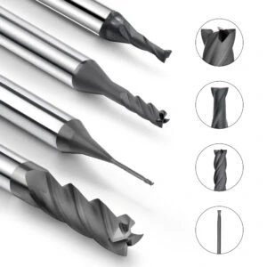
Enhancing Graphite Machining Quality: Key Factors Influencing Burrs
In precision graphite electrode and component production, edge defects rarely result from a single localized mistake. Even when shops select specialized tooling and enforce tight tolerances, micro-burrs and edge chipping still occur. Real-world engineering analysis proves that true graphite machining quality relies on aligning the entire process chain—from raw material selection to machine stability.
Improving quality is not simply about pushing faster feed rates; it requires stabilizing the cutting load while maintaining productivity. In high-tolerance applications like mold inserts, slight cutting force spikes can instantly compromise delicate edges. Therefore, we evaluate tool wear, toolpath motion, chip load, and dust management as an interconnected system rather than treating burrs as isolated defects.
How Do Burr Issues Affect Graphite Surface Finish Quality?
In precision electrode production, visual inspection goes far beyond dimensional checks. Micro-burrs left on sharp corners alter the electrode profile and disrupt subsequent Electrical Discharge Machining (EDM) spark gaps. This instability lowers burning efficiency, creates erratic discharge patterns, and degrades the final cavity’s graphite surface finish quality.
We recently resolved an issue where graphite electrodes met CMM specs, yet EDM efficiency dropped significantly. Detailed inspection revealed micro-burrs along the finishing passes that interfered with the discharge gap. Instead of relying on risky manual deburring, we resolved the issue by optimizing toolpaths, refining edge preparation, and balancing finishing feeds.
How Does Tool Wear Increase Burrs During CNC Graphite Machining?
Tool condition directly dictates cutting stability in continuous production runs. Highly abrasive graphite rapidly wears down carbide cutting edges, rounding the cutting tip. As tool wear progresses, clean shearing degrades into crushing and tearing, significantly increasing the likelihood of edge breakout during CNC graphite machining.
Engineers should never assess tool life solely by part counts or total cutting hours. Subtle flank wear often triggers edge burring long before causing noticeable dimensional errors on the CMM. Monitoring acoustic feedback, surface texture, and corner sharpness helps operators replace or swap end mills before micro-chipping ruins finished parts.
How Does the Stability of the Graphite Machining System Affect Machining Quality?
A robust, holistic graphite machining system is far more critical than any single high-end tool. A complete process includes machine tool rigidity, precise thermal controls, dynamic toolpath parameters, effective dust evacuation, and secure workholding. Instability in any single area compounds cutting forces and generates unacceptable edge defects.
For example, inadequate spindle stiffness creates micro-chatter, while poor vacuum suction allows abrasive dust to pack into cuts and accelerate tool wear. These minor variances accumulate, manifesting as edge chipping and inconsistent surface finishes across batch runs. Is your shop troubleshooting burrs by only changing end mills, or are you optimizing the entire machining system?

Optimizing Graphite Milling Strategies: Methods to Reduce Edge Burrs
In precision electrode production, edge defects often stem from flawed toolpath logic rather than tool dullness. Standard metalworking toolpaths fail to account for graphite’s extreme brittleness. When machining complex cavities, thin-walled ribs, or sharp corners, unoptimized cutting directions and stock allowances leave delicate edges unsupported, leading to severe micro-fracturing.
Developing effective graphite milling strategies requires adapting CAM toolpaths to graphite’s unique fracture mechanics. Controlling corner engagement, smoothing directional transitions, and balancing rough-to-finish stock allowances significantly reduce mechanical shock. For high-precision mold inserts, a stable, tailored toolpath strategy is far more critical than merely chasing high metal removal rates.
How Does a Sound Graphite Milling Strategy Reduce Cutting Stress?
Uncontrolled tool engagement spikes are a leading cause of edge breakout during high-speed milling. When an end mill enters material abruptly or changes direction sharp at corners, cutting pressure surges instantly. This pressure spike causes local carbon grains to shatter rather than shear cleanly, generating ragged burrs along the feature margin.
Engineers must refine entry moves, depths of cut, and corner roll-in routines to reduce cutting stress. Implementing helical ramping, trochoidal passes, and arc-filtered corner transitions maintains a uniform chip load. Keeping cutting forces smooth and predictable prevents premature edge chipping and preserves target geometry for subsequent finishing passes.
How Can Edge Burrs Be Prevented During Roughing and Finishing?
The transition between roughing and finishing operations directly dictates final edge integrity. To save cycle time, shops often leave inadequate stock after roughing, forcing the finishing cutter to engage varied stock amounts. This uneven material load induces chatter, thermal fluctuations, and catastrophic edge spalling on thin features.
We recommend distributing stock allowances based on part geometry and wall thickness. Roughing operations should focus on rapid, stable bulk material removal while leaving uniform wall support. Finishing passes can then operate under minimal, constant chip loads, enabling sharp tools to shear edges cleanly without triggering stress fractures or heavy edge burrs.
Impact of Climb Milling vs Conventional Milling on Graphite Burrs
Evaluating climb milling vs conventional milling is crucial when targeting pristine edge quality. Climb milling reduces tool friction and starts with maximum chip thickness, forcing cutting loads into the rigid material mass rather than the weak unsupported edge. However, success depends heavily on machine tool rigidity, backlash control, and proper workholding.
In shop-floor practice, we tailor cutting modes to specific feature geometries. Climb milling is preferred for outer profile finishing to direct cutting vectors inward, protecting fragile corners. Conventional milling may be strategically applied in deep cavity clearance where chip pack is a risk. Are your shop’s CAM programmers applying standardized toolpaths, or are they tailoring tool motion specifically for graphite’s brittle structure?
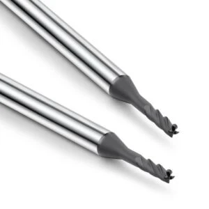
Adjusting Graphite Milling Parameters: How to Reduce Burrs Through Machining Parameters?
When burr issues strike on the shop floor, machinists often rush to replace end mills. However, tooling is rarely the sole culprit. In brittle material processing, tuning graphite milling parameters to match material grain density directly determines edge success. Adjusting spindle speeds, chip loads, and depths of cut with the same tool produces drastically different edge quality.
We once audited a shop producing precision electrodes where tools wore evenly, yet micro-burrs ruined finished edges. The programmer had applied standard metal-cutting feeds, causing erratic force spikes that fractured fragile corners. Successfully optimizing parameters requires balancing tool diameter, graphite density, and feature geometry rather than tweaking isolated settings.
How Does Cutting Speed Affect Burr Formation in Graphite Milling?
Cutting velocity dictates the dynamic engagement between the tool edge and carbon particles. Incorrect cutting speed settings destabilize material removal, causing severe edge tearing or premature tool failure. This balance becomes even more critical when running micro-end mills, where improper speeds compromise both cutting efficiency and surface integrity.
We tune cutting speeds based on graphite shore hardness, tool diameter, and machining phase. Roughing passes require balancing removal rates with tool stability, while finishing operations prioritize sharp edge retention. Matching cutting velocity with the material’s micro-structure ensures clean grain shearing and eliminates residual edge burrs.
How Do Feed Rate and Depth of Cut Affect Graphite Machining Burrs?
Excessive feed rate and depth of cut combinations are primary drivers of edge breakout. Pushing a feed rate too high increases force per tooth, causing unsupported graphite edges to crumble instead of shear. Similarly, an overly aggressive axial depth of cut induces tool deflection, triggering severe chipping on delicate thin walls.
In production environments, we adjust parameters according to localized geometry rather than applying blanket settings. While bulk areas handle aggressive removal, toolpaths approaching final profiles require reduced engagement. Utilizing multiple shallow finishing passes maintains constant cutting pressure, protecting fragile corner profiles and ensuring burr-free accuracy.
How Can Spindle Speed Be Optimized to Improve Graphite Surface Finish?
Fine-tuning your spindle speed is essential for minimizing vibration and optimizing graphite surface finish. Operating at optimal RPM prevents harmonics that cause tool chatter and micro-chipping. If spindle speed mismatches feed rates, surface roughness degrades rapidly—even if dimensional tolerances on the CMM appear correct.
Engineers should evaluate parameter harmony by monitoring spindle load, cutting sound, and surface sheen. During finishing passes, increasing spindle speed while reducing feed per tooth yields a polished surface and pristine edge definition. Is your shop running standard speeds and feeds across all jobs, or are parameters tuned for specific graphite grades?

Graphite End Mill Selection: Choosing the Right Tool to Minimize Burrs in Graphite Machining
In precision graphite component manufacturing, edge quality often hinges on proper graphite end mill selection. While shops sometimes prioritize tool cost or speed, tool geometry compatibility is far more critical for preventing micro-burrs. This holds particularly true in deep-cavity structures and fine electrode contours where cutting dynamics govern edge integrity.
We recently assisted a mold maker using general-purpose carbide end mills for finishing complex electrodes. Although dimensional tolerances were acceptable, micro-fractions persisted along sharp corners. Our analysis proved that the standard cutting edge geometry was incompatible with graphite’s fracture mechanics. Matching tool selection to material grade, cut depth, and feature density is essential for defect-free production.
How Does Graphite End Mill Geometry Affect Cutting Edge Quality?
Variations in graphite end mill geometry—including flute count, helix angle, and relief angles—directly dictate cutting performance. Mismatched edge sharpness or insufficient chip clearance increases cutting resistance, leading to grain crushing and edge chipping. Proper tool design ensures smooth chip evacuation while minimizing mechanical shock to fragile workpiece corners.
On the shop floor, we balance cutting efficiency, edge strength, and chip clearance based on the specific feature being machined. Overly aggressive rake angles may wear prematurely, whereas dull edges crush the material rather than shearing it cleanly. Optimizing cutter geometry for the specific graphite grade ensures stable material removal and eliminates edge defects.
How to Choose Between 2-Flute and 4-Flute Graphite End Mills?
Deciding between 2-Flute and 4-Flute graphite end mills depends entirely on the operational objective. Two-flute end mills feature larger flute valleys, making them ideal for roughing and deep slotting where high-volume dust evacuation is crucial. Conversely, four-flute tools provide superior core stiffness and higher tooth pass frequencies, making them preferred for precision finishing passes.
In high-precision applications, we combine both tool types throughout the process sequence. Roughing passes utilize two-flute end mills for maximum dust clearance, while finishing passes rely on four-flute end mills to minimize vibration and control surface texture. This strategic pairing reduces cutting harmonics and prevents catastrophic edge spalling.
How Does a Sharp Cutting Edge Design Help Minimize Graphite Edge Burrs?
A tailored sharp cutting edge design is vital for preventing edge breakout when machining brittle carbon structures. Because graphite fails through particle fracture rather than continuous chip formation, a dull or improperly hone-prepped edge acts like a hammer, crushing grain boundaries. A razor-sharp, stable edge shears particles cleanly without propagating micro-cracks.
To maintain this sharpness during continuous production, we pair refined edge preparation with specialized diamond coatings. This combination stabilizes cutting forces, prevents premature edge rounding, and ensures clean profile definition. Are your current graphite tools specifically engineered for brittle material removal, or are you using modified metal-cutting designs?

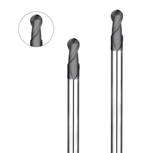
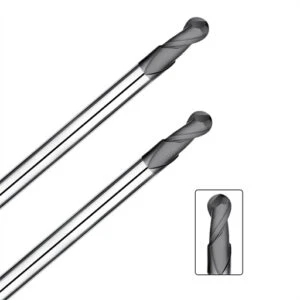
Diamond Coated Graphite End Mills: Tooling Solutions to Enhance Graphite Machining Quality
In continuous graphite electrode and mold component production, abrasive wear remains a top threat to process stability. Machining high-density graphite rapidly degrades uncoated tool geometries over time. As cutting forces rise, workpiece edges chip, tolerances drift, and surface finish quality deteriorates across high-volume production batches.
We recently audited a shop running volume graphite electrodes where early parts passed inspection, but micro-chipping flared up as tooling degraded. The root cause was poor tool wear resistance under continuous friction. Transitioning to diamond coated graphite end mills stabilized cutting mechanics far better than merely adjusting speeds and feeds on worn carbide cutters.
How Do Diamond Coated Graphite End Mills Reduce Tool Wear?
Tool degradation in graphite milling stems from abrasive micro-powder constantly rubbing the cutting edge at high speeds. Uncoated carbide end mills rapidly develop flank wear, dulling the edge and increasing mechanical crushing. Implementing high-hardness diamond films helps reduce tool wear by providing an ultra-hard barrier against continuous particle abrasion.
These specialized end mills leverage extreme surface hardness to maintain sharp edge geometry through extended cutting cycles. However, tool longevity depends on more than coating hardness alone; substrate selection, edge preparation, and coating adhesion strength are equally vital. Matching these factors to your machining parameters ensures predictable performance over long production runs.
How Does Diamond Coating Improve Graphite Surface Finish?
Maintaining tight surface roughness targets requires a sharp, stable cutting profile that resists edge rounding. As standard end mills wear, the cutting mechanism shifts from shearing to abrasive rubbing, creating heavy tool marks and localized surface breakout. In precision EDM electrode production, maintaining edge integrity directly governs final cavity quality.
Under proper machining conditions, applying a high-quality diamond coating prevents rapid edge breakdown and preserves target graphite surface finish specs. However, diamond coatings are not a magic fix for underlying process flaws. If machine vibration, improper feed rates, or poor dust control exist, tooling upgrades alone will not eliminate quality defects.
How to Choose a Reliable Diamond Coated Graphite End Mill Manufacturer?
Selecting a tooling vendor requires evaluating technical expertise rather than comparing purchase prices alone. A qualified supplier must demonstrate strict coating process control, proper micro-grain substrate selection, and deep application engineering knowledge. Their ability to match tool geometries to specific graphite densities determines long-term shop floor success.
When evaluating a diamond coated graphite end mill manufacturer, look for suppliers offering application-specific advice, custom edge preparations, and test tooling validation. Reliable partners evaluate your entire process—including dust extraction, toolpaths, and machine rigidity—to solve burr and wear issues. Is your current tool supplier selling off-the-shelf end mills, or providing engineered solutions tailored to your graphite operations?
Optimizing the Graphite Machining System: Establishing a Stable, Burr-Free Process
Achieving consistent, burr-free graphite parts requires more than tuning isolated variables. Tooling geometries, toolpath logic, parameters, and machine stability constantly interact on the shop floor. Even with a brand-new diamond-coated tool, an erratic toolpath will chip sharp edges. Conversely, optimized feeds cannot overcome spindle runout or inadequate workholding rigidity.
Successfully optimizing the graphite machining system means aligning every link in the production chain. Engineers machining precision EDM electrodes or complex mold inserts must evaluate their workflow holistically: Is the tool geometry matched to the material grade? Are parameters tuned for feature geometry? Can machine rigidity support smooth cutting forces? Resolving these details guarantees reliable, repeatable quality.
How Does CNC Machine Setup Support High-Quality Graphite Machining?
Many edge defects originate from machine stability limitations rather than programming errors. Brittle graphite is exceptionally sensitive to micro-vibration and dynamic cutting force fluctuations. When machining deep cavities or thin ribs, verifying spindle accuracy, tool overhang, fixture rigidity, and axis acceleration tuning is critical.
A proper CNC machine setup provides the dampening needed for continuous material removal. Minimizing tool projection, securing workholding, and verifying spindle runout eliminate abnormal vibrations that shatter fragile corners. Maintaining high machine stiffness ensures smooth cutting passes, preventing edge chipping and preserving tight surface tolerances across batch production.
How Does Graphite Dust Control Reduce Machining Defects?
Graphite dust evacuation is a critical process variable often overlooked by shop managers. Abrasive carbon dust packing into the cutting zone alters chip loads, accelerates tool wear, and degrades surface finishes. Implementing effective graphite dust control directly protects both workpiece quality and machine component longevity.
High-efficiency vacuum extraction keeps the cut zone clear, preventing abrasive dust re-cutting and thermal buildup. Effective suction maintains predictable tool-to-workpiece contact, reducing premature edge rounding and surface scratching. In high-volume production, dust management is not merely housekeeping—it is an essential quality control mechanism.
How Do Tools, Parameters, and Equipment Combine to Form a Complete Graphite Machining System?
Achieving reliable precision requires establishing a complete graphite machining system where tools, parameters, and machine mechanics work in harmony. Upgrading end mills or tweaking feed rates in isolation rarely yields long-term success. The most effective approach is engineering an integrated process tailored to your specific graphite grade and part geometry.
If you are currently troubleshooting recurring edge burrs, erratic tool life, or poor surface finishes, audit your overall process setup. Are your tools engineered specifically for graphite’s brittle fracture mechanics? Do your toolpath parameters maintain uniform chip loads? In your current shop setup, what is the main bottleneck limiting edge quality—tooling, parameters, or overall system coordination?
FAQ: Graphite Machining Burrs
Throughout years of supporting precision mold makers and electrode manufacturers, edge defects and surface finish inconsistencies remain top engineering challenges. Uncontrolled edge chipping during finishing rarely stems from a single failure point. Instead, it is the cumulative result of material brittle fracture, tool degradation, parameter mismatches, and unoptimized toolpath routines.
This FAQ addresses common shop-floor questions based on real-world machining engineering experience. You will find actionable insights covering root causes of burrs, process optimization tactics, tool selection logic, and the real impact of diamond coatings. Use these expert solutions to audit your current equipment, material grades, and parameters for cleaner edge results.
Why Does CNC Graphite Machining Create Burrs?
In brittle carbon materials, a graphite machining burr is not ductile flash like on aluminum or steel; it is a localized fracture defect. Because graphite lacks plastic deformation, material removal occurs through micro-cracking and particle detachment. When cutting forces surge or tools dull, localized stress concentration causes carbon grains to shatter unevenly along unsupported edges.
Preventing edge breakout requires auditing cutting forces, tool sharpness, and corner engagement toolpaths. High feed rates, excessive depths of cut, improper climb milling setups, and spindle runout severely exacerbate edge spalling. Maintaining a constant chip load and utilizing sharp tool geometries prevent brittle fracture along delicate profile margins.
How to Reduce Graphite Edge Burrs During CNC Machining?
To reduce graphite edge burrs, engineers must optimize the entire machining sequence rather than relying on manual post-processing. Start by refining stock allowances between roughing and finishing operations to ensure uniform cutting loads. Always implement arc-filtered entry methods and roll-in corner routines to prevent abrupt force spikes as tools transition into edges.
In shop-floor practice, maintaining tool sharpness, controlling feed per tooth, and optimizing dust extraction are critical. Smooth CAM toolpath transitions prevent micro-fracturing along sharp corners and fragile ribs. Additionally, ensuring machine tool rigidity and minimizing spindle runout eliminates abnormal chatter that triggers catastrophic edge chipping.
Which Graphite End Mill is Best for Burr Free Graphite Machining?
Achieving burr free graphite machining requires selecting end mills based on specific part geometry and graphite density. There is no single universal cutter for every operation. Small electrodes require razor-sharp edges and high relief angles, whereas deep cavity slotting demands maximum core stiffness and high-volume dust clearance.
Evaluate flute count, core strength, helix angles, and coating types for each machining phase. Two-flute end mills excel at roughing and deep slotting by providing superior dust clearance. Four-flute end mills offer higher core rigidity and tooth pass frequencies, making them ideal for high-precision finishing passes.
Can a Diamond Coated Graphite End Mill Improve Graphite Surface Finish?
Implementing a diamond coated graphite end mill significantly enhances edge stability and surface quality in long production runs. Highly abrasive graphite dust rapidly rounds uncoated carbide edges, shifting cutting dynamics from clean shearing to abrasive rubbing. Ultra-hard diamond films preserve cutting edge geometry, preventing edge degradation over time.
However, a diamond coating cannot compensate for bad machining parameters or flexible setups. If toolpaths cause chatter, feeds are incorrect, or dust vacuuming is inadequate, surface defects will persist. A diamond coating works best when integrated into an already optimized machining system with stable fixtures and precise parameter settings.






