


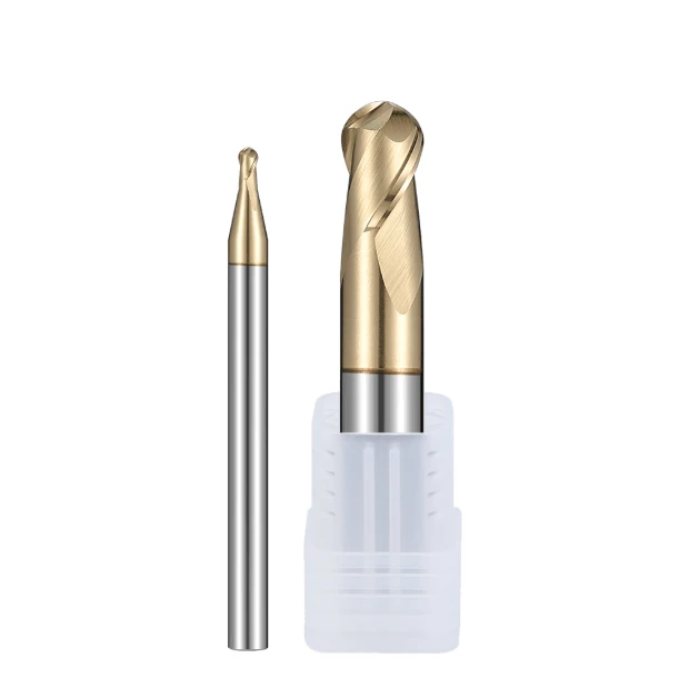
Over the past decade, we’ve taken weekly urgent calls from shops facing the same nightmare: severe chatter during the finish milling of stainless steel contours. The finished parts end up covered in wavy marks and “orange peel” textures, while carbide tools suffer micro-chipping in under 30 minutes.
This isn’t an isolated problem. Whether you’re machining 316L medical implants or 17-4PH aerospace valve bodies, eliminating chatter when using an end mill ball nose for stainless steel is a constant battle. Simply dropping the feed rate often backfires on austenitic stainless, forcing the cutting edge to rub against the work-hardened layer, spiking cutting forces and driving up resonance.
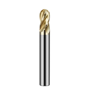
Solving chatter requires fixing the underlying root causes: tool geometry (like switching to a 2 flutes end mill for stainless steel to improve chip evacuation), centerline cutting speed compensation, and tool runout control.
In our factory, we’ve tested dozens of edge-honing methods on 5-axis grinders and fine-tuned cutting parameters on customer shop floors. From picking high-rigidity solid carbide ball nose end mill substrates to choosing the right best end mill coating for stainless steel, stopping vibration requires a complete, systematic process.
As a dedicated carbide end mill for stainless steel factory, we know the pressure Western machine shops face regarding cost and cycle times. Even when using a cost-effective china ball nose end mill, you won’t get the rigidity you paid for without the right strategies, like tool tilting and dynamic toolpaths. Are you facing these same surface finish issues in your shop?
Why Does Chatter Occur So Easily When Machining Stainless Steel with Carbide Ball Nose End Mills?
In our testing facilities and customer production lines, chatter during stainless steel 3D milling remains our most frequent troubleshooting request. Engineers often wonder why even a rigid carbide ball nose end mill creates a harsh, high-pitched buzz the moment it touches the workpiece. Based on our years of cut-data tracking, this issue does not stem from a soft tool, but rather a violent physical conflict between stainless steel’s high ductility and the cutter’s geometry.
Chatter is the inevitable result of fluctuating cutting forces, poor thermal conductivity, and structural compliance acting together. When cutting sticky materials like 304 or 316, cutting resistance surges rapidly. If you do not analyze the dynamic force state at the tool tip, simply dropping spindle speed or depth of cut will fail to eliminate this self-excited vibration.
Sharp Spikes in Cutting Resistance and Self Excited Vibration Caused By the “Zero Cutting Speed” Zone at the Ball Nose Tip
We have analyzed tool tip wear under microscopes hundreds of times, and the core problem always starts at the dead center. When running an end mill ball nose for stainless steel on flat or shallow surfaces, the surface feet per minute (SFM) at the absolute tip drops to zero. Instead of shearing cleanly, the tool forcibly extrudes and scrapes the metal, causing massive axial force spikes.
This intense center-zone extrusion instantly disrupts system equilibrium. In our force-dynamometer data, axial force fluctuations at zero speed regularly trigger self-excited chatter between the spindle and workpiece. Unless you tilt the tool axis to move this physical “blind spot” away from the cut, no amount of coolant or feed adjustment will smooth out the ride.
The Impact of Work Hardening in Austenitic Stainless Steel (304/316) on Carbide Ball Nose End Mill Edges
Austenitic grades like 304 and 316 give machine shops the biggest headaches because of their rapid work-hardening behavior. When running a carbide ball nose end mill, the heavy plastic deformation from the previous tooth sweep leaves an ultra-hard surface layer. If the following tooth engages within this zone, it continuously smashes into a crust far harder than the base metal.
This continuous impact subjects the carbide edge to severe mechanical shock. If your feed per tooth is too light, the edge spends more time rubbing, generating localized heat that fuses material onto the rake face to form a Built-Up Edge (BUE). As this BUE repeatedly forms and breaks off, it creates violent force spikes that quickly lead to micro-chipping and chatter.
Resonant Superposition Caused by Excessive Tool Overhang (L/D Ratio) and Insufficient Clamping Rigidity
Often, chatter is not just a tool issue, but a system rigidity bottleneck amplified at the cutter tip. When profiling deep cavities or tall walls, engineers are forced to use long-reach tools. Our bending-stress calculations show that doubling tool overhang reduces tip stiffness cubically, making metric ball nose end mills deflect under heavy cutting loads.
Beyond tool reach, holder runout and clamping style are frequently overlooked. During shop diagnostics, we regularly find standard ER collets holding long-reach ball nose cutters with runout exceeding 0.01mm. When high overhang combines with holder runout, it triggers severe harmonic resonance at specific speeds, leaving wave patterns and destroying cutter life.
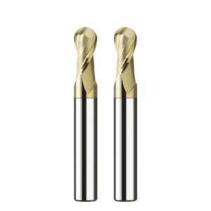
Selecting Tool Structures to Suppress Chatter: Balancing Chip Evacuation and Rigidity in 2 Flutes End Mills for Stainless Steel
When fighting chatter on stainless steel contours, an engineer’s first instinct is often to add more flutes for extra tool core strength. However, our shop tests prove this frequently backfires. Tool selection is always a balance between chip gullet capacity and core rigidity. Because stainless steel chips are gummy and continuous, multi-flute tools easily clog, causing force surges and self-excited chatter.
When designing cutters for heat-resistant alloys, we prioritize tailored geometry over raw flute count. By optimizing chip gullets, incorporating non-symmetrical features, and fine-tuning neck relief, we maximize chip flow without sacrificing core strength. This structural optimization breaks resonance conditions at the source, laying a solid foundation for stable parameter tuning.
Why Do We Prioritize Recommending 2 Flutes End Mills for Stainless Steel When Machining Deep Cavities and Narrow Slots?
When troubleshooting chatter inside deep mold cavities or narrow slots, the first thing we check is chip packing. In these confined spaces, a 2 flutes end mill for stainless steel provides vastly superior chip gullet volume compared to 4-flute alternatives. This space lets tough chips curl smoothly and evacuate before they get recut and wedge the tool body.
Although a 2-flute tool has a slightly smaller core than a 4-flute tool, its free-cutting action dramatically lowers peak cutting resistance. In real-world cutting, predictable force levels suppress vibration far better than static core thickness alone. When deep-cavity chip packing and chatter strike at the same time, sacrificing flute count for chip clearance is always the smarter engineering choice.
How Unequal Indexing and Variable Helix Angles Disrupt Chatter Frequencies
Standard ball nose cutters with equal flute spacing hit the workpiece at perfectly uniform time intervals, creating periodic impact forces that easily lock into harmony with the spindle’s natural frequency. To break this, our carbide ball nose end mill designs incorporate unequal flute indexing and variable helix angles. By altering the circumferential spacing and changing the helix angle along the flute, cutting impact timing becomes irregular.
This variable-geometry design scatters impact energy across a wide frequency band rather than concentrating it at one pitch. Machine shops testing these anti-chatter geometries report that the sharp, screaming resonance immediately softens into a dull, quiet hum. The workpiece finish shifts from wavy lines to clean, uniform cross-hatching, proving the harmonic feedback loop was broken.
Amplitude Control via Neck Relief Design in Long-Overhang Stainless Steel Surface Machining
When profiling deep stainless steel walls or deep pocket features, using cutters with a ground neck relief is one of the most effective ways to tame long-reach vibration. Running a full-flute cutter inside a deep cavity risks subtle sidewall rubbing, which instantly triggers high-frequency chatter. In contrast, using metric ball nose end mills with a relieved neck keeps only the necessary flute length active, eliminating unwanted friction.
Shortening effective flute length while polishing the neck transition radius directs cutting forces straight up into the spindle taper. During field setups, fine-tuning the stepped neck profile maintains shank rigidity while visibly shrinking deflection amplitude at the tool tip. This extra stability margin is essential for chatter-free 3D profiling at high depth-to-diameter ratios.

On-Site Cutting Parameter and CAM Toolpath Tuning
Once you choose a suitable tool geometry, the final step to eliminate chatter lies in fine-tuning your on-site cutting parameters and CAM toolpaths. We often see workshops use standard flat-bottom programming logic when running ball nose cutters on stainless steel. This mismatch causes severe cutting force spikes, amplifying minor spindle harmonics into visible surface waves on the workpiece.
Fixing chatter is never as simple as blindly dropping your spindle speed or axial depth of cut. By optimizing the tool axis tilt angle, recalculating actual cutting speeds, and matching step-overs with feed rates, you can actively avoid chatter-prone zones. This dual strategy keeps cutting resistance low, enabling stable, chatter-free machining without sacrificing cycle times.
Tilted Tool-Axis Cutting (15°–20°): Avoiding the Ball-Nose Center Point to Increase Actual Cutting Speed
When machining flat surfaces or shallow cavity bottoms, conventional 3-axis vertical toolpaths create a zero-linear-speed zone at the tool tip that triggers severe chatter. Tilting the tool axis by 15° to 20°—either along the feed direction or laterally—shifts the active cutting zone away from the dead center. Using an end mill ball nose for stainless steel at an angle moves engagement to the higher-speed side of the ball.
This tilt angle instantly converts axial crushing forces into radial forces that the spindle can absorb more efficiently. By avoiding the zero-velocity tip, material shearing becomes smoother without severe chip compaction. On-site vibration sensors show that tilting the tool axis alone can drop force pulse amplitudes by over 40%, completely silencing piercing resonance.
Feed Rate and Step-over Compensation: Avoiding Chatter Thresholds with Metric Ball Nose End Mills
Programmers frequently overlook the chip thinning effect when running ball nose cutters on light-load passes. When finishing with a small step-over, the actual chip thickness is far lighter than the programmed feed per tooth, causing the edge to rub against the hardened layer and induce chatter. When running high-precision metric ball nose end mills, you must calculate the effective cutting diameter and apply a feed rate multiplier.
Balancing step-over with your axial depth of cut is equally critical for dodging harmonic thresholds. If your machine enters resonance at a specific engagement angle, making a minor 5% to 10% adjustment to the step-over alters the tooth impact timing. This subtle shift breaks the chatter energy buildup much more effectively than taking a massive hit on overall productivity.
Real-World Performance of Climb Milling and Dynamic Motion in Reducing Cutting Forces
Toolpath direction dictates how cutting forces impact the edge upon entry. We consistently advocate climb milling because the edge engages the material at maximum chip thickness and tapers to zero. This thick-to-thin cutting action lets the edge bite immediately, preventing the violent skidding and rubbing that conventional up-milling causes on work-hardened surfaces.
Combining constant-engagement CAM paths with the generous chip clearance of a 2 flutes end mill for stainless steel takes force control to the next level. Dynamic toolpaths maintain a fixed arc of contact through sharp corners, preventing massive force spikes. This combination clears sticky chips rapidly while dampening peak cutting resistance right at the source.
Coating and Substrate Synergy: How the Best End Mill Coatings for Stainless Steel Indirectly Mitigate Vibration
Supervisors often focus solely on machine rigidity and feeds, ignoring how tool coatings and substrates impact dynamic stability. Coatings do far more than resist wear; by altering physical friction and heat transfer during the cut, they act as indirect vibration dampers. Low frictional resistance stabilizes cutting force amplitudes, preventing the system from locking into resonance.
Stainless steel’s low thermal conductivity creates intense thermo-mechanical adhesion on the tool’s rake face, leading to unstable force spikes. Selecting the best end mill coating for stainless steel pairs a slick nano-coating with a high-toughness substrate. This combination absorbs micro-vibration stress, ensuring a smoother machining process on gummy alloys.
Reducing the Friction Coefficient: Why Lowering Cutting Heat Prevents Secondary Vibration Caused by Built-Up Edge (BUE)
During austenitic stainless steel finishing, high heat and pressure readily cause material to weld onto the rake face. Under microscopic observation, we see sticky particles weld to the tool and tear away under chip flow. This violent growth-and-detachment cycle constantly alters the effective rake angle, creating secondary force impacts that trigger chatter.
To break this vicious cycle, silicon/chromium-based nanocomposite coatings offer extreme high-temperature lubricity and anti-adhesion properties. A slippery coating lets hot chips slide off the rake face effortlessly, keeping heat out of the cutter body. Keeping temperatures below the adhesion threshold prevents BUE formation, stabilizing force fluctuations and eliminating heat-induced chatter.
Comparative Test Data: Analyzing the Vibration Resistance of Premium Stainless Steel End Mill Coatings in Dry vs. Wet Machining
Whether dry or wet machining is better for stainless steel depends on matching the cooling style to the coating’s oxidation traits. Traditional flood cooling subjects the coating to high-frequency thermal shocks during interrupted cuts, causing micro-cracks that lead to edge chipping. Conversely, utilizing high-pressure air cooling or MQL lets the best end mill coating for stainless steel perform at its peak.
Under high-pressure air cooling, a protective oxide film forms on the slick coating surface. Test data shows force fluctuation dispersion drops by nearly 30% compared to wet flood cooling, lowering resonance risks. However, on deep-cavity 316L jobs, high-pressure internal coolant remains essential for flushing chips and preventing severe packing chatter.
Enhancing Chipping Resistance Under Micro-Vibration with Ultrafine-Grain Carbide Substrates
Absolute zero vibration is impossible under every real-world setup, making substrate toughness your final line of defense. Factories that blindly choose coarse-grained, brittle carbide grades suffer from microscopic edge chipping under micro-vibration. These damaged edges rapidly amplify chatter amplitude, creating a vicious cycle that ruins surface finishes.
When grinding a premium carbide ball nose end mill, we select nano-grade carbide substrates with 0.2 to 0.5 μm grain sizes and strictly controlled cobalt distribution. This microstructure imparts exceptional flexural strength and fracture toughness. Even under high-frequency micro-vibrations during long-overhang jobs, the tough substrate absorbs stress impacts, preserving edge integrity and keeping cutting forces flat.

Supply Chain & Procurement in Practice: Sourcing High-Rigidity Custom Tools from a Carbide End Mill Factory for Stainless Steel
Over a decade of collaborating with high-end shops, we have learned that adjusting machine parameters alone cannot fix severe chatter. Often, vibration issues are built directly into the cutter during manufacturing. As a dedicated carbide end mill for stainless steel factory, we regularly reverse-engineer tool parameters using shop-floor vibration data, translating field feedback into precise grinding standards to match your required rigidity.
Procuring high-performance cutters requires deep technical collaboration, not just ordering from a catalog. Microscopic edge preparation, micron-level runout control, and grinder wheel wear compensation all dictate how a cutter behaves under heavy loads. Establishing strict manufacturing specifications and quality standards ensures every tool delivered to your shop floor maintains exceptional stability.
How European and US Clients Specify Edge Honing (Edge Prep) for Stainless Steel Carbide End Mills
When specifying custom tools for tough alloys, edge preparation is always a key discussion point. Buyers new to stainless steel often think a razor-sharp edge cuts best, but un-passivated edges quickly micro-chip under high cutting forces, triggering severe chatter. As a specialized carbide end mill for stainless steel factory, we use 5-axis grinders with nylon brushing or fluid polishing to apply a precise 5μm to 15μm micro-radius (K-Land or honed edge).
This micro-radius strengthens the cutting edge without increasing cutting resistance, preventing stress concentration on fragile tips. Experienced procurement engineers explicitly define passivation profiles on tool prints as their first line of defense against work-hardening impacts. Precise edge-honing control is what separates basic off-the-shelf cutters from high-end, chatter-resistant custom tools.
Requirements for Runout Control (TIR < 0.005mm) in High-Precision Metric Ball Nose End Mills for Mold Machining
In precision medical or aerospace mold making, minute radial runout causes centrifugal force fluctuations that leave severe chatter marks. When running high-precision metric ball nose end mills for mirror-finish finishing, total indicated runout (TIR) must stay under 0.005mm. If runout hits 0.01mm, a single tooth carries the workload, triggering high-frequency harmonic resonance.
Achieving sub-0.005mm TIR across the full tool length requires premium carbide blanks and hydraulic chucking during grinding. When setting up incoming quality control (IQC) procedures, we recommend measuring runout at three times the diameter using an optical presetter. Ensuring equal chip load across all flutes is essential for maintaining smooth cutting forces and stopping periodic vibration at the source.
Evaluating the Grinding Precision and Batch Consistency of Chinese-Made Ball Nose End Mills: Interpreting ANCA/Rollomatic Inspection Reports
Cost-effective Chinese tools have earned a solid place in global supply chains, but batch consistency remains a primary concern for buyers. When evaluating a china ball nose end mill, look past marketing brochures and request raw grinding files from ANCA or Rollomatic grinders, alongside batch data from Zoller inspection systems. These reports reveal exact variances in relief angles, helix consistency, and ball radius tolerances.
Focusing on key metrics—like ball profile accuracy within ±0.005mm and mirror-finish flank grinding—tells you if the supplier uses proper wheel wear compensation. Inconsistent relief angles across a batch cause unpredictable cutting forces, leading to premature chatter on the floor. Verifying raw grinding data is a core skill for procurement teams sourcing reliable, vibration-free tooling.
Case Studies of Stainless Steel Chatter Issues with Western Clients and a Quick-Fix On-Site Troubleshooting Checklist
Resolving chatter on stainless steel contours requires a systematic approach covering geometry, toolpaths, workholding, and tool quality. When a spindle starts screaming, operators need an immediate, logical workflow rather than blind speed or feed reductions. By translating cutting mechanics into shop-floor troubleshooting steps, you can rapidly pinpoint vibration sources and restore process stability.
Over years of field service, we have refined a structured diagnostic routine that isolates hardware and software issues within minutes. Most chatter stems from a compounding effect of runout, toolpath choice, and edge prep reaching a critical threshold. Applying this systematic checklist lets you eliminate vibration without halting production or wasting expensive workpieces.
Eliminating Chatter Marks on 316L Parts for a US Medical Device Client Using a Chinese Ball Nose End Mill
A California medical manufacturer mass-producing 316L parts on 5-axis centers suffered severe wavy chatter marks using an end mill ball nose for stainless steel. Pass rates for Ra 0.4μm surface requirements dropped below 60%, leading the shop to suspect their china ball nose end mill lacked rigidity. Upon reviewing their CAM paths and Zoller reports, we identified three root causes: vertical 3-axis toolpaths causing zero-speed rubbing, 0.012mm collet runout, and an undersized feed rate inducing work hardening.
We applied a three-step fix: tilting the tool axis 15° to avoid the dead tip, switching to a shrink-fit holder to drop runout under 0.003mm, and increasing feed per tooth by 25% under high-pressure MQL. Without changing the cutter brand, cutting noise vanished and surface finishes reached Ra 0.3μm. Eliminating chatter nearly doubled tool life, proving that proper setups allow cost-effective cutters to deliver flawless surface finishes.
5-Minute Workshop Troubleshooting Checklist: Rapid Diagnosis from Toolholder Runout and Coolant Pressure to Axial Depth of Cut (Ap)
When you hear high-pitched resonance during stainless steel contouring, follow this 5-minute Quick-Fix checklist before stopping the job:
-
Minute 1 (Check Clamping Runout): Measure TIR at 3X diameter using a dial indicator. If runout exceeds 0.005mm, clean your collet or switch to shrink-fit or hydraulic toolholders to keep carbide ball nose end mill engagement balanced.
-
Minute 2 (Verify Engagement Angle): Check if your toolpath hits the zero-speed center point. On flat surfaces, tilt the tool axis 15° or adjust step-over by 10% to disrupt harmonic feedback.
-
Minute 3 (Inspect Chip Evacuation & Coolant): Ensure chips curl smoothly without purple discoloration. If chips pack in cavities, boost coolant pressure or switch to through-spindle coolant to flush recut chips instantly.
-
Minute 4 (Recalculate Chip Thickness): Check if chip thinning is causing edge rubbing on work-hardened layers. Increase feed per tooth 15% to 20% to force edges to bite beneath the hard surface.
-
Minute 5 (Adjust Axial Depth of Cut, Ap): On long-reach setups, reduce axial depth of cut (Ap) by 20% while increasing feed rate. This shallow-cut, high-feed method lowers cutting resistance and stops chatter.
If you face stubborn resonance on gummy alloys or deep cavities, review your setup against this checklist. Feel free to share your part prints, material grades, or current parameters with our engineering team—we are always ready to help you optimize your tooling and eliminate chatter on your floor.






