In our tool manufacturing workshop, we receive urgent emails almost weekly from machine shops in the US and Europe. A typical scenario involves batch processing 316L stainless steel medical valves or aerospace fittings, where blueprints specify a tight radius for clearing internal cavity roots. However, when QC inspects the parts using a contour tracer, they discover that the perfect arc—which should have been defined by the end mill corner radius for stainless steel—has become an irregular, out-of-tolerance surface.
Many shop supervisors immediately blame the tool manufacturer, questioning if the carbide corner radius end mill dimensions were off-spec. Yet, when we analyze their machining videos, tool overhang, and cutting data, the issue invariably points to the same silent killer: tool deflection.
Anyone in the industry knows just how troublesome machining stainless steel can be. Its extreme stickiness and work-hardening characteristics generate radial cutting forces that far exceed those of ordinary carbon steel. When using a stainless steel end mill for deep-cavity side milling, even a slight increase in the overhang-to-diameter ratio allows massive lateral forces to physically push the tool away.
This minute deflection—often invisible to the naked eye—causes the actual path of your CNC corner radius milling tools to deviate from the programmed route. After tracking hundreds of cases for shops that buy wholesale corner radius end mills, we found that 90% of premature tool tip failure stems from a failure to control this deflection, not from the coating or substrate itself.
As a fellow professional, do you frequently encounter this baffling phenomenon where the tool dimensions are perfect, yet the part’s corner radius fails inspection, forcing you to rely on frequent tool changes just to meet deadlines?
Why Does the Work Hardening of Stainless Steel Cause Severe Tool Deflection When Using Carbide Corner Radius End Mills?
Last month, a UK precision machine shop supplying European medical device manufacturers contacted us regarding a major issue. While machining a batch of 316L stainless steel parts featuring deep cavities, the tight transition radius between the sidewall and the bottom kept falling out of tolerance. The technical supervisor complained that even after reducing the feed rate, their high-performance carbide corner radius end mill still deflected away from the material.
When providing technical support, we frequently emphasize a fundamental workshop principle: the primary challenge with stainless steel isn’t its static hardness, but its intense work-hardening characteristics. If the cutting path hesitates even slightly, the surface left behind by the previous tooth instantly hardens, becoming as tough as high-speed steel. The immense cutting resistance generated by this hardened layer translates into massive radial reaction forces, forcibly pushing the tool away from the workpiece.
The Physical Deflection Effect of Reaction Forces on a Stainless Steel End Mill When Machining 304 and 316
In our daily interactions with machine shops, we find that many operators tend to conflate 304 and 316 stainless steels. In reality, the addition of molybdenum gives 316 significantly higher high-temperature strength and stickiness compared to 304. When a stainless steel end mill engages 316, the material’s poor thermal conductivity prevents heat from escaping through the chips, causing intense thermal accumulation directly at the cutting edge.
This localized heat spike alters the material’s yield strength, resulting in reaction forces that frequently exceed theoretical CAM calculations. For the tool body, this acting force operates as a constant lateral leverage mechanism that worsens when chips pack the flutes. Once this lateral thrust exceeds the clamping rigidity of your spindle and tool holder, the tool tip undergoes micron-level deflection, causing it to micro-bounce against the workpiece.
Assessing the Rigidity Limits of CNC Corner Radius Milling Tools in Long-Overhang Machining
When machining deep cavities or complex housings, we often have to extend the cutter significantly from the holder to avoid tool holder interference. In these long-reach scenarios, looking solely at material hardness is insufficient for assessing the rigidity limits of CNC corner radius milling tools. We typically evaluate the setup based on the classic overhang-to-diameter (L/D) ratio, knowing that bending deflection increases cubically once the overhang exceeds four times the diameter.
The most practical way to assess these rigidity limits is to observe fluctuations in the spindle load meter during the first part’s run and check the positional variance using a dial indicator. If the spindle sound shifts from a crisp hiss to a dull hum, and alternating light and dark chatter marks appear on the wall, you have breached the rigidity critical point. In these instances, we always recommend making a trade-off: sacrifice some axial depth of cut to regain tool stability.
Diagnosing via Chipping Marks: Is Your End Mill Corner Radius for Stainless Steel Cutting or Extruding?
Instead of tossing worn-out cutters straight into the scrap bin, we prefer to examine the microscopic wear marks on the tool tip under 20x magnification. If the radiused cutting edge of your end mill corner radius for stainless steel exhibits uniform flank wear, your cutting parameters are healthy. However, if you observe fine, shell-like chipping or catastrophic edge flaking, it indicates that the tool is no longer cleanly shearing the metal but is instead rubbing and extruding.
This extrusion-style machining is highly destructive because a deflecting tool cannot maintain its intended chip load per tooth. The corner radius essentially polishes the stainless steel under high pressure, which thickens the work-hardened layer and generates intense, localized thermal fatigue. When the subsequent tooth impacts this hardened surface, it triggers micro-chipping, allowing us to accurately diagnose whether your issue is insufficient coating wear resistance or deflection-driven abuse.

How Does Tool Deflection Stealthily Ruin the Corner Radius of End Mills Machining Stainless Steel?
One of the most frustrating workshop scenarios occurs when an operator monitors a process that appears perfectly normal—steady cutting sounds and no machine alarms—only for the part to be rejected by QC. The most insidious aspect of tool deflection when machining stainless steel is its stealthiness. Unlike a dramatic tool breakage, deflection involves subtle, micron-level elastic shifts occurring quietly during the cut, directly altering part geometry and making the critical end mill corner radius for stainless steel the first casualty.
We once investigated an issue for a contract manufacturer whose precision stainless steel valve seats were rejected by overseas clients across three consecutive batches because the transition radii failed print specs. In reality, tool deflection was working in the shadows: lateral cutting forces caused invisible bending deformation in the tool body, creating a deviation between the actual path and the programmed trajectory. The three invisible pitfalls discussed below are typical failure cases identified during QC inspections that we frequently encounter while providing technical support.
Geometric Deviation Between Theoretical and Actual Corner Radiu: Why Did Your R0.5 Turn into an Irregular Residual Arc?
When we program G02 or G03 circular interpolation commands, expecting a carbide corner radius end mill to cut a perfect R0.5 fillet at the base of a stainless steel part, we often overlook dynamic tool-tip deformation. At corners where the radial depth of cut or stepover changes-abruptly, the tool’s engagement angle spikes instantly, causing a sudden surge in cutting resistance. If the rigidity of the tool holder and spindle system cannot withstand this force, the entire tool tilts outward.
When using a profilometer to compare scrapped parts against specifications, we observed that this geometric deviation is particularly severe deep within the part’s corners. Because the tool deflects, the displacement is minimal during straight-line cutting but peaks at the corner point, leaving a smoothly transitioning gradient error on the workpiece surface. Inexperienced process engineers often mistakenly attribute this to an inaccurate tool nose radius or blindly adjust tool offsets, which alters previously correct straight sections until they fall out of tolerance.
How Tool Deflection Intensifies Localized Friction, Causing Premature Thermal Wear at the Tip of a Stainless Steel End Mill
When the tool body bends and deflects under resistance, the contact dynamics between the workpiece and the side and bottom edges of the tool’s corner radius change drastically. The rake and relief angles—designed for efficient chip removal—shift into negative contact angles as the tool tilts, transforming smooth cutting into high-pressure rubbing. For a stainless steel end mill, which has low thermal conductivity, this intensified localized friction is devastating, causing heat to rapidly accumulate at the vulnerable corner radius.
We observed this process in the laboratory using infrared thermal imaging; in areas with severe tool deflection, the temperature at the tool tip spiked to over 800°C within seconds. Such extreme heat causes the tool’s nano-coating to undergo thermal oxidation and flake off, leaving the exposed carbide substrate to suffer from severe diffusion and adhesive wear. This explains why many peers report that the tool tip wears down to a blunt state after traveling only a few meters when cutting stainless steel; the root cause lies entirely in excess localized frictional heat.
Tool-Mark Defects and Excessive Surface Roughness: The #1 Technical Reason European and American Buyers Reject Stainless Steel Parts
Buyers in Western machinery industries have incredibly strict requirements regarding surface roughness (Ra value) and visual finish. When machining intersecting lines or performing multi-axis simultaneous machining on stainless steel, tool marks caused by tool deflection are the primary cause for rejection. When using CNC corner radius milling tools for layered side milling or finishing, variations in cutting resistance between passes cause the tool deflection to fluctuate, leaving visible steps or ripples on the workpiece sidewall.
At a microscopic level, vibration caused by deflection creates periodic scallops or burrs on the workpiece surface. Even if a workshop attempts to mask these marks with a final polishing pass, they cannot escape the scrutiny of high-magnification microscopes or roughness testers used by Western QC teams. Uneven deflection transforms a surface intended for continuous cutting into an uneven, periodic profile, causing the Ra value to skyrocket and forcing us to strictly control deflection within tolerance limits at the planning stage.
How We Completely Solve the CNC Corner Radius Milling Tool Deflection Problem by Optimizing Cutting Strategies
Whenever we conduct on-site technical diagnostics at client workshops, the most common suggestion we hear is: “Since tool deflection is severe, I’ll just cut the spindle speed and feed rate in half.” Frankly, while this conservative approach might work for ordinary steel, it often backfires when machining stainless steel because insufficient cutting force actually exacerbates friction. Over the past decade, we have worked alongside countless frontline programmers to develop a unique, field-tested approach specifically designed to tame the elastic deflection experienced by CNC corner radius milling tools under heavy loads.
The core logic behind solving tool deflection isn’t simply to avoid the force; rather, it involves redirecting the cutting forces by altering how the cutting edge enters and exits the metal. We recommend three specific strategies to high-precision machine shops that require no investment in expensive new machinery. Instead, by optimizing CAM toolpath algorithms and cutting parameter combinations, these methods transform the lateral force that pushes the tool away into a stabilizing force that holds the tool firmly against the workpiece path.
The Decisive Role of Climb Milling in Suppressing Deflection for Carbide Corner Radius End Mills
When milling stainless steel, we almost invariably recommend climb milling. With a carbide corner radius end mill, climb milling causes the chip thickness to transition gradually from maximum to zero. This means the cutting edge bites directly into the workpiece upon entry, avoiding the friction and sliding against a work-hardened surface often seen in conventional up-cut milling. This smooth entry mechanism drastically reduces, at the source, the radial resistance that causes tool deflection.
More importantly, the lateral cutting force generated during climb milling tends to pull the tool body toward the machined surface rather than pushing it away. Comparative tests using multi-axis dynamometers in workshops have shown that conventional milling results in more than three times the lateral deflection of climb milling when machining 316 stainless steel. However, we always remind our peers that climb milling requires a CNC machine with effective backlash compensation, otherwise it can lead to gouging or severe chatter.
Leveraging CAM-Based Trochoidal Milling and the Chip Thinning Effect to Distribute Instantaneous Loads on the End Mill’s Corner Radius
When a tool navigates a right-angled corner or a narrow slot within a cavity, the engagement angle can instantly spike from 45 degrees to 180 degrees; this sudden full-engagement cutting is the primary cause of corner radius failure. To protect the vulnerable end mill corner radius for stainless steel, we strongly advocate for dynamic trochoidal milling paths found in modern CAM software. By utilizing dense, rolling circular toolpaths, this strategy ensures a constant, minimal radial engagement angle when entering corners, effectively distributing high instantaneous loads.
Under these dynamic toolpaths, the radial depth of cut is typically less than 10% of the tool diameter, triggering the classic chip thinning effect. Since the actual chip thickness is significantly less than the programmed feed per tooth, we can substantially increase the feed rate. This allows cutting heat to be carried away by the high-speed chips before it can conduct into the tool’s corner radius, minimizing tool deflection caused by thermal expansion and enabling efficient roughing of stainless steel.
Dynamically Optimizing the Ratio of Axial Depth of Cut (Ap) to Radial Depth of Cut (Ae) to Keep Tool Deflection Under 0.01mm
When facing tool deflection issues during deep cavity machining, many in the industry habitually use shallow axial depths of cut (Ap), skimming off material layer by layer; however, this practice concentrates the entire cutting load onto the tool’s bottom corner radius. When setting up processes for precision stainless steel housings, we prefer a “high axial, low radial” parameter combination. We aim to maximize the axial depth of cut—extending it to 1.5 to 2 times the flute length—while reducing the radial step-over (Ae) to approximately 5% of the tool diameter, allowing the entire side edge to engage.
By dynamically fine-tuning the ratio between these two factors, we can strictly limit lateral deflection to within 0.01 mm, which is critical for ensuring perpendicularity and corner radius consistency in high-precision parts. Of course, this deep-cutting strategy places extremely high demands on the flute design of your wholesale corner radius end mills and on coolant pressure. If your internal coolant pressure falls below 70 bar, or if chip clearance space is insufficient, you must compromise on the depth of cut to ensure process safety.
Mitigating Risk at the Source: Structural Rigidity Enhancements in Our Wholesale Corner Radius End Mills
We have previously discussed adjustment strategies regarding CNC machine setups and programming processes. However, seasoned professionals know that if the tool’s inherent physical rigidity and geometric structure are fundamentally weak, subsequent parameter optimizations merely treat the symptoms rather than the root cause. As a tool manufacturer providing technical support to demanding Western shops, our focus is delivering superior physical resistance to tool deflection right at the source of production for clients purchasing wholesale corner radius end mills.
For us manufacturers, even the slightest dimensional deviation during your mass production translates into a quality risk affecting hundreds or thousands of parts. To minimize deflection before the tools even leave the factory, we have adopted structural designs that align more effectively with the cutting mechanics of stainless steel. If you are frustrated by the tedious processes of re-zeroing and adjusting tool offsets after tool changes—caused by inconsistent rigidity in bulk-purchased tools—we invite you to compare your tooling against our manufacturing improvements.
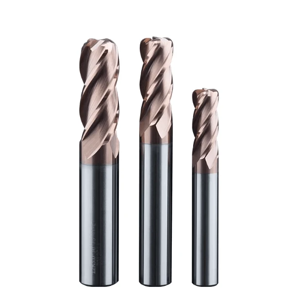
Boosting Flexural Strength with Micro-Grain Carbide Substrates Tailored for Stainless Steel
When selecting a carbide corner radius end mill, many technicians focus solely on the grade and hardness (HRA). However, the rigidity of solid carbide tools depends fundamentally on the microscopic grain size within the substrate. We have moved away from traditional coarse-grained materials in our formulations, opting instead for micro-grain and nano-grade tungsten carbide substrates specifically engineered for difficult-to-machine materials.
This enhanced Transverse Rupture Strength (TRS) translates directly into superior resistance against lateral elastic deformation. When facing sudden radial impact loads caused by the instantaneous work-hardening characteristic of stainless steel, the ultra-fine-grained matrix effectively withstands the thrust force and minimizes tool deflection. If you are grappling with challenges such as high length-to-diameter ratios or corner chipping during deep-cavity root cleaning, this high-TRS matrix will provide a more robust support for the tool.
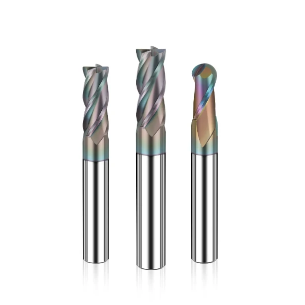
Proven Effectiveness of Variable Helix and Variable Pitch Geometries in Suppressing Chatter During Stainless Steel Machining
Tool deflection and chatter are constant companions; when a stainless steel end mill deflects during cutting, it inevitably triggers periodic resonance, leaving fine chatter marks on the workpiece surface. To disrupt the resonance caused by the periodic overlapping of cutting forces, we have implemented asymmetric modifications to the cutting edges. By utilizing variable helix angles and variable pitch geometry, we ensure that the timing of engagement and the direction of cutting forces differ for each cutting edge.
In our tests, this structural design demonstrated remarkable vibration-damping capabilities. Before a vibration wave generated by the first edge could fully form, the subsequent edge—operating at a different angle—physically interrupted and neutralized the wave peak. If you are currently using standard constant-helix end mills to machine thin-walled stainless steel aerospace components, switching to a tool with this variable geometry offers a reliable solution to maintain high feed rates and surface finish.
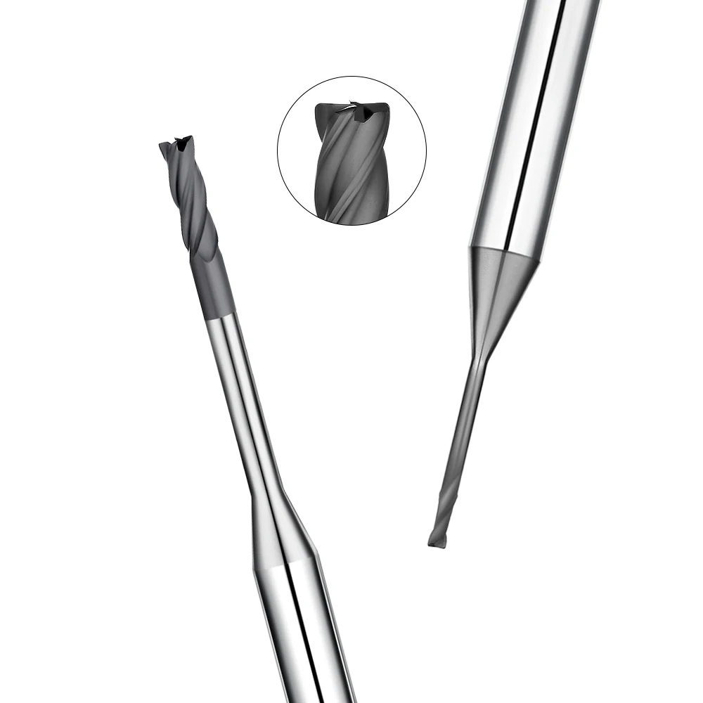
Customizing Key Parameters Based on the Overhang-to-Diameter Ratio for Bulk Orders of Corner Radius End Mills
When handling large-scale custom orders, we advise against simply placing orders based on standard product catalogs. Shop-floor machining conditions vary widely; factors such as spindle dynamic balance, workholding rigidity, and the tool’s overhang-to-diameter ratio dictate the specific flute depth and core diameter required. Using a standard-core end mill for long-overhang machining often results in insufficient cross-sectional area, making the tool highly susceptible to geometric errors.
Therefore, before finalizing a procurement plan for wholesale corner radius end mills, we recommend in-depth technical alignment. If you are currently evaluating specifications for your next batch of stainless-steel-specific cutters, we invite you to discuss your specific machining conditions, part drawing tolerances, or your particular stainless steel grades. By sharing these real-world shop-floor challenges, we can strike the optimal balance between flute chip-clearance space and core thickness to minimize the risk of tool deflection.