


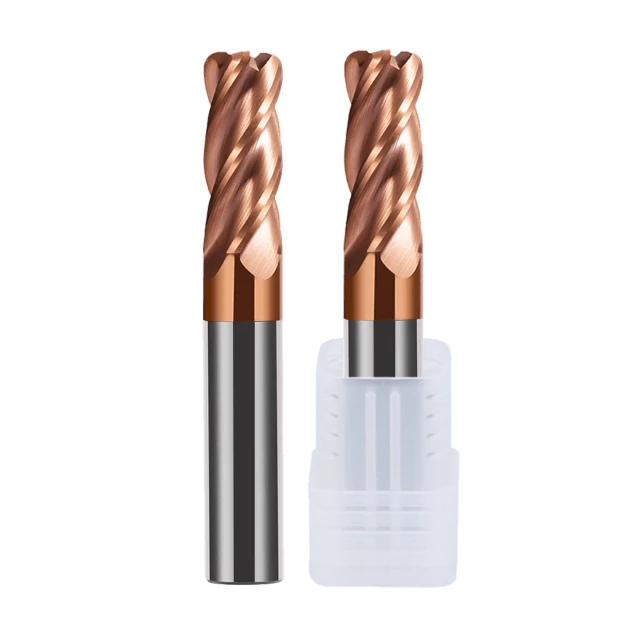
Last week, a German mold shop contacted us about an issue machining HRC62 SKD11 steel cavity pockets on a 5-axis mill. Whenever they bumped the spindle speed, the tool produced a high-pitched squeal, followed instantly by micro-chipping along the cutting edge. Their lead engineer emailed us: “Your carbide substrate and coating are solid, so why does tool life jump around so much when we’re running your recommended speeds and feeds?”
We’ve seen this exact scenario over a hundred times throughout our sixteen years in tool manufacturing and shop-floor troubleshooting. Most machinists and buyers evaluating end mill bits for hardened steel spend 90% of their time comparing carbide grades, grain sizes, and PVD coatings like AlTiN or nACo. Yet, they often overlook the most critical mechanical factor: the tool’s flute geometry.
In hard milling, flute geometry isn’t just a static channel for clearing chips; it’s a dynamic system balancing core thickness, helix angles, flute spacing, and gullet polish. The fight between tool rigidity and chip clearance, microsecond force spikes, and cutting-edge heat buildup all come down to micrometer-level flute details. As a china end mill bits for hardened steel supplier, our tear-downs of thousands of failed tools reveal a consistent pattern.
For a solid carbide end mill bit cutting materials over HRC50, nearly 70% of early tool failures and chatter issues stem from a mismatch between flute design and real-world cutting conditions. When you’re milling materials past HRC60, have you ever had a carbide flat end mill bits setup fail from sudden edge chipping after just a few minutes, even with ultra-conservative light cuts?
Why do traditional constant-pitch/constant-spacing end mills inevitably suffer catastrophic failure when machining hardened steel?
To guys new to hard milling, tool failure usually gets blamed on excessive RPM or overly aggressive feed rates. But based on our sixteen years of CNC grinding experience, running a standard, equal-spaced flat end mill on hardened material is doomed from the start. When cutting edges are spaced at equal angles, high-speed rotation generates a fixed impact frequency every time a tooth enters and exits the workpiece, triggering severe resonance across the spindle, fixture, and part.
When machining soft steels or aluminum, plastic deformation in the material absorbs part of that impact force. Hardened steel offers zero physical cushioning, forcing those violent cutting forces to bounce straight back into the tool tip. Traditional symmetrical end mill bits for hardened steel crash into these high-frequency impacts head-on. The resulting resonance escalates exponentially, causing rapid fatigue, heavy edge chipping, or total tool breakage within seconds.
Insights from real-world customer complaints: How chatter destroys a solid carbide end mill in seconds
A North American automotive mold shop reached out with an urgent issue: their standard four-flute solid carbide end mill bit kept chipping along the side edges after less than eight minutes while clearing HRC58 mold steel cavities. We pulled their machining footage and spindle load graphs. The tool cut cleanly for the first two minutes, but as soon as the cut transitioned into an interrupted shoulder, the smooth hum turned into a sharp shriek.
That shriek is the classic signature of regenerative chatter. Once chatter starts, the microscopic wave pattern left on the wall acts as an impact trigger for the following tooth, creating a destructive feedback loop. In hard milling, chatter means your cutting edge is hammering the workpiece thousands of times per second instead of shearing clean chips. The coating strips off almost instantly, and the carbide substrate shatters like glass from structural overload rather than normal wear.
A rule derived from 16 years of practical machining: The physical tug-of-war between cutting forces and chip evacuation space when material hardness exceeds HRC50
After analyzing thousands of test runs in our shop, we found a clear rule of thumb: once material hardness crosses HRC50, your core engineering problem shifts overnight from chip evacuation to tool rigidity. Standard milling cutters use deep chip gullets to throw out big chips during high-feed cuts, but that open space eats away at the tool’s core diameter. Under heavy loads in hard steel, a small core causes micro-deflection, making the tool bend and vibrate under light cuts.
However, if you max out tool rigidity with a beefy core, you severely choke your chip space. Even though chips from hard milling are thin, powdery C-shapes, deep slots and heavy radial engagement still demand smooth chip travel. Without a refined flute transition, hot chips pack tight inside the gullets, causing secondary cutting and skyrocketing cutting temperatures. Choosing effective hardened steel end mill bits comes down to finding that tight sweet spot between web stiffness and low chip-flow resistance.
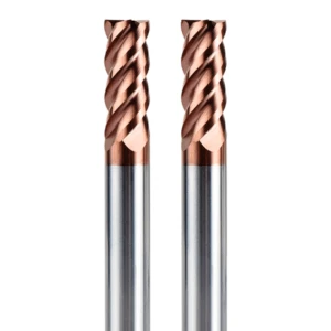
The Key to Overcoming Resonance: Practical Application of Unequal Indexing and Variable Helix Angles in Hardened Steel End Mill Bits
Once you fix symmetrical spacing issues, the next big step in custom geometry is breaking axial and radial symmetry. Machinists seeing asymmetrical end mills for the first time often ask why the teeth look unevenly spaced. In reality, that uneven design is our best defense against peak cutting force spikes in hard milling. By offsetting tooth positions, we break up the timing of each impact and scatter energy that would otherwise build into destructive chatter.
In actual production runs, the benefits of this design show up immediately on the shop floor. When milling HRC55 injection mold steel, swapping out a standard four-flute end mill for an asymmetrical design dropped spindle vibration by over 60%. Instead of hurting feed rates, this offset geometry let our hardened steel end mill bits run smoothly at higher RPMs, completely eliminating the annoying “orange-peel” chatter marks on finished wall surfaces.
How Unequal Indexing Breaks Phase Overlap in the Cutting Cycle
If you zoom in on hard milling at the microsecond level, every tooth impact sends a shockwave through the tool body. Symmetrical tools fire these shockwaves at a fixed frequency—like soldiers marching in step across a bridge—which triggers harmonic resonance. Unequal indexing breaks this cycle by offsetting the radial pitch angles slightly (typically between 88° and 92°). Before the vibration wave from one tooth can build up, the next offset tooth enters the cut and disrupts the harmonic wave entirely.
This asymmetrical layout proved its worth when we engineered custom solid carbide end mill bit options for a European precision manufacturer. When cutting deep slots in hard materials with heavy interrupted cuts, unequal flute indexing disrupted force peaks and smoothed out cutting resistance over time. This design reduced peak impact loads on the delicate tool tips during entry and stabilized the entire setup at elevated surface speeds.
Variable Helix Design: Reducing Lateral Cutting Forces While Maintaining Bottom-Edge Rigidity
Along with radial offsets, varying the axial helix angle plays a major role in killing vibration. Standard fixed helix angles (like a constant 35° or 45°) apply force in one uniform direction along the entire fluted length, which often pulls the tool and causes spindle axial runout. A variable helix design—like transitioning from 35° at the corner radius up to 38° higher up the flute—distributes cutting forces continuously along the tool axis, breaking axial resonance frequencies.
However, grinding these carbide flat end mill bits requires a careful balance. While a higher helix angle pulls chips out fast and lowers radial deflection, an overly aggressive angle weakens the tool corner where the end and side teeth meet. Our go-to setup uses a conservative helix angle near the bottom corner to absorb heavy entry shocks, combined with a steeper angle higher up the flute to clear chips fast, giving you maximum rigidity with minimal vibration.
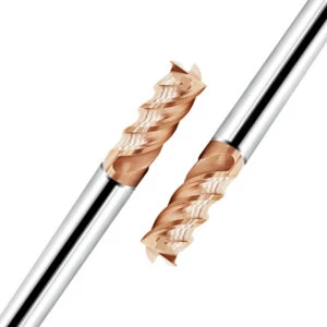
Pitfalls in Selecting Flute Count: 4, 5, or 6 Flutes for HRC65 End Mills?
When tackling extreme hard milling, machinists often make the mistake of blindly choosing tools with higher flute counts. The logic seems sound: more flutes mean more cutting edges in the cut, which should boost feed rates and surface finish. However, tool physics isn’t simple addition; adding flutes steals vital chip clearance room. Applied without considering radial engagement, high flute counts become the primary driver of tool failure.
Based on our 16 years of CNC grinding and setup experience, selecting flute count is a constant trade-off between web rigidity and chip pocket volume. We match flute count to your radial depth of cut and engagement angle. High flute counts excel in light-engagement finishing, but using them for heavy semi-finishing or deep slotting traps chips and snaps edges. When choosing HRC65 end mill bits, you must pick the right tool for the specific machining stage rather than assuming more flutes are always better.
4 Flutes vs 6 Flutes: Balancing Cutting Parameters and Chip Evacuation in Slotting and Side Milling of HRC50–HRC65 Mold Steels
In the HRC50–HRC65 range, 4-flute and 6-flute options are the two designs we compare most often on the shop floor. For full-slotting where tool engagement reaches 180 degrees, we strongly recommend a 4-flute setup. Chips generate fast in slotting and need deep gullets to curl and clear out. If you force a 6-flute tool into a full slot, the shallow gullets pack with debris, causing spindle load and heat to skyrocket.
Conversely, for high-speed side milling or trochoidal paths with light radial engagement, 6-flute or 8-flute cutters are absolute workhorses. Since radial depth of cut (ae) is only 5% to 10% of tool diameter, chips are paper-thin and clearance isn’t a bottleneck. Running 6-flute carbide flat end mill bits in these setups lets you boost table feeds by over 50% while lowering per-tooth load, delivering a mirror finish with maximum core stiffness.
Why Blindly Pursuing Higher Flute Counts Leads to Heat Buildup: Assessing Flute Valley Depth via Chip Color During On-Site Setup
Heat management is everything in hard milling. Because heat cannot easily escape into hardened workpieces, most thermal energy concentrates right at the cutting edge and chip interface. High-flute tools have shallow chip valleys, causing heavy friction as chips slide along the flute walls. If chips get trapped, this secondary friction cooks the tool, annealing the edge and triggering rapid breakdown.
When helping shops debug setups, we always diagnose performance by checking chip color and shape. During dry air-blast cuts, chips with a uniform pale purple or dark blue hue and neat C-shapes show that flute depth matches your parameters and heat is flying off with the chip. But if chips look dull black or ground into powder, your flutes are clogging. In these cases, switching to end mill bits for hardened steel with deeper chip valleys extends tool life far better than just dropping your SFM.
Micro-Geometric Design of the Cutting Edge: The “Invisible Metric” Determining the Lifespan of End Mill Bits for Hardened Steel
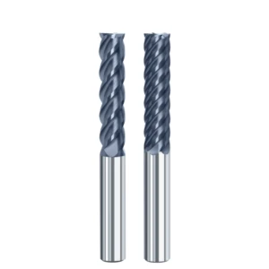
In tool manufacturing, machinists often assume that razor-sharp edges and mirror-smooth flutes automatically equal top performance. But in our 16 years of edge preparation research, we’ve found that tool life on hard steel depends on micro-features invisible to the naked eye. Above HRC50, macroscopic flute design only sets the baseline for chatter control; micro-edge prep dictates when and where microscopic stress cracks form.
We once ran a side-by-side test with two end mills using identical carbide substrates, coatings, and overall dimensions, varying only the micro-edge prep. The tool life gap on HRC60 mold steel was over 300%. For high-performance end mill bits for hardened steel, micro-geometry—like edge honing radii, micro-chamfers, and primary relief angles—is the real trade secret behind industrial-grade tool life.
Edge Honing (Edge Preparation) and Negative Rake Angles: Why Excessively Sharp Edges Fail Faster When Machining Hard Steel?
Razor-sharp edges work great on soft aluminum to prevent built-up edge, but they are disastrous on hardened steel. When slammed against high-tensile hardened surfaces, an un-honed edge cannot handle the massive normal forces. Stress spikes right at the razor tip, causing immediate micro-chipping. This is why novice programmers often complain that brand-new end mills chip the second they enter the cut.
To stop this, we apply precise edge prep using nylon radial brushes and micro-abrasives. We hone a uniform K-factor radius or negative micro-chamfer along the edge line. Combining a subtle negative rake with a rounded edge shifts cutting forces away from the delicate tip and spreads them across the hone land. When running HRC65 end mill bits in hard finishing, this reinforced edge prevents micro-chipping and maintains its form under intense cutting heat.
The Trade-off Between Core Thickness and Relief Angle: Balancing Tool Rigidity and Cutting Resistance
Balancing core thickness ratios against primary relief angles is a micro-meter battle we refine on our CNC grinders every day. Core diameter determines a tool’s section modulus and bending strength. By opening up the core ratio on our hard-milling cutters from 60% to 70%, we eliminate tool deflection in deep cuts. However, every micron added to the core squeezes the clearance space available behind the edge.
If your relief angle is too steep, the carbide substrate underneath lacks support and chips under load; if it’s too flat, the flank rubs hard against the cut wall, creating extreme friction and work hardening. When grinding a solid carbide end mill bit for custom jobs, we use a compound dual-relief geometry. A tight primary relief right behind the edge gives max substrate support, backed immediately by a steeper secondary drop-off to clear the cut wall and keep cutting forces low.

As a Chinese Manufacturer of End Mills for Hardened Steel, Here Is How We Help Clients Reduce Cost-per-Part Through Optimized Flute Geometry
When talking with overseas clients, factory owners and buyers always ask the same question: how do we lower cost-per-part without sacrificing quality? The knee-jerk reaction is often searching for cheaper cutters. But throughout our 16 years of grinding and shop-floor experience, we’ve learned that cutting unit prices is a trap; those small upfront savings get eaten up by downtime, scrap, and tool changes. Real cost savings come from boosting tool durability through smarter flute geometry.
As a china end mill bits for hardened steel supplier serving global B2B clients, we know how much flute design impacts your bottom line. Matching geometry precisely to your workpiece material increases tool removal volume while lowering cutting forces and spindle load. Refining flute precision at the grinding machine isn’t just about making better tools; it’s about helping shops hit the perfect balance between cycle time and overall tooling costs.
Lessons Learned: Common Flaws in “Pseudo-Hardened Steel Tools” Regarding 5-Axis Grinding and Flute Design
When dissecting failed tools for overseas shops, we constantly find cutters labeled “for hard milling” that perform horribly. Most are just cheap general-purpose end mills sprayed with shiny PVD coatings and re-branded. Their fatal flaw is poor 5-axis grinding execution—operators push aggressive grinding wheel feeds on Rollomatic or Anca machines to hit production volume, leaving heavy wheel marks and stress points in the flute valley.
While these tools pass on soft steel, they fail instantly above HRC50. Without proper flute polishing, those grinding wheel marks create friction that traps hot micro-chips inside the flutes. Plus, uneven core runout forces individual teeth to absorb massive load spikes. When sourcing end mill bits for hardened steel, buyers who focus solely on specs and coatings fall right into this trap of premature tool failure caused by poor flute grinding.
Field Case Study: How a German Mold Manufacturer Increased Tool Life by 40% by Adjusting Flute Polish and Geometry
A German automotive stamping mold shop contacted us about an issue machining HRC60 Cr12MoV steel with a premium Western brand. Their side edges were wearing out in under 12 hours of runtime. After analyzing their programming and spindle load data, our engineers pinpointed the issue: extreme friction during deep slotting. Although the carbide substrate was hard enough, the stock flute finish created severe secondary heat as powdery chips dragged along the gullets.
We customized a batch of end mill bits for hardened steel tailored to their exact cut strategy. We upgraded the flutes to a mirror polish and added a subtle 2° variable helix to smooth out force spikes heading toward the spindle. Without dropping cutting speeds, the polished flutes stopped heat buildup and slowed flank wear dramatically, extending tool life by 40% and saving the shop tens of thousands of euros in tooling costs.
A Technical Checklist for Selecting a High-Quality Supplier of End Mill Bits for Hardened Steel
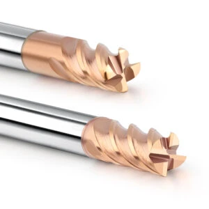
Translating flute geometry, core ratios, and micro-edge prep into actual shop results requires a strict supplier vetting strategy. Over 16 years in tool manufacturing, we’ve learned that choosing a grinding partner goes far beyond unit pricing on a quote. Machining hard materials demands extreme batch-to-batch consistency; a geometric drift of just a few microns leads to wildly unpredictable tool life on parts over HRC60.
If you want a stable supply chain, look past factory square footage or glossy marketing and inspect how well a vendor controls micro-flute geometry. From variable helix angles to edge honing, the true drivers of part yield are micron-level tolerances across thousands of tools. Partnering with a technically capable end mill bits for hardened steel supplier gives your shop a repeatable cutting process you can rely on every shift.
Look Beyond Price: Evaluating Flute Grinding Precision and Consistency on 5-Axis Machines
When auditing a tool factory, focus on their CNC grinding department and quality control standards. High-end 5-axis grinders from Rollomatic or Anca are essential for complex flute geometry, but great machines don’t automatically guarantee great tools. Ask about their wheel mesh grit, dressing intervals, and flute polishing routines. If a shop pushes grinder feeds to rush orders, microscopic drag lines stay behind at the flute root, creating prime stress fracture points under heavy cutting loads.
If you’re dealing with erratic tool life or sudden tool breakage on the floor, ask your vendor for a 3D flute profile inspection report. Top manufacturers of a solid carbide end mill bit use optical measuring systems to monitor unequal indexing angles and variable helix gradient curves on every batch. Achieving ultimate grinding consistency is the only way to guarantee every single cutter hits the exact same target runtime on your machines.
Key Geometric Parameters and Runout Data to Verify During Tool Testing
Before running sample tools on your CNC mill, pull them aside and measure three core geometric metrics: edge hone uniformity, relief-angle-to-core ratio, and flute surface finish (aiming for a mirror polish). These three micro-features dictate whether a tool can balance edge strength with heat control when cutting HRC50–HRC65 hardened steels.
Most importantly, never skip checking total radial runout. Even with perfect geometry, clamping runout over 0.005mm (0.0002″) overloads individual teeth and causes premature chipping. If you’re struggling with tough hard-milling jobs or tight corners in SKD11, H13, or powder metallurgy steels, feel free to reach out with your drawings and cut data. We’ll help you dial in the ideal flute geometry and prove out the efficiency gains in your real-world cutting environment.






