


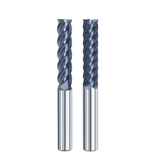
A mold shop supervisor from Bavaria, Germany, recently sent our technical team a machining video along with photos of several destroyed tools. While using a 5-axis machining center to rough-cut mold steel (1.2379/D2) at HRC58, they experienced severe built-up edge (BUE) formation within ten minutes of slot milling, immediately followed by edge chipping. After reviewing their CAM strategy, we spotted a classic mistake: they were using a 6-flute hrc65 solid carbide square end mill for a heavy slotting cut.
Scenarios involving tool breakage, chatter, or poor surface finishes due to improper flute count selection recur weekly in the shop floors we support across Europe and America. When machining stainless steel, titanium, or hardened steels, engineers often assume that more flutes automatically mean higher rigidity and efficiency. However, in the dynamic balance between cutting forces, chip pockets, and core ratios, flute count determines both heat accumulation and the actual service life of your end mill bits for metal.
As a team dedicated to the long-term R&D and manufacturing of carbide end mill bits, we test tons of stock in our CNC facility while helping overseas clients optimize complex components. From tool geometry design to analyzing cutting force behavior during high-speed machining (HSM), selecting your flute count is never simple math. It is a precise balancing act between tool rigidity, chip evacuation, and cutting force distribution.
Do you have any hrc65 end mill bits in your shop—featuring premium substrates and coatings—that consistently fail to meet their expected service life?

The Trade-off Between Flute Count, Chip Evacuation, and Rigidity: Fundamental Physical Principles Observed in CNC Machining
When fine-tuning machining strategies on the shop floor, we remind clients that selecting end mill bits for metal involves much more than reviewing outer diameter specifications. Every addition of a flute fundamentally redistributes the internal geometric space of the tool body. In tool manufacturing, our primary challenge is balancing chip evacuation channels against core strength within a fixed circular cross-section.
When encountering vibration, shop engineers often instinctively switch to thicker, more rigid cutters. However, from the perspective of cutting mechanics and thermodynamics, rigidity and chip clearance represent an irreconcilable conflict. Blindly sacrificing chip pocket volume for raw strength traps hot swarf inside the cut, causing thermal extrusion that destroys the microscopic cutting edge instantly.
Balancing Chip Pocket Space and Tool Core Diameter in Metal End Mill Design
When engineering high-performance metal end mill bits, the ratio between core diameter and chip pocket depth forms the soul of the tool’s geometry. Generally, the core diameter dictates bending resistance; expanding it by 10% significantly boosts strength against lateral cutting forces. However, since total cross-sectional area is fixed, a larger core inevitably shrinks chip pockets, directly altering chip curling and evacuation paths.
In our internal cutting tests, large chip pockets proved far more critical than raw rigidity when milling aluminum or mild steel. Conversely, when side-milling hardened steels, the rigidity of a thick core effectively suppresses edge micro-chipping. Experienced engineers learn to strike a rational balance between chip evacuation efficiency and structural rigidity based on specific workpiece conditions.
Why Blindly Increasing Flute Count Leads to BUE and Tool Breakage in Deep Cavities
When analyzing tool failures for overseas clients, we find that most BUE and breakage incidents during deep-cavity milling stem from choosing too many flutes on a carbide end mill bits design. When machining depths exceed twice the tool diameter, chips must travel much further to exit. Using 5- or 6-flute cutters in these deep pockets severely restricts flute volume, compressing swarf before coolant or air blasts can clear it.
Intense friction inside these narrow flutes generates extreme heat, causing chips to soften and weld onto the cutting edge to form BUE. Once BUE blocks the remaining flute space, cutting forces spike exponentially within milliseconds, leading to catastrophic brittle fracture under high spindle speeds. In deep-cavity milling, we consistently advise lowering the flute count to give swarf an adequate escape route.
The True Impact of Flute Count on Feed per Tooth (fz) and Cutting Force Distribution
When setting CAM parameters, programmers often assume that more flutes allow for proportionally higher table feed rates. Theoretically, feed rate equals spindle speed times flute count times feed per tooth (Vf = n*z *z). However, in practical metal cutting, adding teeth forces you to reduce actual chip thickness per tooth (fz) to avoid overloading the tool, shifting the action from efficient shearing to extrusive friction.
When feed per tooth drops below the cutting edge’s microscopic hone radius, the tool stops shearing metal cleanly and begins rubbing the workpiece surface violently. Our force-dynamometer data shows that this high-frequency friction spikes cutting zone temperatures and generates excessive radial forces. Understanding how tooth count shifts vector forces helps you boost feed rates without driving cutting edges into destructive frictional wear.
From 2 Flutes to 6 Flutes: Practical Strategies for Matching Flute Counts to Metal Materials
When providing custom tooling services to shops across North America and Europe, we often see clients attempting to use a single flute configuration for every job. While this might simplify inventory management, it comes at a heavy cost in machining efficiency and part economics. Metals differ vastly in plasticity, thermal conductivity, and chip formation, making proper flute selection critical for end mill bits for metal.
From ductile aluminum prone to chip welding to tough hardened steels, changing flute count fundamentally redefines the thermodynamic limits of the cut. After logging tens of thousands of test cuts in our laboratory, we know that matching flute count to a material’s chip formation mechanism unlocks full spindle power and process stability. Below are our field-proven strategies across typical metal machining scenarios.
Machining Aluminum Alloys: Why 2-Flute and 3-Flute End Mills Remain Kings of Chip Evacuation
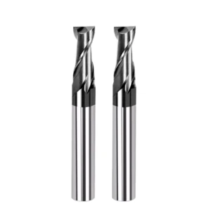
When machining 6061 or 7075 aluminum, the main threat is not tool breakage, but severe chip welding at high temperatures. Aluminum produces voluminous, sticky swarf that will instantly clog narrow gullets if not ejected in milliseconds. When manufacturing metal end mill bits for aluminum, we rely on 2-flute or 3-flute geometry to provide expansive, open parabolic chip pockets.
In high-speed milling (HSM), 3-flute end mills offer a distinct advantage over 2-flute cutters by adding an extra point of support. This extra contact balances centrifugal forces and reduces cutting pulsations during high-RPM passes. For deep slotting or heavy pocketing in aluminum, 2- and 3-flute tools remain unrivaled, as 4-flute designs often cause catastrophic tool melting from trapped swarf.
Machining Stainless Steel: Balancing Versatility and BUE Prevention with 4-Flute Carbide End Mills
Difficult metals like 316L stainless steel or Inconel 718 present a dual challenge: poor thermal conductivity and rapid work hardening. For clients cutting aerospace components, our primary recommendation for carbide end mill bits remains a 4-flute design. A 4-flute tool strikes an ideal balance, offering strong core rigidity against high forces while preserving enough flute volume for curled stainless swarf.
From a thermal perspective, a 4-flute tool maintains a stable engagement cycle, giving each cutting edge a microsecond cooling gap between revolutions. Fewer than four flutes overloads individual teeth and accelerates work hardening, while more than four flutes restricts chip space and causes secondary chip rubbing. For mixed slotting and side-milling in stainless steel, 4-flute tools deliver exceptional versatility.
Side Milling Hardened Steel (HRC50–65): Surface Finish Performance of Multi-Flute HRC65 End Mills
When steels are quenched above HRC50, chip formation shifts from continuous plastic ribbons to fine, powdery debris. Because chip volume drops drastically, pocket clearance becomes secondary to core rigidity and deflection resistance. In testing hrc65 end mill bits for mold finishing, 5- and 6-flute geometries consistently outperform standard tools during light-radial, deep-axial cuts (HEM paths).
Multi-flute geometry vastly increases core strength, virtually eliminating tool deflection during high-speed finishing. Furthermore, more flutes yield frequent, micro-depth cuts per revolution, distributing force evenly and suppressing chatter. When finishing hardened molds, 5- or 6-flute cutters allow tiny feed increments that erase tool marks and produce mirror finishes, cutting manual polishing costs.
Flute Count Selection and Corner-Clearing Performance of HRC65 Solid Carbide Square End Mills in Mold Machining
In hardened mold production, heat-treated steel places extreme stress on the sharp corners of square end mills. When assisting clients with SKD11, DC53, or NAK80 tool paths, we frequently catch misunderstandings regarding hrc65 solid carbide square end mill selection. Milling 90° sidewalls subjects the tool tip radius to heavy stress, where flute count directly dictates force distribution and dynamic stability.
High-hardness mold machining relies on low radial depths, high spindle speeds, and aggressive feeds—a stark contrast to traditional heavy-cut roughing. When engineering square end mills for HRC65 steel, we optimize substrate toughness, PVD thermal barriers, and flute counts matched to the corner arc of engagement. Balancing tooth count against radial engagement ensures long tool life while preserving precise right-angle geometry.
Comparing 4-Flute and 6-Flute HRC65 Solid Carbide Square End Mills in Hardened Steel
There is a clear performance divide between 4-flute and 6-flute cutters when roughing and side-milling hardened steels (HRC55–65). Dynamometer testing shows that during trochoidal or light-radial side milling, a 6-flute hrc65 solid carbide square end mill spreads loads evenly across more teeth. This high-frequency, low-chip-load action reduces peak tooth impact, preventing tip micro-chipping while maintaining straight sidewalls.
However, the dynamic flips during full-slot roughing or heavy radial engagement. Thanks to larger chip channels and reduced radial force, 4-flute cutters offer superior stability against lateral spindle thrust. Using a 6-flute tool in heavy engagement causes radial forces to spike, triggering tool deflection and rapid tip wear, making 4-flute cutters best for roughing and 6-flute cutters ideal for finishing.
On-Site Solutions for Chatter on Right-Angle Mold Corners
During cavity corner milling, a tool transitions abruptly from a straight path into a tight corner, causing engagement angles to jump from 90° to 180°. When troubleshooting corner tool breakage, we find that multi-flute square cutters generate sudden force spikes in these turns. This shock triggers machine resonance, producing harsh chatter, surface vibration marks, or snapped tool tips.
To solve this on-site issue, we advise implementing CAM arc-based corner smoothing while adjusting physical tooling setups. We recommend stepping down slightly in tool diameter for multi-pass cornering or reducing RPM to clear the machine’s resonant frequency. Additionally, minimizing tool overhang and employing rigid shrink-fit holders are essential steps to suppress chatter under high corner loads.
Enhancing Vibration Resistance Through Unequal Pitch Geometry
When machining hard materials with standard equal-pitch cutters, identical time intervals between tooth impacts create periodic shocks that trigger severe resonance. To eliminate this issue at the geometric level, we build variable index (unequal pitch) and variable helix features into our hrc65 end mill bits. Breaking the symmetry of the cutting edges turns continuous harmonic impacts into non-periodic micro-vibrations.
This irregular tooth spacing disrupts the phase conditions required for resonance, actively dampening radial excitation forces. In customer side-milling tests on hardened mold bases, these anti-vibration tools ran smoothly with zero chatter, even with table feeds increased by 20% to 30%. For shops regularly milling deep cavities in hard metals, multi-flute tools with anti-vibration geometry offer an immediate boost to process reliability.

Common Machining Pitfalls in Western Workshops: Frequently Reported Errors in Selecting Tool Flute Counts
In over a decade of technical collaboration with North American and European workshops, we have seen frontline engineers fail to achieve expected efficiency despite using top-tier CNC machinery. Analyzing scrapped samples and field video reveals that most issues stem from misunderstanding flute selection logic rather than manufacturing defects. Because cutting mechanics vary drastically by tooth count, forcing a tool into an incompatible setup causes edge chipping and downtime.
We compiled these reported pitfalls to help you prevent costly selection mistakes during production planning and tool sourcing. Every choice on the shop floor requires balancing spindle power, chip evacuation resistance, and CAM toolpath strategy. Avoiding these subtle errors will significantly extend tool life while protecting your shop from unexpected part scrapping and scheduling delays.
Pitfall 1: Believing More Flutes Mean Better Durability during Heavy Slotting
When customers bring us shattered tooling, they often explain their logic as: “I picked more flutes and a thicker core so the cutter would last longer.” However, this approach backfires completely during 100% Ae slotting, where swarf has no lateral escape path. When using a 5- or 6-flute cutter, limited chip gullet volume clogs instantly, causing severe swarf recutting.
Intense chip compression inside narrow slots causes local temperatures to spike and cutting forces to surge, resulting in catastrophic tool breakage within seconds. When redesigning slotting processes, we advise clients to revert to 2-flute or 4-flute end mill bits for metal while increasing feed per tooth and air pressure. Providing adequate chip clearance builds far more process stability than blindly relying on core rigidity.
Pitfall 2: Stalling Low-Power Spindles with Multi-Flute Carbide End Mills
Another frequent mistake in small-to-medium shops is running multi-flute tools on low-power BT30 or light BT40 machines. Attracted by high table feed recommendations, operators load multi-flute cutters without realizing that engaging more teeth simultaneously increases required real-time torque exponentially.
If spindle torque cannot handle the high cutting resistance of multi-flute carbide end mill bits, spindle RPM drops instantly upon entry, stalling the machine. This RPM drop surges the effective feed per tooth ($f_z$) far beyond the edge’s yield limit, causing total tooth shearing. When evaluating job feasibility, always match flute counts to your machine’s torque curve rather than catalog feed rate limits.
Pitfall 3: Ignoring How CAM Toolpaths Dictate Flute Selection for HRC65 End Mills
While High-Efficiency Milling (HEM/trochoidal) has become standard for hard materials, many engineers fail to upgrade their flute selection alongside their CAM strategies. Traditional heavy engagement paths required 4-flute tools to balance chip clearance and radial forces. However, modern trochoidal paths use narrow radial widths (10%–15% Ae), meaning standard 4-flute hrc65 end mill bits waste significant machine capacity.
Because light radial engagement prevents chip packing and dissipates heat quickly, trochoidal paths create the ideal environment for 5- or 6-flute cutters. These multi-flute geometries maintain high-frequency engagement, pushing feed rates to maximum machine limits. Conversely, using trochoidal multi-flute tools on high-engagement traditional paths causes rapid overheating and premature wear.
How to Select or Customize Optimal Flute Counts from a China End Mill Bits for Metal Factory
Selecting tooth counts is never an isolated decision; it requires evaluating your entire cutting system. As an engineering team from a direct china end mill bits for metal factory, our primary role is helping shop managers analyze these dynamic variables. Partnering directly with a manufacturer lets you leverage specialized R&D and flexible grinding to match flute counts, core ratios, and geometries to your exact needs.
Off-the-shelf tools often force compromises during complex or high-volume production runs. If your goal is reducing per-part costs and maximizing spindle output, direct communication with factory tool engineers to develop custom tools is your most cost-effective path. Below is our standard workflow—from initial parameter review to shop-floor validation—to guide your future tooling procurement.
Key Cutting Parameters to Provide to Factory Engineers
When contacting a china end mill bits for metal factory for technical sourcing, sharing precise data significantly improves trial success. Requesting quotes based only on outer diameter and flute length is insufficient for engineering proper geometry. To help us engineer the right flute count and core ratio, always provide workpiece hardness, milling strategy (slotting vs. HEM), spindle torque curves, holder types, and coolant pressure.
If you experience BUE breakage during slotting or corner chatter during side milling, send our engineering team failure photos along with your axial (Ap) and radial (Ae) parameters. As tool manufacturers, we reverse-calculate actual cutting forces and chip volumes from your data, allowing us to specify the ideal flute configuration for your metal end mill bits.
How Manufacturers Customize Carbide End Mills via Flute, Helix, and Core Adjustments
Customizing a high-performance tool involves far more than altering tooth numbers in a grinding program; it requires re-engineering the cutter’s structural mechanics. When designing custom carbide end mill bits, our engineers balance flute count, helix angle, and core diameter ratios together. For instance, when adding flutes for finishing efficiency, we often increase helix angles from 35° to 45° to smooth force transitions and compensate for smaller gullets.
If you machine aerospace stainless or hard mold steels where general-purpose tools chatter, consider requesting a multi-flute design with unequal pitch and variable helix angles. Controlling individual tooth spacing on 5-axis CNC grinders breaks harmonic impact cycles, allowing custom multi-flute tools to maintain high rigidity while suppressing chatter. Re-engineering basic tool geometry unlocks the full capabilities of your CNC machinery.
From Sample Testing to Bulk Procurement: Verifying Tool Life on the Shop Floor
No matter how sound theoretical calculations appear, cutting performance must be validated amid flying chips. In our test facility and client shops, we follow a strict protocol for tool life testing. When evaluating sample end mill bits for metal, we look beyond catastrophic breakage by using optical microscopes to monitor flank wear (VB) at 10-, 30-, and 60-minute intervals while recording sidewall surface roughness (Ra).
When testing new supplier samples, establish a baseline benchmarking log: keep machine speed, feed rates, and coolant strictly constant while measuring edge wear against removed metal volume. Analyzing quantified wear curves reveals which flute configuration provides the lowest cost per cutting edge and the most consistent quality for your production line.






