Last week, we held an urgent late-night video call with a long-standing aerospace client in Germany. They were using our HRC65 thread mills to machine a batch of heat-treated, ultra-high-strength alloy steel with UNC specifications. The results on the shop floor were disastrous. While the tools did not break, the “Go” thread gauge jammed after just two threads, while the “No-Go” gauge spun right in.
This is a classic failure scenario we encounter repeatedly in high-hardness steel milling projects. When using carbide thread mills on hardened steel exceeding HRC60, you are engaged in a micron-level battle of tool deflection and CNC compensation. Under these extreme cutting forces, a standard thread mill for steel easily deflects, leaving an imperceptible taper within the bore.
Many workshops default to standard single-form straight-entry programming or overlook the conversion ratio between tool center feed and peripheral feed when running UNC thread mills. This oversight results in incomplete thread profiles, torn threads, or out-of-tolerance pitch diameters. For deep holes or integrated chamfering, standard tools completely fail, forcing us to design custom thread mills with variable helix angles and reinforced cores to eliminate chatter.
“Go” gauge failures, torn teeth, and abnormal coating delamination cannot be solved by cold textbook theories. In real-world machining, cooling fluctuations, radial depth of cut (ae) tweaks, or a “roll-in” arc entry determine whether a $5,000 forging becomes a finished product or scrap metal. Do you often face those frustrating shop-floor scenarios where the “Go” gauge won’t fit, but adjusting the tool offset causes the “No-Go” gauge to fail instantly?

Go/No-Go Gauge Failures: The Primary Challenge When Using HRC65 Thread Mills on Hardened Steel
In hardened steel machining, Go/No-Go gauge failures are a constant, costly headache. When workpiece hardness hits HRC65, the material’s shear resistance rises exponentially, amplifying any minor process deviation. We frequently see machinists repeatedly tweaking tool radius compensation, only to find the “Go” gauge stuck at the hole entrance while the “No-Go” gauge unexpectedly slips right in.
As tool manufacturers, we know these inspection failures rarely stem from incorrect tool dimensions. Instead, they usually signal a critical lack of rigidity under extreme cutting loads. There is no “one-size-fits-all” formula here; solving this requires making pragmatic, real-world trade-offs between cutting efficiency, tool life, and micron-level precision.
Tool Deflection and Taper Issues: Balancing Rigidity and Cutting Forces for Carbide Thread Mills at High Hardness
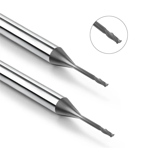
Aggressively cutting HRC65 steel creates immense repulsive forces between your tool and the workpiece. Although solid carbide thread mills offer exceptional hardness, their elastic modulus still has physical limits under high radial loads. Consequently, long tool overhangs cause slight deflection at the tool tip, creating a subtle taper where the thread depth at the bottom of the hole is insufficient.
Minimizing tool overhang is rarely an option when dealing with fixed, complex workpiece geometries. Our shop-floor experience shows the best solution lies in optimizing tool geometry by reducing the margin width and increasing the relief angle to lower cutting resistance. Additionally, your CNC program should utilize a helical retraction path, using a “pull-milling” strategy to leverage the machine spindle’s inherent rigidity.
Pitch Diameter Out-of-Tolerance: Overcoming Precision Bottlenecks with UNC Thread Mills via CNC Offset Fine-Tuning
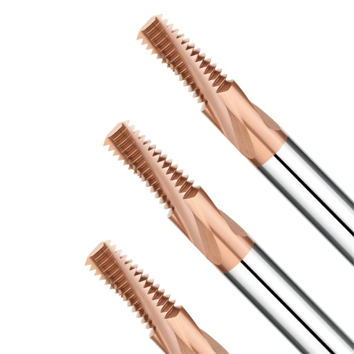
When machining Unified Coarse threads, the wide 60-degree profile angle causes the cutting contact area to expand rapidly as depth increases. Many engineers accustomed to standard carbon steel mistakenly apply large, single-pass radius compensation adjustments on their CNC controllers. However, when running unc thread mills in HRC65 steel, such crude adjustments trigger drastic fluctuations in spindle motor current, resulting in a wavy pitch diameter.
We highly recommend a multi-pass, incremental approach when adjusting the thread mid-diameter. Each modification to your tool wear offset (the D-value in G41) should not exceed 0.02 mm while closely monitoring the spindle load percentage. If you must excessively increase tool compensation just to get the “Go” gauge to pass, stop and inspect the pilot hole’s taper rather than blindly fighting the control panel.
Spring Back: “Go” Gauge Failure in High-Toughness Hardened Steel and the “Spring Pass” Strategy
Beyond tool deflection, the physical properties of specialized die steels present a tricky, invisible variable. Certain tool steels retain high elastic deformation tendencies even after being quenched to extreme hardness. When your thread mill for steel completes its programmed path, the metal undergoes a micro-recovery, springing back the instant the cutting edge moves away.
This physical “spring back” means the finished thread space is smaller than the path actually swept by the tool, causing the “Go” gauge to bind. To fix this, we always add a “Spring Pass”—a finishing cycle with zero radial infeed—after the standard machining loop. It relies solely on the tool’s residual rigidity to shave off that elastic material, ensuring the “Go” gauge passes smoothly without loosening the “No-Go” side.

Poor Surface Finish and Thread Damage: Practical Adjustments for Optimizing Thread Machining
On extremely hard metals, thread surface finish dictates fatigue life and assembly precision. Seeing torn flanks, burrs, or ragged profiles instead of mirror-like finishes means the thermo-mechanical balance in your cutting zone has collapsed. Many shops try to fix this by blindly raising spindle speeds, but on HRC65 steel, that backfires by generating localized friction heat and accelerating thermal damage.
Based on our extensive history handling precision export orders, fixing surface finish requires evaluating chip morphology forces. Hardened steel produces incredibly brittle, razor-sharp chips that cause immediate tearing if they get trapped and recut in a blind hole. We solve this by adjusting three interconnected variables: cutting direction, thermal shock control, and cutting-edge micro-geometry.
Choosing Between Up Milling and Climb Milling: Chip Evacuation Observations During Workshop Testing of Thread Mills for Steel
When programming internal threads in hardened alloys, your cutting direction dictates your chip evacuation success. In our shop tests, using a conventional thread mill for steel in conventional up-milling mode forced the cutting edge to transition from thin to thick. This rubbing action creates severe work hardening and hurls hot chips forward into the path of the tool, leading to chip recutting and micro-tearing.
Therefore, we recommend a climb-milling strategy for almost all high-hardness applications. Climb milling enters the metal thick-to-thin, producing a cleaner chip curl and evacuating debris backward into the open, completed thread space. Just ensure your CNC machine has minimal ball screw backlash, as older guideways can suffer from stick-slip chatter under climb-milling forces.
Avoiding Pitfalls in Cooling Strategies: Why Blindly Using Emulsion Coolant Causes Thermal Cracking in HRC65 Thread Mills
Many machinists see smoke in the cutting zone and instinctively flood the bore with water-soluble emulsion. However, when running hrc65 thread mills, this traditional practice is catastrophic for tool life. The extreme heat generated at the cutting edge followed by instant quenching during interrupted circular interpolation creates intense thermal shock, rapidly cracking the underlying substrate.
Our troubleshooting sessions across US workshops confirm that thermal micro-cracking destroys cutting edges within just a few thread pitches. For these extreme hardness levels, we highly advise dry cutting paired with high-pressure air blasts (above 6 bar) or MQL. This maintains a stable thermal environment and uses velocity to blast hot, hardened chips completely out of the hole.
Micro-chipping at the Cutting Edge: Analyzing Coating Delamination on High-Quality Carbide Thread Mills Under High Magnification
When thread finishes degrade without warning and the tool looks unbroken, the culprit hides at a microscopic scale. Under 100x magnification on used carbide thread mills, we frequently see patchy nano-coating delamination or micro-scale chipping along the substrate edge. These microscopic jagged imperfections act like tiny saws, instantly scraping and destroying the workpiece thread crests.
This premature coating failure usually stems from an incorrect balance between edge sharpness and edge strength. Excessively sharp edges chip instantly under HRC65 impacts, while over-passivated edges generate friction heat that causes coating separation. We use a proprietary suspension polishing process to control this edge radius within a strict micron range, though you must still keep tool runout under 0.005 mm to prevent uneven tooth loading.
Damaged Threads and Incomplete Profiles: Programming Corrections for Large-Pitch and UNC Thread Mills
Machining large-pitch threads frequently introduces severe profile distortion and torn flanks. A larger thread pitch requires a deeper radial depth of cut and greater tool engagement, causing spindle torque requirements to surge exponentially. When shops encounter flattened crests on coarse threads, they often blame tool manufacturing defects, but our team’s site audits prove the fault almost always lies in the CNC toolpath logic.
At extreme hardness thresholds, old programming habits must yield to physical force limitations. You cannot crush through large-pitch hard steel in a single interpolation pass without destroying the tool’s carbide microstructure. Eliminating torn profiles requires using your programming code to smooth out initial impact forces, step down radial engagements, and compensate for circular interpolation kinematics.
Toolpath Improvement: Abandoning Straight Radial Entry in Favor of Arc Entry (Roll-in Entry)
Plunging a tool straight along a radial line into hardened steel exposes the lead teeth to a violent impact. This sudden load spike is the leading cause of chipped leading edges on large-pitch unc thread mills. Straight radial entry punches the material, causing an instantaneous spindle current spike and leaving a localized chatter mark at the start point that ruins the rest of your circular trajectory.
To eliminate this, we guide our clients to rewrite their entry paths using a tangential arc entry, or “roll-in” method. This technique allows the tool to sweep into the cut along a smooth radius, letting chip thickness ramp up gradually from zero to your programmed feed rate. While manual G02/G03 programming for this entry takes a few extra calculations, it ensures stable tool loading and clean entry threads.
Multi-pass Milling: Recommended Radial Depth of Cut (ae) for High-Hardness Steel
Attempting a single-pass full-depth roughing cut in HRC60+ steel is a massive gamble with your tool budget. When running a standard thread mill for steel, excessive radial depth of cut (ae) generates side-pressures that physically deflect the cutter body. This deflection shows up as a tapered, out-of-spec thread form that is tight at the bottom and loose at the top, which can only be corrected by multi-pass strategies.
Our sixteen years of testing data on hard mold steels indicates that large-pitch threads require three to four radial passes. We typically configure the first roughing pass to remove 50% to 60% of the total thread depth, followed by a 30% second pass. We then allocate a final finishing pass strictly limited to 0.05 mm, which clears out material spring-back without exposing the tool to excessive lateral loading.
Incorrect Peripheral Feed Rate Calculation: Preventing Tool Center Overload in CNC Systems
This is a classic angular velocity pitfall that trips up over 90% of shop programmers and machine operators. Your CNC controller calculates internal circular interpolation based on the tool’s centerline trajectory, not its cutting edge periphery. If you input the raw peripheral feed rate directly from your tooling manual as the F-value, the machine tool center will travel far too fast, overloading your teeth.
When high-performance carbide thread mills snap immediately upon entering a hole, miscalculated centerline feed rates are almost always responsible. You must scale your program feed downward based on the ratio of the bore diameter to the tool diameter. The formula is straightforward: Center Feed = Contour Feed * (Bore Diameter – Tool Diameter) / Bore Diameter. Double-check your CAM software output against this calculation before hitting cycle start.
Unexpected Tool Breakage and Short Lifespan: Extreme Scheduling Strategies for Deep-Hole or Specialty Steel Machining
In precision mold and military-grade steel production, sudden tool breakage is an absolute nightmare. This is especially true when machining depths exceed twice the thread diameter (>2D). In these confined deep-holes, chips clog easily, causing frictional heat to spike. Many shops under tight deadlines blindly apply standard machining cycles, ignoring the stepped increase in cutting resistance.
This oversight results in tool lifespans falling short of expectations, alongside frequent tool jamming. Extending tool life requires more than lowering spindle speeds; it demands controlling pre-drill conditions and compensating for high length-to-diameter rigidity deficits. By distributing the physical load across preceding process steps, you can achieve stable batch production even under extreme scheduling demands.
Pushing Pre-drill Hole Dimensions to the Limit: Reducing Initial Cutting Loads for HRC65 Thread Mills
When tackling ultra-hard metals, technicians often strictly adhere to the lower limits of pre-drill hole charts. However, drilling the hole too small when running hrc65 thread mills forces the tool tip to remove excessive metal near the root during roughing. This initial cut overload acts as a hidden catalyst for premature thermal fatigue, leading to sudden, unannounced tool failure.
Provided final thread tolerances are met, we recommend adjusting your pre-drill hole size toward its upper allowable limit. Minor increases in the pilot hole diameter can reduce the metal volume removed during radial entry by nearly 20%. This fraction-of-a-millimeter optimization improves initial chip clearance and lowers spindle current, allowing high-hardness tools to engage the material smoothly.
Chatter Caused by Long Overhang: Switching to Custom Thread Mills with Adjusted Core Thickness and Variable Helix Angles
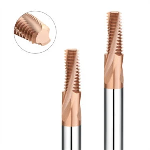
As thread depth increases, standard tool overhangs eventually cross a critical rigidity ratio, making chatter inevitable. This periodic vibration leaves unsightly ripples on the thread flanks and triggers rapid edge failure due to uneven impact loads. Many US machine centers struggle with this when length-to-diameter ratios exceed 3:1, as standard speed-reduction strategies sacrifice efficiency without eliminating resonance.
To tackle these deep-hole bottlenecks, we move away from standard catalogs and design custom thread mills tailored to the machine spindle’s dynamics. In these designs, we increase the tool’s core diameter at the base to enhance bending rigidity and incorporate variable helix angles. This geometry disrupts harmonic resonance during cutting, suppressing vibration and allowing you to maintain standard feed rates.
Zero-Scrap Breakage Prevention: Why Thread Mills for Steel Outperform Carbide Taps on Expensive Workpieces
When machining aerospace forgings worth thousands of dollars, a single broken tool can scrap the entire workpiece. Purchasing departments often question why we avoid using carbide taps to achieve faster cycle times. From a risk-mitigation perspective, if a tap snaps inside hardened steel due to torque overload, its rigid threads wedge firmly into the hole, making extraction nearly impossible without ruining the semi-finished part.
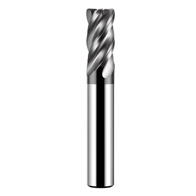
In contrast, choosing a high-quality thread mill for steel is the smartest route to a zero-scrap rate. Because the cutter’s diameter is smaller than the thread bore, there is ample geometric clearance for retraction. If a power outage or operator error causes a breakage, the broken carbide body will not wedge into the threads, allowing technicians to easily retrieve it with tweezers.
Solutions for Extreme, Non-Standard Conditions: When to Switch from Standard Tools to Custom Thread Mills
After addressing gauge failures, surface finish, and pitch compensation, we must confront a harsh shop reality. No matter how perfect a standard tooling catalog looks, it cannot cover every extreme geometry or specialty alloy. When dealing with thin walls, stepped obstructions, or weak fixtures, tweaking standard parameters wastes setup time. Compromising with standard tools often leads to a hidden loss of product quality control.
If you are currently evaluating orders for high-hardness, high-value components, we suggest shifting your focus from individual tool costs to overall cycle efficiency. Non-standard cutters are designed to directly match your machine’s ultimate rigidity by reconfiguring the tool body when standard options hit a dead end. The following two customization cases show how we solve these exact bottlenecks for our clients.
Aerospace-Grade Deep Holes and High Length-to-Diameter Ratios: A Case Study on Custom Carbide Thread Mills
An aerospace client needed to machine an internal thread with a 4D length-to-diameter ratio in HRC62 steel. They tried off-the-shelf carbide thread mills, but the long neck length required by standard tools caused a drastic drop in mid-section rigidity. This resulted in a 0.08 mm deflection at the bottom of the hole, making it impossible to pass the “Go” gauge despite extensive programming adjustments.
To break this rigidity bottleneck, we completely overhauled the tool’s structural proportions. For this custom design, we blended the shank-to-neck transition into a tapered, trapezoidal profile and applied an asymmetric negative chamfer to the relief angle. If you are struggling with deep-hole deflection, we invite you to share your specific operating conditions and drawings so we can optimize your tool’s core thickness.
Integrated Threading and Chamfering: Solving Burr and Efficiency Issues for European and American Clients in Mass Production
On high-volume production lines, Tier 1 suppliers enforce strict standards regarding total cycle times. Standard sequences involve drilling, chamfering, and then threading, but frequent tool changes consume costly non-cutting time. Furthermore, on HRC65 hardened steel, separate tools often leave microscopic burrs at the chamfer transition that compromise gauge fit. We frequently resolve this exact conflict when optimizing automotive lines.
For workstations where cycle time is critical, we routinely deploy integrated, multi-functional custom thread mills. By combining chamfering and threading edges onto different stepped sections of a single tool, it deburrs the hole entrance immediately upon completing its final interpolation pass. If you are facing production bottlenecks, share your material specifications and tooling list with us, and we can design an integrated solution.