


Last month, a long-term medical device client from the U.S. called our technical department. Their senior process supervisor was beyond frustrated. They were using high-end carbide tools designed for ceramics to machine high-purity alumina insulators. The problem? Every single part showed severe edge chipping at the tool exit point. Their scrap rate had skyrocketed past 35%.
This scenario is all too familiar to us. Over the past 15 years supporting North American and European shops, we have seen this crisis repeatedly. Many machinists try to apply metal-cutting logic to industrial ceramics. This is a mistake that leads to destroyed tools and binned parts. Ceramics have extreme hardness but near-zero fracture toughness. Conventional cutting logic doesn’t apply here. When a standard ceramic milling cutter hits fully sintered ceramic, it doesn’t “cut.” Instead, the edge dulls instantly and starts “pushing” the material. That violent impact is exactly what causes brittle fractures and massive chipping.
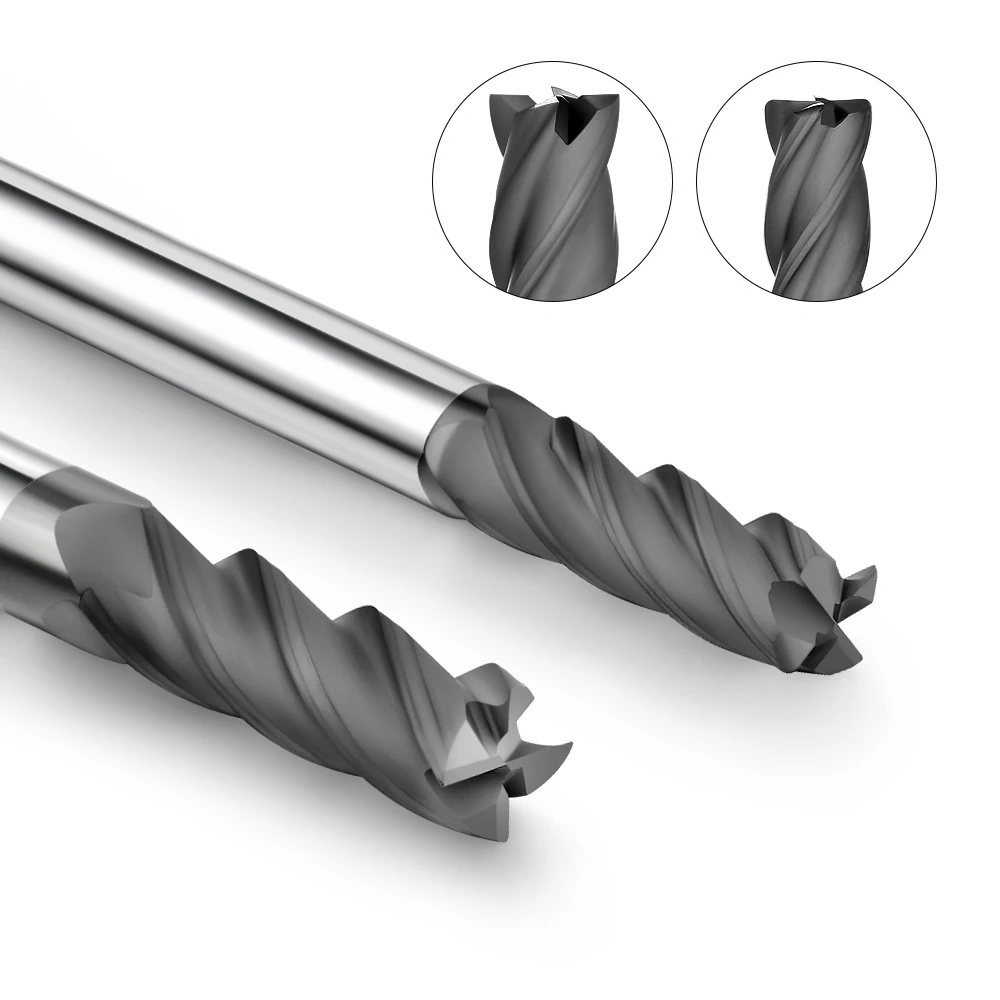
To stop edge chipping, you must upgrade to high-performance diamond end mills for ceramic. Only the extreme micro-hardness and low friction of CVD or PCD can keep a cutting edge sharp during these abrasive operations. In extreme cases—like machining Silicon Carbide (SiC) or ultra-thin 3D structures—we often design custom diamond milling cutters. By tweaking the helix angle, core rigidity, and flute geometry, we can redirect cutting stresses.
But be honest: is simply buying a high-quality diamond end mill enough? Why do some shops upgrade to the best tools and still see edges shatter within the first few minutes?
Why Do Traditional Carbide Tools for Ceramics So Frequently Lead to Edge Chipping?
In our shop, we have a joke: trying to mill sintered engineering ceramics with standard carbide is like trying to cut high-hardness glass with a plastic knife. In our early years, we spent many sleepless nights at the machine with our clients. We watched box after box of expensive solid carbide end mills grind down to blunt stumps in minutes. Then came that dreaded sound—the ceramic edge snapping off. It taught us a hard lesson. The “hard-on-hard” logic of metalworking fails completely against materials with zero capacity for plastic deformation.
When engineers see chipping, their first instinct is to kill the feed rate or drop the spindle speed. Often, this makes it worse. The root problem isn’t just the parameters; it is that carbide tools for ceramics cannot handle the intense abrasiveness. When the tool’s micro-hardness is too close to the ceramic’s hardness, wear accelerates exponentially. Once the tool loses its sharp geometry, the fragile equilibrium is shattered.
Rapid Wear of the Carbide Substrate and Surging Cutting Forces
Our real-time monitoring shows that flank wear on carbide starts the second the tool touches the ceramic. Without the protective lattice of a diamond coating, the ceramic surface acts like sandpaper. It ruthlessly strips away the cobalt binder holding the carbide together. As the binder erodes, tungsten particles detach, and the tool tip blunts—often too fast for the naked eye to see. Our sensor data shows that once flank wear (VB) hits a certain threshold, the radial cutting force surges instantaneously.
In metal, a surge in force might just mean a bad surface finish. In brittle ceramics, it’s a disaster. This surging force creates extreme tensile stress. When that stress exceeds the ceramic’s fracture toughness, cracks propagate uncontrollably along the grain boundaries. Usually, before the tool even reaches half its axial depth of cut (ap), the material fails. Instead of being turned into fine powder, it fractures and peels away in large chunks. This is the macroscopic chipping we all want to avoid.
The “Extrusion” Effect: Why Dulling Destroys Brittle Materials
Look at the cutting edge under a microscope. A brand-new cutter has an edge radius of only a few microns. At this stage, it can still “scrape” the ceramic. However, as the carbide wears, that sharp edge becomes a rounded surface. When the edge radius becomes larger than your feed per tooth (fz), the physics change. The tool stops shearing and starts “extruding”—plowing into the surface with high pressure.
This extrusion effect creates immense hydrostatic pressure ahead of the tool tip. In brittle materials, this “squeezing” causes severe subsurface damage and hidden micro-cracks. As ceramic milling cutters reach the exit edge of a part, there isn’t enough material volume left to support that load. The latent micro-cracks release instantly in the direction of the pressure. The result? The entire edge shatters the moment the tool exits.
The Tipping Point: When to Abandon Carbide for Post-Sintering Machining
We’ve helped dozens of precision shops in the U.S. and Europe run cost-benefit evaluations on this. If you are roughing ceramics in the “green state” (unfired) or semi-sintered stage, carbide tools for ceramics are actually very cost-effective. At that stage, the material feels like hard gypsum, and wear is manageable. But once the ceramic is fully sintered to its final density, the rules change.
Most of our Western clients use a strict quality standard: if an edge chip exceeds 0.05 mm (approx. .002″), the part is scrap. When milling sintered alumina or silicon nitride, a standard carbide tool usually can’t finish one single part before the edge quality fails. Between the machine downtime for tool changes and a scrap rate over 30%, your costs explode. This is the tipping point where smart supervisors switch to custom diamond milling cutters. Rational engineers know it’s cheaper to buy a harder tool than to keep throwing expensive ceramic substrates in the trash.
Why Do Traditional Carbide Tools for Ceramics Frequently Lead to Edge Chipping?
In our shop, we joke that milling sintered technical ceramics with standard carbide is like cutting high-hardness glass with a plastic knife. Early on, we spent countless sleepless nights with clients at their machines, watching expensive solid carbide end mills grind down to blunt stumps in minutes—followed by the dreaded sound of the ceramic edge snapping off. It taught us a hard lesson: the traditional “hard-on-hard” metalworking principles fail completely against materials with zero capacity for plastic deformation.
When engineers see chipping, their first instinct is to drop the feed rate or drop the spindle speed, but this often makes it worse. The root problem isn’t just the parameters; it is that standard carbide tools for ceramics cannot handle the intense abrasiveness of the material. When the tool’s micro-hardness is too close to the ceramic’s hardness, wear accelerates exponentially. Once the tool loses its sharp geometry, the fragile equilibrium is instantly shattered.
Rapid Wear of the Carbide Substrate and Surging Cutting Forces
Our real-time monitoring shows that flank wear on carbide starts the second the tool touches the ceramic. Without the protective lattice of a diamond coating, the ceramic surface acts like sandpaper, ruthlessly stripping away the cobalt binder holding the carbide together. As the binder erodes, tungsten particles detach, and the tool tip blunts too fast for the naked eye to see. Our sensor data shows that once flank wear (VB) hits a certain threshold, the radial cutting force surges instantaneously.
In metal, a surge in force might just mean a bad surface finish. In brittle ceramics, it is a total disaster. This surging force creates extreme tensile stress concentrations; when that stress exceeds the ceramic’s fracture toughness, cracks propagate uncontrollably along the grain boundaries. Usually, before the tool even reaches half its axial depth of cut (ap), the material fails. Instead of being turned into fine powder, it fractures and spalls off in large chunks.
The “Extrusion” Effect—Rather Than “Cutting”—Caused by Microscopic Edge Rounding
Look at the cutting edge under a microscope. A brand-new cutter has an edge radius of only a few microns, allowing it to “scrape” the ceramic. However, as the carbide wears, that sharp edge quickly degrades into a rounded surface. When the edge radius becomes larger than your feed per tooth (fz), the physics change completely. The tool stops shearing the material and starts “extruding”—plowing into the surface with immense physical pressure.
This extrusion effect creates high hydrostatic pressure ahead of the tool tip, triggering severe subsurface damage and hidden microcracks. As ceramic milling cutters reach the exit edge of a part, there isn’t enough material volume left to support that load. The latent microcracks release instantly in the direction of the pressure. The result is heartbreaking: the entire edge shatters the moment the tool exits the cut.
The Tipping Point: When Western Clients Abandon Standard Carbide Tools
If you are roughing ceramics in the “green state” (unfired) or semi-sintered stage, standard carbide tools are actually very cost-effective. At that stage, the material feels like hard gypsum, and tool wear remains manageable due to its high impact toughness. But once the ceramic undergoes high-temperature sintering to reach its final density and hardness, you hit the tipping point where carbide must be abandoned.
Most of our Western clients use a strict quality standard: if an edge chip exceeds 0.05 mm (approx. .002″), the part is scrap. When milling sintered alumina or silicon nitride, a standard carbide tool usually can’t finish half a part before the edge quality fails. Between the machine downtime for tool changes and a scrap rate over 30%, your costs explode. This is when smart supervisors switch to standard diamond coated cutting tools or custom diamond milling cutters to fix the issue at its root.
Optimizing CNC Process Parameters: Preventing Ceramic Milling Cutters from “Shattering” Edges
We frequently meet clients who bought the most expensive diamond tooling on the market, yet remain utterly baffled by persistent exit-edge chipping. When we walk up to their CNC machines, the first thing we check isn’t the tool, but the G-code program. Frankly speaking, many shops still rely on traditional metal-cutting logic, increasing spindle horsepower and driving the tool straight forward. Consequently, their ceramic milling cutters end up acting like hammers violently pounding and shattering perfectly good ceramic components.
Optimizing the cutting process for hard, brittle materials is a delicate balancing act of controlling cutting stress direction and magnitude. When machining technical ceramics with virtually zero ductility, every feed increment and exit angle dictates the propagation path of microscopic cracks. During on-site machine setup, we often transform edge quality simply by reconfiguring the toolpath, feed per tooth, and radial depth of cut. This is the practical, shop-floor experience we want to share with you today.
The Decisive Role of “Climb Milling” Strategies in Reducing Load at the Exit Edge
In conventional metalworking, up-milling is sometimes used to tackle the hard surface “crust” on castings, but we strongly advise against it when milling ceramics. With up-milling, the cutting edge initiates contact at zero chip thickness, and the cutting force reaches its absolute maximum precisely as the tool exits. For highly brittle ceramics, attempting to forcibly peel away from the exit edge while bearing the maximum cutting load triggers severe brittle fracture.
Conversely, the climb milling strategy—which we invariably recommend—exhibits precisely the opposite cutting-force characteristics. When a diamond end mill for ceramic engages the workpiece via climb milling, the chip thickness is at its maximum upon entry and tapers down to zero at exit. By the time the edge leaves the workpiece, both cutting force and heat have dissipated to extremely low levels. Simply switching the machining direction to climb milling in your CAM software can instantly slash your scrap rate by half.
Moving Beyond Textbooks: How We Precisely Calculate the Feed Per Tooth (fz)
Many operators new to ceramics rely on general-purpose handbooks or static formulas when setting the feed per tooth (fz). However, in a real workshop, textbook data can cause serious trouble because different ceramics have vastly different properties. High-purity alumina is inherently brittle, while silicon nitride possesses superior fracture toughness. If you blindly apply a high feed rate to alumina, the impact force will trigger macroscopic chipping; if you set it too low for silicon nitride, the edge will just rub and destroy your diamond end mills.
Based on our machine optimization experience, a rational feed per tooth must balance the material’s micro-toughness with the actual edge radius of the tool. When machining alumina, we restrict the feed per tooth to an extremely narrow window, using a microscopic “grinding” effect to shed the material as fine powder. For silicon nitride, we moderately increase the feed rate so the tool can truly “bite” into the material. This dynamic parameter setting is exactly how we help our B2B clients establish a competitive edge.
The “Small Radial Depth of Cut (ae)” Rule for Preventing Edge Chipping in Dynamic Milling
With modern High-Speed Machining (HSM) and advanced CAM algorithms, we increasingly encourage our clients to utilize dynamic or trochoidal milling toolpaths. In traditional full-slot milling, the radial depth of cut (ae) equals the tool diameter, meaning a 180-degree contact angle that traps immense internal stresses within the workpiece. Under a dynamic milling strategy, we strictly limit the radial depth of cut to between 5% and 10% of the tool diameter, enabling smooth material removal through shallow radial and deep axial passes.
The primary advantage of a reduced cutting width is that it drastically lowers the average chip thickness, minimizing the impact on the ceramic’s grain boundaries. Even when navigating tight corners, dynamic milling automatically adjusts the feed rate so the tool does not shatter the workpiece due to a sudden increase in contact angle. For ultra-thin walls or high-aspect-ratio components, we combine this shallow trochoidal toolpath with our custom diamond milling cutters to smoothly nibble the material away to a mirror finish.
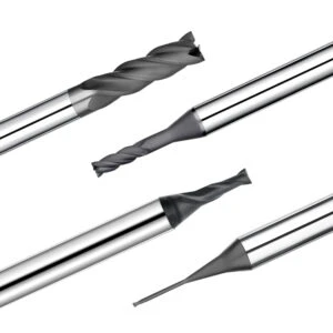
Extreme Chipping Issues That Standard Tools Can’t Solve? When to Consider Custom Diamond Milling Cutters
Off-the-shelf tools from major catalogs prioritize versatility over specificity, resulting in compromised cutting edges, helix angles, and overhang rigidity. When encountering deep slots, thin cantilevered features, or highly stress-sensitive ceramics, these standard tools quickly fail and leave parts riddled with chipped edges. When adjusting cutting parameters is no longer a viable compromise, you must step outside standard catalogs and commission custom diamond milling cutters.
By reconstructing the tool’s micro-geometry, we can redirect cutting forces toward the workpiece’s most structurally robust vectors. This tailored engineering approach effectively drives down the scrap rate on complex geometries where off-the-shelf alternatives fail. If you are currently stuck in the quagmire of persistent edge chipping on a challenging component, the following custom design strategies offer a proven path forward.
Tapered Neck and High Helix Angle Designs—Customized for Deep Cavity and Thin-Wall Machining
Standard long-neck end mills feature uniform-diameter necks with high aspect ratios that inevitably generate minute resonant vibrations at high spindle speeds. While these vibrations merely scratch the surface finish on metals, they deliver lethal, high-frequency impacts to brittle ceramics with zero ductility. Often, the cavity floor remains unfinished while the surrounding thin walls have already suffered extensive chipping.
To eliminate this rigidity-induced failure, we replace the uniform neck with a customized tapered neck structure that exponentially boosts bending stiffness. Concurrently, we raise the helix angle to 40 or 45 degrees, allowing the diamond end mill for ceramic to redirect outward radial forces into downward axial compressive stress. Since technical ceramics possess exceptionally high compressive strength, this stress redirection keeps the workpiece stable and leaves edges smooth and mirror-like.
Edge Reinforcement via Negative Land Geometry—Customized for High-Hardness SiC
Silicon Carbide rivals diamond in hardness but has pitifully low fracture toughness, making it one of the toughest materials to mill. When using conventional sharp cutting edges, high impact loads against hard SiC grains concentrate intense stress at the absolute tip of the edge. This triggers fatigue-induced micro-fractures in the tool coating and carbide substrate, causing the tool to dull rapidly and violently shatter the ceramic.
To tackle this abrasive material, we apply a micron-scale negative land (negative chamfer) combined with a micro-rounding treatment to the cutting edge of our diamond end mills. This minute edge geometry provides robust mechanical support, encasing the fragile tip within a stable, stress-shielding envelope that prevents premature diamond grain dislodgement. Maintaining a stable edge geometry naturally eliminates the sudden stress fluctuations and macroscopic chipping caused by premature edge damage.
How We Solve Delamination and Edge Chipping Through Customized Flute Design
Milling multi-layer composites or Fiber-Reinforced Ceramic Matrix Composites (CMCs) often triggers complex defects like interlayer delamination and extensive surface spalling. If abrasive ceramic dust is not evacuated from the cutting zone within milliseconds, it becomes trapped beneath the tool’s flank face. The tool rotation drives these highly compressed particles like tiny wedges into the interlayers, prying the cohesive structure apart.
To defeat this hidden scrap generator, we abandon the standard configurations found in conventional ceramic milling cutters. We increase the flute depth, implement a unique asymmetrical parabolic flute profile, and apply a mirror-finish polish to the chip gutters. This design provides massive instantaneous chip clearance and allows abrasive dust to flow out as effortlessly as running water. Without powder compaction, the material avoids lateral tension, eliminating delamination during tool retraction.
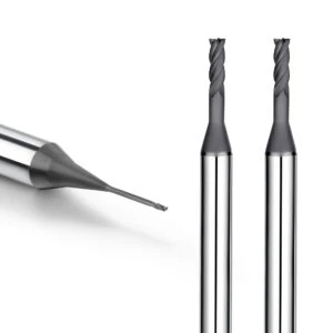
Machine Tool Hardware Inspection for Diamond End Mills: A Source of Failure Often Overlooked by Engineers
When edge chipping occurs, most engineers immediately blame tool parameters or material batches, but very few inspect the machine tool hardware. While diamond tools are incredibly robust, they are also highly sensitive precision instruments that demand exceptional system rigidity. If you attempt to utilize high-performance diamond end mills on a machine with a poorly maintained spindle or inadequate workholding, edge chipping is virtually inevitable.
Ceramic milling is a high-frequency, micro-cutting process where any minute hardware deviation is amplified into a severe mechanical shock at the workpiece edge. Before spending more money on premium tooling or changing your CAM paths, we strongly recommend conducting a diagnostic check against several easily overlooked hardware issues. If your underlying machining platform is unstable, even the best custom tooling cannot deliver its full cost-saving potential.
Spindle Radial Runout Exceeding 3 μm—A Fatal Blow to Diamond End Mills
In metalworking, a spindle runout of 10 μm might only affect dimensional tolerances, but in ceramic machining, it is completely unacceptable. Our field data demonstrates that the moment radial runout at the tool tip exceeds 3 μm, the wear rate of the diamond coating accelerates exponentially. If you are experiencing highly erratic tool life or immediate micro-chipping on a brand-new tool, you should check your spindle’s dynamic runout with a dial indicator.
Excessive runout forces a multi-flute diamond end mill for ceramic to take cuts with only one or two flutes while the others idle or scrape. This uneven loading triggers high-frequency radial vibrations and severe alternating stresses that cause rapid delamination of the tool coating. If your spindle runout exceeds 3 μm, you must first address spindle taper cleanliness or precision compensation before running high-end tools.
Why We Strongly Urge Customers to Discontinue the Use of Spring Collets and Switch to Shrink-Fit Tool Holders
We routinely advise precision workshops to abandon traditional ER spring collets for ceramic applications and transition to shrink-fit tool holders instead. If you are currently utilizing high-speed machining to produce small, intricate ceramic components, you need to evaluate your tool clamping rigidity. Due to their slotted design, spring collets have limited runout control and lack the clamping stiffness required to dampen the high-frequency vibrations of ceramic milling.
Shrink-fit holders use thermal expansion to achieve a 360-degree, high-strength interference fit that provides rigidity unmatched by spring collets. This extreme system stiffness ensures the cutting edges engage grain boundaries with maximum stability, minimizing tool deflection and lateral stress. If your finished parts still exhibit a pattern of microscopic serrations after optimizing your parameters, upgrading to a shrink-fit clamping solution is often the simplest fix.
The Practical Impact of Cutting Fluid Pressure and Cooling Placement on Preventing Thermal Shock Fracture in Ceramics
When reviewing a setup, we care less about whether coolant is present and more about its exact pressure and delivery target. If you are machining high-thermal-conductivity engineering ceramics and encounter sudden through-cracks mid-process, you must verify that the fluid hits the precise tool-workpiece contact point. Ceramics are highly sensitive to thermal shock; intermittent cooling causes localized temperature spikes followed by sudden quenching, which instantly fractures the crystal lattice.
Furthermore, high cutting fluid pressure is vital to flush out abrasive dust before it creates a destructive “lapping paste” effect that grinds down carbide tools for ceramics. In extreme cases, we integrate internal cooling channels directly into our custom diamond milling cutters to jet fluid from the tool tip. This targeted thermal management resolves persistent edge damage that remains completely unaffected by standard external coolant nozzles or parameter adjustments.






