


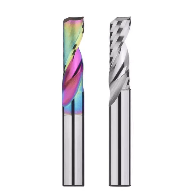
Last month, a long-standing U.S. client—a manufacturer of high-end signage and medical displays—sent us an email filled with frustration. They had just landed a major order requiring crystal-clear, 20mm-thick edges directly off the mill. Their shop supervisor was blunt: “No matter how we tweak the parameters, the edges come out cloudy and marred by tool marks. We’re stuck with manual polishing, which is killing our lead times and cutting our profit margins in half.”
This scenario is all too common. Over the past 15 years as a specialist in plastic-cutting end mills, we have seen this exact roadblock countless times. Many shops approach acrylic with an aluminum or woodworking mindset. The result? The plastic melts to the tool, or the edges chip so badly the parts are scrapped. Achieving a “mirror finish” directly off the machine isn’t about fixing errors in post-processing. It is determined the moment your end mill for acrylic touches the material.
To get haze-free edges, you must understand the physics of polymers. Even the sharpest standard carbide end mills will fail if the flutes aren’t mirror-polished or if the chip capacity is too small. Under high-speed friction, acrylic chips turn into a molten slurry that fuses to the part. This is why a precisely engineered single flute end mill with a massive evacuation channel is the only real solution, regardless of your other settings.
As long-term CNC plastic-cutting end mill suppliers, we know that every minute spent polishing is a minute of lost profit. A perfect finish is a precise balance of tool geometry, material type (cast vs. extruded), and chip load. Are you tired of looking at piles of semi-finished parts waiting for a hand-polish? Let’s look at why that “sweet spot” has been so elusive.
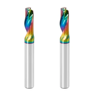
Why Does the Acrylic Cut in Your Workshop Appear Cloudy? Three Fatal Pitfalls
We often hear supervisors say: “Our CNC is rigid, and our vacuum and air-blow are at max. Why do the edges still look like they’re shrouded in fog?” Usually, the problem isn’t your machining center; it’s a process detail you’ve overlooked. Acrylic is an amorphous polymer sensitive to heat and shear. If conditions aren’t perfect, the surface suffers microscopic stress cracking—visible as “white edges” or cloudiness.
After analyzing hundreds of failures, we found that 90% aren’t due to poor craftsmanship. Instead, they happen because operators apply metal or wood-cutting logic to plastic. Cutting acrylic requires an “ultra-fine slicing” action and zero-resistance chip evacuation. If you’re fighting inconsistent finishes, you’re likely falling into one of these three traps.
Pitfall #1: The “Chip Evacuation Disaster” from Misusing Standard Tools
Many shops try to save on tooling by using carbide end mills designed for aluminum or wood. If you want an optically clear surface, this is a disaster. Metal-working tools have a thicker core for strength, which chokes the chip flutes. Woodworking bits, while sharp, aren’t designed for the continuous, ribbon-like chips that plastics produce.
When the tool is a mismatch, chips can’t slide out fast enough. They become compressed and packed into the flutes. This waste material then rubs against the freshly cut edge, plowing microscopic roughness into the surface. This is why a brand-new bit might start cutting “cloudy” after just a few meters. The flutes are clogged, and the tool is battering the material instead of slicing it.
Pitfall #2: Underestimating Heat Accumulation—The “Re-welding” Effect
Heat is the #1 enemy of a mirror finish. Acrylic has terrible thermal conductivity. More than 80% of the heat generated during the cut must be carried away by the chips. Often, supervisors crank the spindle speed but keep the feed rate low out of caution. This creates an dangerously low chip load.
Instead of clean cuts, the tool creates high-frequency friction. The waste material becomes a fine powder rather than “snowflakes.” This powder hits its melting point (around 100°C) and instantly “re-welds” to the sidewall. Once it cools, you’re left with a rough, lusterless surface and burrs. In CNC plastic cutting, it is always better to increase your feed rate to produce thicker chips that pull heat away from the part.
Pitfall #3: Incorrect Plunge Paths and Poor Vibration Control
The final mistake happens before the tool even starts its path. Many programmers use a vertical plunge (Z-axis entry). In acrylic, this is a cardinal sin. At the center of a vertical plunge, the tool’s velocity is zero. Chips can’t escape, heat spikes, and the plastic melts instantly, leaving a permanent burn mark. These micro-cracks then propagate along the entire cut.
Additionally, thin acrylic sheets are prone to high-frequency vibration, or “chatter.” If your workholding only secures the edges, the center will deflect and recoil under the lateral force of the plastic cutting end mills. This creates wave-like tool marks that ruin the linear refraction of light, making the edge look blurred. Use a ramp-in strategy (diagonal entry) and ensure your workholding is rock-solid to keep the material perfectly still.
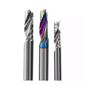
Why High-Quality Single Flute End Mills Are the Only Choice for Achieving a Mirror Finish
After testing dozens of tools with varying flute counts, our conclusion is clear: if your goal is an optical-grade finish on acrylic, a single flute cutting tool is your only choice. Many workshops use two- or three-flute cutters to increase feed rates, but more flutes mean less chip-evacuation space per edge. The chips cut by the preceding edge cannot clear out before the next one arrives, packing the flutes and ruining your surface finish.
When troubleshooting for clients in the US and Europe, we often run side-by-side tests comparing multi-flute cutters with a specialized single flute end mill. The results are always night and day: the single flute tool leaves a uniform, crystal-clear texture, while multi-flute tools leave a hazy film that you cannot polish away. A single flute endmill cuts only once per rotation, providing a long “idle” interval that acts as a vital cooling window for heat-sensitive plastics.
The Physical Chip-Evacuation Advantages of the Single Flute Design in Plastic Cutting End Mills
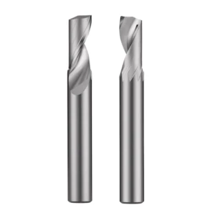
When you look closely at the cross-section of a tool made for plastics, you will notice a deep, curved geometry known as the O-Flute design. As a manufacturer of plastic cutting end mills, we design these wide, sweeping channels because acrylic doesn’t produce small metal chips; it forms long, gummy ribbons. The open volume of an O-Flute gives these ribbons a frictionless path to slide out and be flung clear of the workpiece by centrifugal force.
If the bottom of your tool’s flute is too shallow or rough, hot plastic chips will hesitate during evacuation. In milliseconds, this slight resistance turns into a tangled mass of melted plastic that clogs the cutting edge, spiking your spindle load. This is why we always recommend open O-flute designs for demanding cuts, like slotting 10mm plates, to keep the sidewalls perfectly haze-free.
How Mirror-Polished Flutes Eliminate Acrylic Chip Adhesion
Many machinists wonder why their high-end tools begin leaving fine, microscopic scratches on the acrylic surface after cutting just a few meters. The culprit is almost always the microscopic roughness left behind by standard grinding wheels inside the tool’s flutes. These tiny grinding marks act as anchor points for low-melting-point plastics, causing hot chips to snag, build up, and scratch your finish.
To stop this adhesion, the final step in our factory is subjecting the entire flute and rake face to a precision mirror-polishing treatment. This specialized process eliminates micro-grooves, allowing hot plastic ribbons to glide across the carbide surface like ice on glass. When using a mirror-polished end mill for acrylic, chips flow away like water, even on highly gummy, low-melting-point extruded sheets.
How We Suppress Tool Vibration by Controlling Micron-Level Tolerances During the Manufacturing of Solid Carbide End Mills
Beyond chip clearance, the silent killer of a mirror finish is high-speed spindle vibration, or chatter. Many shop managers assume their CNC machines are rigid enough, but they overlook how a tool’s own geometric imbalance ruins the cut. When grinding our carbide end mills, we maintain strict, micron-level control over Total Indicated Runout (TIR) and outer diameter tolerances.
Because a single-flute tool is physically asymmetrical, an imbalance of just three microns can create massive centrifugal forces at 20,000 RPM. On brittle materials like acrylic, this imbalance creates dense, wave-like ripple marks that destroy edge transparency. By dynamically balancing every tool before shipping, we ensure the edge cuts like a scalpel, stopping chatter at the source so your finish doesn’t rely on luck.
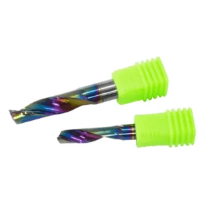
Real-World Case Study from European Workshops: How to Achieve a Crystal-Clear Surface Finish by Adjusting Speeds & Feeds
Last summer, we helped a German automotive trimmer machining 15mm-thick acrylic dashboards at 24,000 RPM whose edges were badly frosted and scorched. Looking at their catch-can, the waste material looked like fine white flour rather than clean plastic chips. This is a classic case of parameter imbalance: shops often assume that because plastic is soft, they should use high speeds and slow feeds, which actually grinds and melts the material.
The secret to direct-from-machine transparency is simple “chip control”—ensuring each cutting edge takes a substantial bite to pull heat away from the part. By lowering their spindle speed and stepping up the feed rate, we turned that melted white powder into thick, clean “snowflake” flakes. Optimizing your toolpaths this way allows the physical volume of the chip to absorb the heat, creating a massive leap in surface quality without upgrading your hardware.
Precision Calculation of Chipload: The Right Feed and Speed Match to Eliminate “Powdery Chips”
During on-site troubleshooting, we always calculate the shop’s feed per tooth, commonly known as the chip load. When cutting acrylic, if your chipload drops below 0.05mm (0.002″), your tool stops cutting and begins rubbing the material at high frequency. This intense friction spikes temperatures past the polymer’s softening point, turning your chips into a fine powder that ruins your edge.
Based on years of testing across various CNC platforms, we recommend keeping your chipload between 0.1mm and 0.15mm (0.004″ to 0.006″). For example, if you run your spindle at 18,000 RPM, your feed rate should be at least 1,800 mm/min (approx. 70 IPM) to produce plump, semi-transparent plastic granules. This optimal state prevents thermal damage to the sidewall and dramatically extends the working lifespan of your carbide end mills.
Climb Milling vs. Conventional Milling: Our Test-Based Conclusions
The choice between climb milling and conventional milling is a constant debate on CNC forums across North America and Europe. Traditional manuals often suggest conventional milling because it prevents the tool from grabbing and lifting thin sheet stock. However, our internal testing shows that these two methods impact the molecular chains of thermoplastic materials very differently.
In conventional milling, the tool edge enters the cut at zero thickness, causing a brief phase of sliding friction before it actually cuts. This friction instantly creates a microscopic layer of work hardening and burrs on your acrylic edge. For maximum optical clarity, we recommend climb milling so the edge slices through at maximum thickness instantly, keeping your cnc plastic cutting end mill suppliers performance clean and crisp.
Why We Recommend Using a Cold Air Blast Instead of Liquid Coolants During CNC Plastic Cutting
Flooding metal parts with coolant is standard practice, but dumping water-soluble cutting fluids onto highly transparent plastics often causes a disaster. We frequently see shops spray liquid coolants only to find a dense network of micro-cracks, or crazing, appearing a week later. Amorphous plastics suffer severe environmental stress cracking when exposed to certain chemical fluids while under mechanical stress.
For flawless temperature control and chip evacuation during cnc plastic cutting, we always install a dedicated cold air blast system. This setup uses a vortex tube to drop compressed air down to -20°C (-4°F), aiming a stream of dry, freezing air directly at the cutting zone. The forceful blast instantly blows chips out of the cut path, keeping your shop clean and protecting the glass-like clarity of your acrylic.
A Specialized Selection Guide for Acrylic End Mills—Tailored for Cast vs. Extruded Types
Many engineering managers across North America and Europe focus solely on sheet thickness and price, completely overlooking how the material was manufactured. Although cast and extruded sheets look identical, their molecular weights and thermomechanical properties are worlds apart. Attempting to run both materials with the exact same tooling and parameters guarantees widespread surface hazing or edge chipping on your line.
At our testing center, we have run thousands of prototype cycles on both sheet types to map their behaviors. Cast acrylic is harder and highly rigid, cutting much like a brittle metal, while extruded sheet has shorter molecular chains that make it prone to gummy stringing. To maintain a high yield of mirror-finish parts, you must match your material with a specialized end mill for acrylic designed for that specific polymer structure.
Cast Acrylic: How to Leverage High-Rigidity Carbide End Mills to Unlock Ultimate Transparency
Cast sheet is the gold standard for optical-grade displays because it cures naturally in a mold, leaving it virtually free of internal molecular stresses. When cutting cast material, your chips should look like dry, crisp flakes rather than melted strings. Because this material highly resists deformation, you can confidently chase a mirror finish, provided your tool has exceptional flexural strength and razor-sharp edges.
To unlock this optical clarity, we recommend using precision solid carbide end mills featuring an aggressively positive rake angle. Because cast stock is inherently brittle, any micro-deflection from a low-rigidity tool will cause microscopic chipping along the cut line, leaving a frosted edge. High-rigidity carbide blanks shear the polymer matrix instantly upon entry, leaving sidewalls so smooth they mirror the material’s natural light transmittance.
Extruded Acrylic: Fine-Tuning Single-Flute Chip-Evacuation Tools for Low-Melting-Point Conditions
If you handle high-volume signage or retail display orders, you are likely working with extruded sheets. This material is mechanically pressed, meaning its thermal stability is fragile and its processing window is incredibly narrow. On shop floors across the US, the most common “melted tool” catastrophes we see happen on extruded stock because a half-second delay in chip clearance snaps the bit.
To tame this melt-prone stock, your highest margin of error comes from a single flute end mill with modified geometry. We specifically narrow the tool’s cutting-edge width and increase the relief angle to minimize contact between the tool body and the freshly cut sidewall. Combined with a high-feed, skip-cut programming strategy, this physical design drops friction temperatures safely below the polymer’s melting point.
The Trade-off Between Single-Flute and Multi-Flute Tool Life in High-Volume Manufacturing
In high-volume sign shops, production supervisors constantly battle to balance fast cycle times against tooling consumption costs. In a rush for higher output, some shops blindly switch to double- or triple-flute plastic cutting end mills. They assume more flutes equal double the feed rate, but in reality, the abrasive plastic chips quickly dull multi-flute tools, causing white edges across production.
If your daily volume consists of sheets under 10mm and you prioritize long, unattended runtimes with consistent clarity, single-flute tools offer the lowest total cost. Their massive flute volumes prevent the thermal fatigue that ruins multi-flute tools during long runs. Multi-flute plastic tools only shine in specific roughing cycles where machine rigidity is flawless and heavy external air cooling is available.
Workshop Benchmarks for Evaluating CNC Plastic Cutting End Mill Suppliers
Many veteran machinists can quote cutting parameters from memory but rely purely on low prices or brand recognition when picking a tool vendor. However, polymer machining requires highly specific engineering; a shop that builds great metal-cutting bits cannot automatically build a great acrylic cutter. Without a deep understanding of polymer fluid dynamics and thermal deformation, a vendor’s tools will struggle to deliver consistent out-of-the-box mirror finishes.
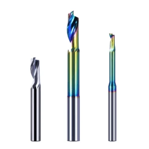
When vetting cnc plastic cutting end mill suppliers, look past the size of their product catalog and evaluate their real-world engineering support. In industrial B2B procurement, we always advise our peers to break free from the simple price trap. Instead, judge your suppliers across three strict operational pillars: their raw material sourcing, independent engineering R&D, and application support.
Standard 1: Does the Supplier Possess Independent R&D Capabilities Tailored to Engineering Plastics?
Designing cutting edges for acrylic, acetal (POM), and medical-grade PEEK requires entirely different geometry profiles. Acrylic is brittle and low-melting, requiring an ultra-sharp edge, while PEEK is incredibly tough and demands maximum vibration resistance. If your supplier’s plastic cutting end mills are just repackaged aluminum cutters with a new label, you will constantly battle edge chipping and stringy nesting.
A professional manufacturer must offer modular, customizable flute geometries backed by an independent prototyping and testing center. If you are struggling with tool adhesion on specialized or modified polymers, check if your supplier can engineer custom O flute profiles. Only a vendor capable of tuning relief angles based on a polymer’s specific glass transition temperature can solve tough production bottlenecks.
Standard 2: Raw Material Traceability—Why High-End Western Shops Insist on Premium Micrograin Carbide
In tool manufacturing, the grain size of your carbide rod determines the ultimate sharpness and lifespan of your cutting edge. Supervisors often wonder why two identical-looking single-flute bits perform completely differently under identical parameters. One cuts hundreds of meters cleanly, while the other leaves white streaks after fifty meters; the secret is the micrograin structure of the substrate.
To guarantee a crystal-clear, straight-off-the-machine finish, we source only premium ultra-fine or nano-grain carbide end mills stock. This dense, uniform grain structure allows our 7-axis grinders to hone a cutting-edge radius within a tight, single-micron tolerance. This prevents the microscopic fatigue-induced chipping common in coarser, low-grade rods, ensuring your surface finish remains identical from the first part to the last.
Standard 3: Technical Support Capabilities—Can They Calculate Your Optimal Parameters Within 24 Hours?
In precision B2B machining, even the world’s best cutting tool is reduced to scrap metal if paired with incorrect operational parameters. We often see clients pull a high-end bit out of the box, apply outdated parameter habits, and snap the tool within the first three minutes. In those critical moments, your supplier’s response time determines whether your spindle keeps turning or your production stalls.
Technically driven cnc plastic cutting end mill suppliers must deliver practical, actionable parameter solutions tailored to your specific machine capabilities. If you are setting up a difficult acrylic project and need to synchronize your spindle speed and table feed, you can leverage our engineering team. Send us your part blueprints, material spec sheets, and spindle metrics, and we will calculate your exact chiploads and path simulations within 24 hours.






