


In our 5-axis tool grinding workshop and through our global technical support tickets, we hear the same frustration from European and American clients every week: “Why is my tool life a rollercoaster ride when machining automotive valves?” Whether it’s C3604 free-cutting brass or the newer lead-free alloys, inconsistent tool life is a production killer.
Last month, a German client supplying hydraulic control valves to tier-1 automakers reached out with an emergency. Their automated line was failing. Their carbide milling cutters were supposed to last for 4,000 valve seats. Instead, they were seeing micro-chipping by the 2,500th piece. This caused the surface finish to fail tolerance, dragging down their Overall Equipment Effectiveness (OEE) and spiking their scrap rates.
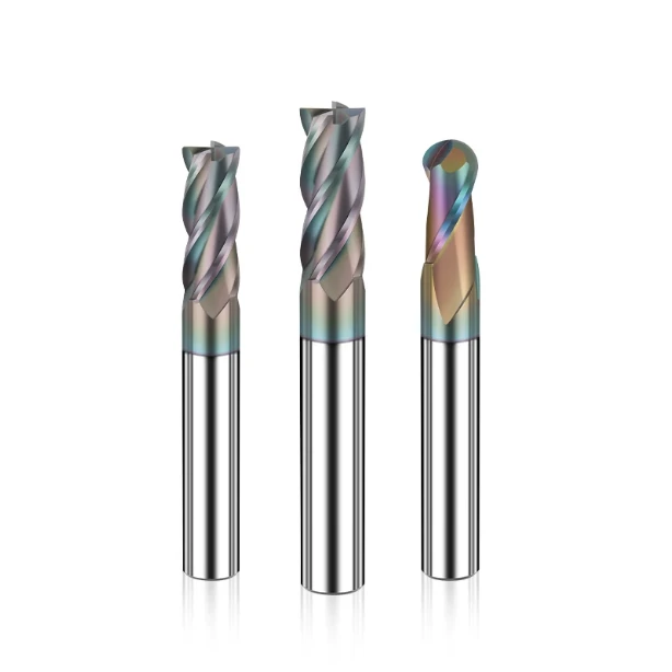
As an end mill supplier with 15 years in R&D, we know the “brass trap.” Many shops assume brass is soft and easy, thinking a standard flat milling cutter can handle it with zero effort. That is a mistake. Automotive valves require tolerances within ±0.005 mm and mirror-like sealing faces (Ra 0.4). This demands specialized geometry. During high-speed machining (HSM), brass’s high thermal conductivity leads to built-up edge (BUE). Without the right flute polish or edge sharpness, your tool won’t just wear down—it will snap.
We helped that client achieve a stable 45% increase in tool life. We didn’t do it with “magic.” We did it by optimizing helix angles, variable-pitch geometry, and implementing a specialized polishing end mill process. This eliminated burrs and stopped work hardening in its tracks.
We’ve spent 15 years on the front lines with process supervisors and tool buyers. We’ve distilled that experience into a “hardcore prescription” for brass. If you’re struggling with premature failure or “sticky” lead-free alloys, we’ve been there.
Look around your shop right now. Are there broken tools on the workbench that didn’t even last half a shift?
Case Study Review: Analyzing Premature Tool Failure in High-Volume Valve Production
In automotive manufacturing, high-tempo lines are unforgiving. We often see shops in the US and Europe push spindle speeds and feed rates to the limit to maximize metal removal. While this looks good on paper, it’s often counterproductive. Brass has a unique thermal expansion coefficient. If you don’t tailor your process to its chip formation, your end mill for brass will wear out faster than your operator can swap it.
Our field data shows that most tool-change stoppages aren’t caused by normal wear. They are caused by sudden, non-linear failures. In precision valve machining, if your tool can’t maintain micron-level stability for a full shift, your entire batch is at risk of failing airtightness tests. To fix this, we have to look at the physical contact interface where the “invisible killers” live.
The “Invisible Killer” in Valve Seat Machining: How BUE Destroys a Flat Milling Cutter
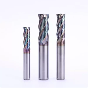
For flat-bottom cutting and corner clearing, the flat milling cutter is the workhorse. But brass is “sticky.” Many technicians overlook microscopic erosion caused by “cold welding.” At high RPMs, cutting heat concentrates at the tool tip. If the micro-finish inside your flutes isn’t perfect, brass particles will weld themselves to the cutting edge under high pressure. This is the BUE.
BUE is lethal because it takes over the job of the sharp cutting edge. It changes your rake angle and destroys your cutting trajectory. By the time you see “tearing” or chatter on the workpiece, the BUE has likely detached and reformed multiple times. Each time it peels off, it takes a microscopic chunk of your carbide with it. This leads to sudden, brittle fractures with zero warning.
16 Years of Workshop Experience: Why Leaded vs. Lead-Free Brass Requires a Different Carbide Milling Cutter
As our North American clients transition to eco-friendly, lead-free alloys (like C46400), they often see tool life plummet by 50%. We’ve analyzed these dynamics in the lab and on-site. In traditional leaded brass, the lead acts as a “natural lubricant.” It helps chips break into short, brittle pieces, keeping cutting forces low and protecting the carbide milling cutter.
Lead-free brass is a different beast. Without that lubrication, the material becomes incredibly tough and ductile. During our tests on lead-free valves, we saw chips transform into “tenacious ribbons” that entangle spindles. Because lead-free brass work-hardens so quickly, your tool is essentially cutting through something as tough as stainless steel. You cannot use standard copper-alloy geometry here. You need superior toughness and impact-resistant edges to survive the mechanical abrasion and thermal fatigue.
A Look at Geometry and Materials—How We Customize Carbide Milling Cutters for Extended Tool Life
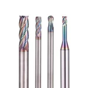
When fighting premature wear in high-volume machining, top-tier raw material isn’t enough. As you push multi-axis machining centers with heavy feeds, the cross-sectional geometry and micro-edge profiles dictate if a tool survives the shift. As a manufacturer of the carbide milling cutter, we dynamics-tune our tool designs to match your shop’s specific spindle harmonics, fixture setups, and machine rigidity.
In our R&D tests, balancing carbide hardness and toughness requires a calculated compromise. When cutting brass housings with uneven material density or heavy casting skins, we ditch the pursuit of pure hardness. Instead, we select ultra-fine grain substrates with high flexural strength and apply targeted PVD coatings. This custom approach might add upfront communication time, but the predictable tool life pays off across automated lines.
Addressing High-Frequency Vibration in Valves: Why We Insist on Variable Indexing for the Specialized End Mill for Brass
If you have ever heard a high-pitched spindle squeal while profiling thin-walled valve bodies, you know how fast harmonic resonance destroys a sharp edge. Standard symmetrical flutes hit the material at identical intervals, creating cyclic force spikes that shatter carbide. When building a specialized end mill for brass for North American machine shops, we eliminate this by implementing variable indexing and asymmetrical helix angles.
By staggering the entry and exit timing of each flute, we physically disrupt the chatter frequency at its source. Beyond dampening vibration, we meticulously fine-tune the relief angles based on the specific brass grade. Too narrow, and the flank rubs the part, causing work hardening and thermal growth; too wide, and the edge loses backing support and chips. Finding that sweet spot is our secret to keeping your spindle quiet and your tool intact.
The Key to Precision Sealing Surfaces: How Micro-Edge Preparation on a Polishing End Mill Cuts Friction
Machining metal-to-metal valve seats for airtight, leak-free performance leaves no room for micro-jagged edge tears. Under microscopic analysis, we found that localized heat zones are usually caused by friction from chips dragging up the flute face. To fix this, we integrated a secondary mirror-finishing stage into our grinding process to create our premium polishing end mill lineup.
This micro-polishing goes beyond the flutes; it passivates and rounds the cutting edge at a micron level. This precise edge preparation removes the micro-fractures left behind by standard grinding wheels. When the tool hits the copper alloy, it shears cleanly, drastically dropping the friction coefficient. Chips slide out effortlessly, dumping heat into the hopper rather than the tool tip, allowing you to bypass secondary manual lapping entirely.
Workshop Practical Parameters: Squeezing Maximum Value from a Flat Milling Cutter Through Strategy
Backing off your feed rates to make a tool last longer is a losing game that destroys your cycle times. Our shop floor experience proves that optimizing your tool paths and tweaking your step-over (Ae) and depth of cut (Ap) unlocks hidden capacity. When your spindle load meter starts fluctuating mid-shift, don’t swap the tool yet; a smart toolpath adjustment lets a worn flat milling cutter finish the batch reliably.
This strategy requires a solid grasp of non-ferrous chip dynamics. When running high-volume brass jobs, we always tell clients to stop running traditional full-slot, heavy-radial passes. Switching to trochoidal paths or high-speed pocketing distributes the thermal and mechanical loads evenly across the flutes. This shifts the wear pattern from localized chipping to a gradual, predictable recession, saving your tool budget without dropping your output.
Deep-Cavity Control Valve Milling: Protecting the End Mill for Brass from Secondary Chip Damage
When plunging deep slots inside fluid control valves, tools rarely snap from lack of machine rigidity. The real culprit is recutting trapped chips at the bottom of the pocket. At depths past three times the tool diameter, standard flood lines fail to wash chips clear. The loose brass gets packed into the cavity, where a spinning end mill for brass forces it back into the cutting zone, spiking spindle torque instantly.
We counter this by altering both the plumbing and the toolpath entry. We advocate for through-tool coolant or high-pressure side air blasts adjusted to blast the pocket floors clean. On the programming side, we replace straight vertical plunges with helical interpolation or smooth ramping to keep the chip evacuation channel wide open. Never let your flutes chew on loose debris; it is the golden rule for deep-cavity safety.
Practical Adjustments for Feed Parameters and Coolant in High-Volume Dynamic Milling
For heavy roughing on brass valve castings, we highly recommend shifting your shop to High-Efficiency Milling (HEM) strategies. HEM uses a light radial step-over—around 5% to 10% of the tool diameter—combined with a deep axial cut using the full length of the flute. This spreads the heat across the entire tool body instead of cooking the corner radius, allowing you to safely double or triple your traditional feed per tooth (Fz).
The danger zone with HEM on brass is the sudden thermal shock from improper cooling. Because brass transfers heat so fast, blasting an aggressive HEM path with standard flood coolant causes immediate thermal cracking along the carbide edge. We get far better tool life using high-pressure, low-volume MQL systems or precisely aimed mist lines. Keep that temperature curve flat, and your carbide milling cutter will scream through parts without shattering.
Eliminating Surface Defects in “Polish-Free” Processes: The Application of Polishing End Mills on Sealing Surfaces
Achieving leak-free performance on automotive valve seats requires flawless surface integrity. Many machine shops rely on traditional methods, using a standard mill for roughing and manual lapping for final finishes. However, manual secondary operations cause micro-geometric distortions during mass production due to human error. To break this bottleneck, we guide clients toward a “single-pass finishing” strategy using a specialized polishing end mill.
Eliminating defects requires more than a shiny tool; it demands absolute machining system rigidity. During the final finish pass, tiny spindle vibrations or tool holder runout create visible fish-scale patterns. That is why we do more than just drop off custom tooling at client facilities. We dive deep into your CNC programming parameters to ensure the non-ferrous metal undergoes a perfect shear rather than a micro-tear.
Bidding Farewell to Manual Lapping: Milling Ra 0.4 Valve Seats with High-Mirror Polishing End Mills
Milling a consistent Ra 0.4 mirror finish directly onto a flat brass valve seat is impossible with standard tooling. Microscopic analysis shows that standard cutting edges possess micro-roughness that rips the brass surface instead of shearing it. By using ultra-fine-grain substrates and polishing the helical flutes, our specialized polishing end mills lower the friction coefficient. This allows the ductile material to slide smoothly across the slip planes.
For the setup, we recommend keeping your axial stock allowance strictly between 0.05 mm and 0.1 mm. Leave too much material, and high cutting forces cause tool deflection and chatter; leave too little, and the tool rubs and extrudes, causing rapid work hardening. Combined with high surface speeds (Vc) and light feeds, these mirror-finish tools eliminate manual lapping while guaranteeing absolute geometric roundness.
Preventing Valve Edge Burrs: How Climb vs Conventional Cutting Impacts Your End Mill for Brass
Brass tends to form nasty exit burrs at the sharp intersections of automotive valve manifolds due to its high ductility. This forces shops to add costly manual deburring benches, slowing down the entire automated production line. Our field tests prove that alternating between climb and conventional milling paths controls chip thickness. This simple programming shift dictates whether the chip exits from thick-to-thin or thin-to-thick.
While climb milling delivers the best surface finish, blindly using it on high-copper brass alloys can spike tool shock on entry. This sudden impact triggers micro-chipping on a standard end mill for brass. We prefer conventional milling to rough out the heavy cavities and protect the tool. We then switch to climb milling only for the final finishing pass, extending edge life by nearly 30%.
Rejecting Trial-and-Error: How Automotive Procurement Chooses Highly Stable End Mill Suppliers
In automotive parts manufacturing, tooling supply chain stability matters far more than saving a few pennies on unit price. When production runs 24/7, a procurement department focused solely on the cheapest quote forces engineers to pay for it later in downtime and scrap. As a front-line end mill supplier, we know that auditing a tool factory requires looking past sales pitches and checking their metric control.
Top-tier tool vendors give shop supervisors peace of mind. If your production line is chasing aggressive cost-per-part optimization targets, look closely at the supplier’s grinding department. They should run premium 5-axis CNC grinders from Walter or ANCA and use micron-level laser measuring systems. Only factories with this level of equipment can guarantee total dimensional consistency across a 50,000-part run.
Escaping the Low-Price Trap: Material Consistency for the Carbide Milling Cutter
The secret failure point of cheap cutting tools across North American machine shops is the quality of the carbide rod substrate. Brass machining exerts lower cutting forces, but it provides instant feedback on the material’s transverse rupture strength. Micro-voids or cobalt segregation in the rod cause unpredictable, premature edge chipping under high-frequency impact. This is why our incoming inspection standards for raw carbide are fiercely strict.
If tools from the same batch yield wildly erratic tool life under identical feeds and speeds, your supplier has a traceability issue. A certified end mill supplier must provide metallographic inspection sheets for every rod batch to guarantee uniform hardness. Controlling carbide consistency at the source is the only way to ensure predictable machining cycles on your shop floor.
Tech Support Commitments: Why Custom Prototyping from End Mill Suppliers Cuts Real Costs
There is no such thing as a universal, one-size-fits-all cutting tool in precision CNC manufacturing. The ideal flute profiles and edge prep parameters change completely between free-cutting C3604 brass, lead-free eco alloys, and high-copper bronzes. Catalog distributors who just drop boxes and don’t understand shop conditions are useless when your automated line hits a wall.
If stringy, ribbon-like lead-free brass chips are wrapping around your spindle, or you can’t hit your Ra 0.4 finish target, let’s talk. We want you to analyze your machine rigidity, spindle RPM, and fixturing setups with us. Feel free to send us your toughest part prints, target cycle times, and material specs. Through custom geometry adjustments and real-world prototyping, we will push your cycle efficiency to the absolute limit.


