


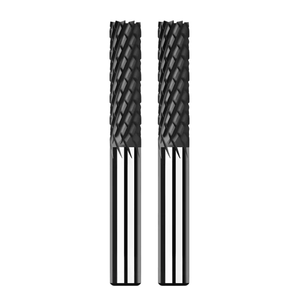
Last month, a long-standing client—a workshop supervisor specializing in aerospace CFRP components—sent us an urgent email. The high-resolution photos he attached showed a nightmare scenario: thick-section structural parts with severe interlayer delamination. At the exit edges, where the fiber bundles should have been severed cleanly, the material had torn into distinct, feathery layers. He was blunt: “The moment our long milling cutter enters a deep cavity, delamination spirals out of control, risking tens of thousands of dollars in scrap.”
This scenario is a classic challenge we have resolved repeatedly over our 16-year history of manufacturing specialized carbon fiber cutting tools. Many peers fall into the trap of assuming a generic end mills for carbon fiber can be treated like aluminum tooling. In reality, carbon fiber isn’t “cut” in the traditional sense; it must be sheared through precise mechanical force. If your chip flutes are inadequate or axial forces are unbalanced, those high-hardness fibers act like tiny pry bars, prying the resin matrix apart.
Using standard carbide without high-performance diamond coated end mills is the primary culprit behind poor surface finish and fiber pull-out. Dull edges lead to intense compressive forces that destroy the part’s integrity. For facilities prioritizing profitability, the secret lies in securing a reliable supply of wholesale end mills to guarantee consistent tool life. When facing high-intensity machining, how can you use micro-geometry to contain these stresses and ensure every cut is executed with absolute precision?
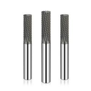
Why Do Western Shops Consistently Experience Delamination? The Mechanics of CFRP Failure
In our daily technical support, we see veteran machinists struggle when applying traditional metalworking logic to anisotropic materials like CFRP. Unlike homogeneous alloys, carbon fiber has extremely low interlaminar shear strength, meaning it resists fracture inconsistently across the resin matrix. Through extensive on-site testing, we’ve found that delamination occurs the moment localized machining stress exceeds the bonding strength of the epoxy resin.
This failure typically spikes during tool entry and exit, where unbalanced forces cause the material to tear laterally. Using generic end mills for carbon fiber often exacerbates this because they lack the specific geometries needed to neutralize internal stress concentrations. We’ve learned that only by precisely adjusting the mechanical load through tool design can you prevent the elastic recovery of the material from forcing the layers apart.
Axial Tensile Stress: Why Traditional Carbon Fiber Cutting Tools Cause Fabric Lifting
A common mistake we see in Western workshops is using standard single-flute “upcut” spirals for composite sheets. Our project post-mortems show that these carbon fiber cutting tools generate intense upward axial tensile stress during high-speed rotation. This force acts directly on the top surface, peeling the fiber bundles away from the matrix before they can be sheared, resulting in a fuzzy, unfinished edge.
This lifting force is especially destructive during dry machining or high-speed slotting where fixturing might be less than rigid. We’ve found that blindly increasing spindle speed only softens the resin further due to heat, making the “peeling” effect even worse. The solution lies in introducing a counter-acting downward stress to balance the load, a geometric shift we prioritize in our custom designs.
Edge Dullness: The Vicious Cycle Without Diamond Coated End Mills
Many procurement managers fall into the trap of focusing on the “per-tool price” of uncoated carbide. In our experience, using uncoated tools on CFRP is like using a plastic knife to cut sandpaper; the abrasive fibers cause severe flank wear almost immediately. Without the ultra-high hardness of diamond coated end mills, the cutting edge radius increases exponentially, leading to a rapid loss of precision.
Once the edge blunts, the process shifts from shearing to “squeezing,” which causes localized temperatures to skyrocket. If the heat exceeds the resin’s Glass Transition Temperature (Tg), the matrix loses its ability to anchor the fibers, triggering massive fiber pull-out. This is a vicious cycle that no amount of parameter fine-tuning can fix once the tool’s physical edge has failed.
Tool Overhang: Why Delamination Risks Double with a Long Milling Cutter
When edge-trimming components over 50mm thick, shops often reach for a long milling cutter without considering the cubic degradation of tool stiffness. Our field measurements using displacement sensors confirm that excessive length-to-diameter ratios lead to severe, high-frequency chatter. Each vibration acts like a microscopic hammer, tearing the interlaminar structure apart before the fiber can be cleanly severed.
Data indicates that this radial runout instantly disrupts the cutting equilibrium, causing the fiber bundles to oscillate and delaminate. To mitigate this, we advise against aggressive full-slotting and instead favor trochoidal milling with small radial step-overs. By using these strategies, we help shops compensate for the inherent rigidity deficiencies that come with long-reach applications.
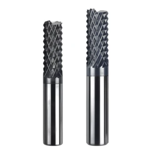
The Geometric Solution to Delamination: How We Customize Exclusive End Mills for Carbon Fiber
Having recognized the destructive forces in cutting mechanics, we tackle these abrasive fibers head-on through precise tool geometry. Our workshop regularly receives complex blueprints from across North America and Europe, ranging from high-density panels to hybrid composites woven with Kevlar. Based on our 16 years of customization experience, we know that standard off-the-shelf tools simply make too many compromises on flute spacing and rake angles, which quickly skyrockets your scrap rates.
To eliminate interlayer tearing in production, we analyze our clients’ CAM programming to make micro-adjustments to the cutting edges based on ply orientation. Our core philosophy is to use the tool’s helix direction and staggered edge arrangement to create a high-pressure “locking zone” around the workpiece. By customizing our end mills for carbon fiber, we channel the radial cutting forces inward toward the center of the plate, neutralizing delamination stresses at their inception.
Compression Tooling: How Opposing Cutting Forces Perfectly Lock Down Carbon Fiber Edges
If your shop is machining double-sided carbon fiber panels that demand pristine surface finishes on both faces, a compression design is our go-to recommendation. The engineering elegance lies in combining diametrically opposed helix directions on a single tool: a downcut geometry near the shank and an upcut geometry near the tip. During machining, the upcut edge pulls the bottom layers upward while the downcut edge pushes the top layers downward.
This opposing dynamic generates inward-acting, self-locking compressive stresses that prevent the outermost fiber plies from flaring outward or chipping. However, as a fellow engineer, I must caution you that the geometric crossover zone must be precisely aligned with the center of your material stack. If your panel thickness fluctuates or your Z-axis tool-setting is slightly off, this balance breaks down, meaning this method demands highly accurate workholding and fixture flatness.
“Pineapple Teeth” and Corn-Cob Structures: How Multi-Point, High-Frequency Shearing Inhibits Interlaminar Delamination
For high-volume production or heavy structural components in Western automotive and aerospace shops, we find that staggered, chip-breaking geometries are the most reliable option. Often called “pineapple teeth” or corn-cob cutters on the shop floor, these carbon fiber cutting tools replace traditional continuous flutes with a matrix of miniature helical scales. During high-speed rotation, the tool applies a rapid succession of microscopic, intermittent shearing actions rather than a continuous lateral thrust.
The advantage here is the tool’s ability to pulverize tough fiber bundles into fine dust-like chips before they can form long, continuous tears. Because the micro-chip load is distributed across hundreds of tiny cutting points, it eliminates the localized stress spikes that pry composite layers apart. While they don’t achieve the mirror-like sidewall finish of multi-flute finishing tools, their stability in suppressing delamination during heavy roughing is unmatched by standard solid spiral designs.
Machining Deep Cavities and Thick Plates: A Practical Approach to Optimizing the Rigidity of Long Milling Cutters
When tackling deep-reach aerospace components, the most common pitfall engineers fall into is scaling up the flute length of a standard tool proportionally. We once helped a client troubleshoot severe deep-slot tearing where they used a modified standard long milling cutter at a 40mm depth. The slot floor was riddled with whitish stress marks caused by tool deflection and retraction chatter. The fix required us to re-engineer the ratio between the core diameter and flute depth.
Our manufacturing strategy was to slightly reduce the flute depth, allowing us to increase the tool’s core diameter by 15% to 20% for added rigidity. We also incorporated unequal indexing to disrupt harmonic resonance cycles that cause chatter at extreme depths. While the shallower flutes require a strong negative-pressure vacuum system to pull dust out, the added stiffness drastically suppresses tool-tip oscillation, keeping your cuts square and delamination-free.
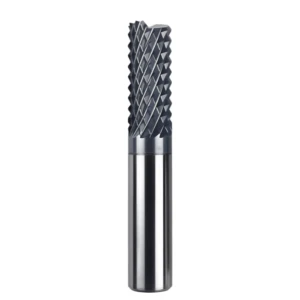
Diamond Coating: Why Long-Life Diamond-Coated End Mills Are the Standard for Quality Control in Western Factories
In any composite machine shop, we all know that the real enemy isn’t a tough cycle time—it’s process unpredictability. When running automotive or motorsport components with micron-level tolerances, an uncoated carbide tool can lose its edge geometry after just three parts. This creates a quality rollercoaster that ruins production efficiency. Our experience proves that running an ultra-hard nanodiamond layer is the only way to lock down your quality control over long production cycles.
Overseas workshop supervisors agree that high-performance diamond coated end mills are about more than just tool longevity; they lock your process window in place. With a microhardness closely matching natural diamond, these tools withstand hundreds of meters of abrasive fiber wear without visible edge degradation. By eliminating tool wear from your CNC equation, your programmed cutting forces and surface finishes stay identical from the first part to the last.
Real-World Wear Resistance Testing of CVD Diamond Coatings: Documenting Cutting-Edge Retention in a Live CNC Environment
To document how our coatings hold up under real shop floor stress, our R&D team ran extended field tests on high-density CFRP wing panels in Europe. Using standard uncoated carbide tools, we recorded flank wear exceeding 0.2mm after just 15 meters of cutting, which immediately caused visible interlayer chipping. We then swapped in our proprietary diamond coated end mills under the exact same parameters and dry-cutting conditions.
After a cumulative cutting distance of 150 meters, polarizing microscopes confirmed that our microscopic edge morphology remained remarkably intact. The CVD diamond crystal structure effectively shielded the carbide’s cobalt binder from erosion and reduced edge radius dulling by over an order of magnitude. This long-term edge retention ensures the tool tip cleanly shears through tough fibers instead of bluntly rubbing the resin, stopping late-stage delamination at the source.
Troubleshooting Coating Peeling: How We Help Western Clients Resolve Coating Failure Issues Under High-Load Conditions
Let’s be candid: diamond coatings are not a mythical panacea, and we have seen them fail under heavy, unoptimized shop loads. A U.S. medical device manufacturer once contacted us because their coating was flaking off in large patches during high-feed roughing. Our laboratory fracture analysis of these failed carbon fiber cutting tools showed that the issue wasn’t abrasive wear, but rather insufficient interfacial adhesion strength between the carbide substrate and the diamond layer.
To solve this under high-load conditions, we modified our chemical manufacturing process to focus heavily on the substrate’s preliminary treatment. We implemented a deep ultrasonic cobalt-leaching technique and introduced a specialized transition layer before diamond deposition to buffer thermal expansion mismatches. We also advised the shop’s programmers to ditch sudden, jerky toolpath entries for smooth, helical ramping strategies, which successfully stopped the premature peeling.
The True ROI of High-Performance Diamond Coated End Mills—Viewed Through the Lens of Cost-per-Part
Traditional purchasing departments often focus exclusively on the high upfront invoice price of a diamond-coated tool and shake their heads. However, when we break down the operating numbers with workshop managers who track overall profit margins, the focus shifts to comprehensive cost-per-part. In a composite plant running uncoated tools, frequent machine downtime for tool changes their OEE, while the financial burden of scrapped parts drove total production costs through the roof.
Once they transitioned to sourcing our custom-coated tools in bulk through reliable wholesale end mills channels, their tool life skyrocketed twelvefold. Their CNC spindles ran continuously for multiple shifts without downtime for tool adjustments, and manual edge-sanding costs in downstream departments dropped to zero. Factoring out the hidden expenses of scrap and machine downtime, their actual data revealed a 30% reduction in true cost-per-part, proving the financial value of operational stability.
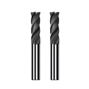
Programming and Practical Strategies to Mitigate Delamination Risk: Our Process Optimization Solutions for Workshop Supervisors in the West
After years in tool manufacturing, we have observed that delamination issues rarely blame the cutting tool alone. Even when we supply top-tier end mills for carbon fiber, improper programming logic and operational errors create scrap parts. While providing technical support in North America and Europe, we notice veteran operators habitually apply a traditional “metalworking mindset.” Prioritizing maximum chip evacuation volume or constant cutting loads on these fragile laminates is highly counterproductive.
Drawing from 16 years of composite project data, our team developed a practical methodology to systematically prevent delamination. True process optimization uses specialized programming techniques to artificially compensate for the structural vulnerabilities of the material. This requires a holistic perspective to analyze the complex forces between the cutting tool and the abrasive plies. Our solutions guide you through parameter balancing and toolpath control to ensure high yield rates on your shop floor.
Balancing Feeds & Speeds: How to Avoid Inter-laminar Tearing Caused by Aggressive Cutting
To boost production output, workshops instinctively increase feed rates, but this remains the root cause of edge tearing. If the feed per tooth (IPT) is set too aggressively, the cutting edge generates intense positive pressure before severing the fibers. Conversely, setting the spindle speed (RPM) too high generates excessive frictional heat, causing the resin matrix to soften. When optimizing carbon fiber cutting tools, you must target the sweet spot where shearing frequency clears chips without exceeding interlaminar shear strength.
We typically recommend starting with a conservative strategy of high spindle speeds coupled with moderate-to-low feed rates. However, a major pitfall occurs if the feed rate is too low; the tool dwells too long, creating heat that ruins the epoxy resin. We dynamically calculate a balanced feed rate calibrated to the tool diameter and flute count to preserve sharpness and facilitate cooling. Accepting a modest 10% reduction in cycle time is a small price to pay to save expensive composite panels from the scrap heap.
Up-milling or Down-milling? Our Recommended Toolpath Strategies for Machining with Carbon Fiber Cutting Tools
The debate regarding up-milling versus down-milling (climb milling) remains a staple within the CNC community. While climb milling is the gold standard for machining metals, processing high-modulus composites with carbon fiber cutting tools is far more complex. In climb milling, the cutting edge enters the material at its thickest point, shielding the edge from hard spots to extend tool life. However, the downward force generated at entry can easily induce bottom-layer delamination on thin-walled parts.
When processing precision components for Western clients, we employ a hybrid programming approach tailored to the directional forces acting on the edges. During finishing phases, we favor climb milling because its radial cutting forces are directed inward toward the material core, stabilizing surface fibers. Yet, at critical tool exit points, we switch to conventional up-milling to alter the disengagement angle of the cutting edge. This flexibility ensures the final fiber strands are cleanly sheared rather than pulled apart.
Entry and Exit Path Design: How Ramping Protects the Leading and Trailing Edges of Carbon Fiber Plates
Delamination frequently occurs at the precise moments when a cutting tool enters or exits the material, accounting for over 80% of our troubleshooting cases. If a long milling cutter enters the composite via a direct vertical plunge, the axial force acts like a punch, causing circular delamination. To avoid this critical flaw, we mandate that all custom machining paths use helical ramping or arc entry techniques. Gliding smoothly into the material at a slight angle resolves the instantaneous impact force into manageable horizontal and vertical components.
During the exit phase, the greatest threat is a breakout fracture occurring at the very last moment of the cut. As the tool reaches the end of the profile, the remaining supporting material thins out, making fibers susceptible to tearing under tool thrust. Our standard practical technique involves programming an overshoot path, decelerating the exit speed, or utilizing a sacrificial backing board to provide lateral support. These technical details are precisely what separate a tier-one aerospace manufacturer from an ordinary machine shop.
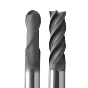
Supply Chain Cost-Reduction Strategies: How Wholesale End Mills Ensure Consistent Yields in Batch Processing
Having overcome the technical hurdles of cutting geometry and programming paths, we must confront the financial realities of the ledger. As manufacturing peers, we understand that producing a single perfect sample in a lab is easy; the real challenge is turning out thousands of identical, defect-free parts on a production line. For Western factories facing high raw material and labor costs, unexpected tool failure renders all prior process optimization futile. True cost reduction requires shifting from buying cheap tools to managing a highly stable supply chain.
Sourcing reliable wholesale end mills directly from the manufacturer is about eliminating variables within your factory’s operational management, not just securing bulk discounts. Once tool consumption reaches a production scale, supply chain responsiveness and quality consistency directly determine your Overall Equipment Effectiveness (OEE). If your automated lines are constantly adjusting work offsets to compensate for dimensional fluctuations between tool batches, your consumables strategy is eating your profit. Here is how high-yield workshops construct defensive barriers at the supply chain level.
The Pain Point for Large Western Factories: Why Batch Consistency in Wholesale End Mills Must Be Locked Down Once the Manufacturing Process Is Established
The most dreaded issue we encounter in high-volume B2B technical support is inexplicable tool failure during automated runs. Clients often report that, despite using identical programming parameters, a new batch of tools exhibits severe edge tearing or premature coating delamination. When we conduct microscopic fractography analysis on these failed tools, we often discover minute deviations in the carbide substrate’s micro-grain structure. Even a 0.5-micron thickness irregularity in the diamond layer destroys batch-to-batch consistency.
If you are running high-load automated production lines, you must lock down specific tool batches to pass rigorous aerospace or automotive quality audits. As a manufacturer supplying high-volume wholesale end mills to the West, we enforce rigid standardization over our cobalt-leaching treatments and CVD furnace temperature profiles. When every end mill shipped to your workshop achieves micron-level replication in cutting-edge radius and coating stress, your process window remains completely stable. This manufacturing control is the only way to suppress delamination rates below a strict 0.1% threshold.
Wear Monitoring and Scheduled Replacement: Establishing Standardized Workshop Tool Life Management SOPs Backed by Wholesale Supply
With consistent tool quality serving as your foundation, the next step is translating engineering data into standardized operating procedures (SOPs) on the shop floor. In high-efficiency CNC workshops, seasoned operators never wait until a workpiece exhibits visible delamination or chatter before changing a tool. By that point, the expensive component is already scrap. If you are managing a multi-station team, you can leverage our wholesale supply cycles to establish a mandatory, preventative tool replacement schedule.
We assist supervisors in documenting the linear correlation between tool flank wear and cutting distance under their specific workshop conditions. By determining the critical cutting distance a diamond coated end mills can safely traverse without causing delamination, we configure an automated tool-life counter in the CNC panel. For instance, once the tool hits a 80-meter limit, the system halts operations for a scheduled change, regardless of visual sharpness. This preventive strategy avoids stock-outs, protects raw material assets, and secures a zero-defect production standard.






