


Last week, a long-standing American client emailed us venting their frustrations. They had just secured an order for miniature electronic heat sinks made from C11000 pure oxygen-free copper. Initially, they planned to pull a few standard tools from the crib and get straight to work, assuming high-performance cutters would do the job. However, before machining the third part, the shop floor hit a massive bottleneck: severe chip adhesion, terrible surface burrs, and a tool snapping clean in half inside a deep slot.
This scenario is all too familiar to us. Over 15 years of hands-on shop-floor experience, we have seen countless precision machinists stumble into this exact same pitfall. Many seasoned pros wonder why those top-tier carbide end mill cutter tools—which effortlessly slice through titanium or stainless steel—completely fail when confronting seemingly “soft” copper.
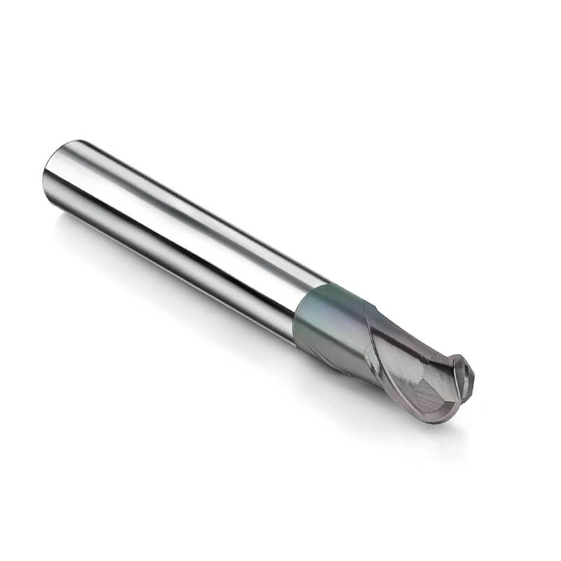
The root of the issue lies in pure copper’s aggressive stickiness and high ductility. Conventional carbide tools prioritize edge toughness, using heavy hone or chamfers to muscle through hard materials. But on copper, cutting temperatures skyrocket instantly, welding chips to the cutting edges to form a BUE. To fix this, you need a specialized end mill for copper engineered with razor-sharp geometry and mirror-polished evacuation paths.
For complex 3D contours or electrode finishing, the chip clearance of a high-precision milling cutter ball nose determines your surface quality. Savvy overseas buyers know that sourcing from a capable china end mill milling cutter factory isn’t about chasing the lowest price. It’s about finding a technical partner who designs tools that genuinely maximize shop-floor ROI.
16 Years of Shop Floor Reality: Why Can’t Standard Carbide End Mills Handle “Sticky” Pure Copper?
Every month, we receive dozens of technical support inquiries from shop supervisors across North America facing the same issue. Many harbor a common misconception: if a tungsten cutter can slice through hardened mold steel like butter, it should easily handle soft copper. However, those general-purpose carbide end mill cutter tools frequently fail, sometimes after cutting just a few meters. Standard tools are optimized for high-tensile materials, meaning their cutting edges feature micro-honing or negative land geometries to prevent chipping under heavy loads.
When applied to pure copper, this high-strength edge design becomes a fatal flaw. Copper is incredibly ductile; if the tool edge pushes or extrudes the material instead of cleanly shearing it, the metal undergoes massive plastic deformation. Without a sharp positive rake, cutting forces spike, causing the gummy copper chips to jam inside the channels. This obstructed evacuation breaks the thermal balance, causing localized heat to skyrocket and triggering premature tool failure.
The Cost of BUE: How We Helped a U.S. Client Solve the Nightmare of Copper Chips “Welding” Themselves to the Cutting Edge
Last summer, an Ohio job shop ran into a costly crisis while milling a high-volume batch of EDM copper electrodes. Within an hour of running, heavy tearing marks ruined the workpiece finishes and dimensional tolerances began to drift. Under a microscope, the client’s engineers saw a layer of blackened copper violently friction-welded onto the cutting edges. This Built-Up Edge (BUE) completely altered the tool’s geometry, destroyed micron-level tolerances, and caused the end mill for copper to snap during deep slotting.
To salvage the project, we swapped their standard cutters for specialized tools featuring aggressive rakes and mirror-polished flutes. In copper milling, success relies on evacuation speed—chips must slide away the millisecond they are sheared to prevent heat buildup. We also advised switching from water-soluble emulsions to high-pressure oil or MQL systems directed right at the cutting zone. This strategy tripled their tool life and eliminated frequent stoppages for manual chip clearing.
The Catastrophic Reaction of Aluminum-Based Coatings: Why You Must Never Use End Mills Coated for Steel or Aluminum to Cut Pure Copper
Another hidden trap into which even veteran machinists fall is ignoring the chemical affinity of modern tool coatings. Many shops habitually reach for premium inventory featuring AlTiN or AlCrN coatings when tackling copper jobs. They assume these high-performance nano-coatings, known for extreme wear and heat resistance, will provide an extra layer of protection. However, our field testing confirms that aluminum-based coatings are a total disaster when paired with pure copper.
At high cutting temperatures, the aluminum within the coating reacts chemically with the copper workpiece, causing elemental diffusion. This affinity essentially acts like superglue on the cutting edge, rapidly accelerating material welding and tool clogging. As an experienced carbide end mill supplier, we always tell our clients to run either completely uncoated, razor-sharp micro-grain tungsten tools, or invest in ultra-low friction DLC coatings to ensure stable, seamless production.
The Core of Tool Selection: Three “Unconventional” Geometric Parameters Essential for High-Precision End Mills for Copper
Applying standard steel or cast iron machining mindsets to pure copper is a recipe for failure. Decades of mass-production testing prove that copper’s high ductility and stickiness demand “unconventional” tool geometry. Standard tools use small positive or negative rake angles to reinforce the cutting edge, but on sticky red copper, this design acts like a blunt wedge. Instead of shearing the material, it pushes and deforms the metal, causing severe work hardening.
To solve this, a high-precision end mill for copper requires three radical geometric adjustments: an extremely sharp, large positive rake, an enlarged relief angle, and an optimized core-to-flute ratio. While some pros worry these modifications sacrifice edge rigidity, we counteract resonance through precise variable helix angles and unequal indexing. True success on the shop floor isn’t theoretical edge strength; it is the tool’s ability to smoothly slice copper and minimize cutting resistance.
Balancing Rake and Relief Angles: How We Reduce Cutting Resistance and Frictional Heat Through Edge Polishing
A UK medical manufacturer struggled to machine high-purity, oxygen-free copper cavities using standard cutters. The workpiece wall thickness was a mere 0.3 mm, so even slight cutting resistance caused the thin walls to deflect, destroying dimensional control and leaving dense chatter marks. Lowering the feed rate only worsened the frictional heat. We resolved this by switching them to specialized carbide end mill cutter tools featuring a 15° rake angle and a relief angle exceeding 12°.
This high-rake, high-relief design transforms the cutting mechanism from heavy extrusion into a clean, crisp “scraping” action. The sharp rake angle acts like a scalpel, instantly slicing the copper’s molecular bonds to minimize plastic deformation and chip heat. Furthermore, our micron-level edge polishing eliminates the microscopic grinding ridges left by 5-axis grinders. When cutting resistance plummets, machining temperatures drop, eliminating thin-wall chatter and burrs with ease.
“Mirror-Finish” Treatment of Chip Flutes: Why Chip Evacuation Space Often Determines Tool Lifespan More Than the Carbide Material Itself
Many process engineers overemphasize tungsten carbide hardness or grain size, assuming premium grade substrates solve all tool life issues. However, during deep slotting or high-speed milling in pure copper, this is a costly misconception. The physical chip evacuation space and internal friction within the flutes dictate tool longevity far more than material hardness. Severed copper expands rapidly in volume, and if the flute surface is rough, these viscous chips jam instantly, causing catastrophic tool breakage.
To eliminate this hazard, we apply a rigorous “mirror-finish” grinding and polishing process to our tool flutes during manufacturing. Whether manufacturing standard slotting tools or a specialized milling cutter ball nose, the internal helical flutes must achieve a near-mirror surface roughness. This ultra-smooth channel acts as a natural slide, allowing expanding copper chips to escape along the helix angle in ten-thousandths of a second. A premium substrate is just the foundation; mirror-polished flutes keep production running without clogging.

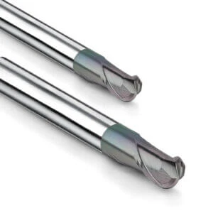
3D Surfaces and Complex Electrode Machining: How to Correctly Apply Ball-Nose Milling Cutters
Shaping complex 3D surfaces and deep cavities for EDM electrodes is a massive bottleneck in mold manufacturing. Standard flat end mills are useless for contouring intricate flow channels or towering rib electrodes. Machinists must rely on a high-precision milling cutter ball nose for continuous plunge milling, copying, and multi-axis finishing. However, as the ball-nose diameter approaches the center apex, its cutting speed drops to zero, which easily causes severe step-over marks on gummy copper.
Achieving a flawless surface finish requires exceptional corner radius precision, razor-sharp center edges, and smart CAM toolpath strategies. We always advise our Western clients to avoid driving the ball nose perpendicular to the workpiece. Instead, utilizing a fixed tilt lead angle during 5-axis machining or running contour-following paths keeps the cut away from the dead-center apex where evacuation is poorest. In 3D copper milling, superior tool geometry and scientific toolpaths are two sides of the same coin.
Preventing Chipping at Sharp Corners: Utilizing High-Quality Ball-Nose Cutters to Maintain Tight Tolerances in Thin-Walled Heat Sink and EDM Electrode Machining
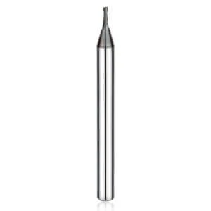
A German communication firm faced total failure milling pure copper heat sink electrodes with a 0.2 mm wall thickness and a 15:1 aspect ratio. Their off-the-shelf cutters suffered micro-chipping at the sharp ball tip due to unbalanced cutting stresses. This either tore the delicate copper walls or drifted the critical EDM spark gap out of tolerance. We solved this nightmare by deploying our specialized “Arc Series” end mill for copper, featuring cutting edges treated for micro-stress relief.
Thin-walled copper components easily deflect in sync with the tool because the material is so soft. Extreme finishing requires a tool that perfectly balances edge sharpness with impact toughness. We manufacture these cutters with an ultra-long polished land design, allowing the tool to peel away copper layers gently without exerting lateral pushing forces. This geometric refinement helped our client hold tight tolerances within 0.005 mm and completely eliminated dimensional scrap.
Runout Control: How We Help Western Clients Extend Ball-Nose End Mill Lifespan Through High-Precision Toolholding
Excessively short tool life and severe surface chatter often stem from a hidden blind spot: radial runout after tool clamping. Many operators source a premium china end mill milling cutter but carelessly mount it into a worn-out standard collet or side-lock holder. When a 2 mm ball nose spins at high speeds, a spindle-nose runout error exceeding 0.01 mm doubles or triples the load on a single cutting edge, accelerating abnormal wear and severe chip welding.
We always advise our clients to measure system runout with a dial indicator and dump traditional ER spring collets for high-precision hydraulic or shrink-fit holders. Keeping radial runout strictly under 3 microns ensures both cutting edges share the load perfectly. Copper chips then evacuate from the mirror-polished flutes in a uniform, alternating rhythm that slashes frictional heat. This hardware optimization eliminates blend lines on contoured surfaces and multiplies tool lifespan.
Shedding the “Low-End” Label: A Technical Assessment of a High-Quality China End Mill Manufacturer
Many Western shop supervisors feel apprehensive about using Chinese cutting tools due to past experiences with low-cost, inconsistent “workshop-style” products. However, top-tier manufacturers have fundamentally transformed. Today, a competitive china end mill milling cutter factory succeeds not on cheap labor, but by investing heavily in materials science, 5-axis grinding, and micron-level quality control.
To evaluate a manufacturer’s true technical depth for copper machining, look directly at their process data rather than sales pitches. Precision copper milling amplifies the slightest geometric asymmetry or micro-chipping. High-quality manufacturers gladly share raw material non-destructive testing reports and automated tool-setting data to prove their capability and earn the respect of technical peers.
The Truth About Rod Stock and Equipment: How We Utilize Virgin Ultra-Fine-Grain Tungsten Carbide and 5-Axis Grinding Machines to Ensure Razor-Sharp Cutting Edges
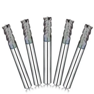
Machining sticky, work-hardening pure copper demands high-purity substrates, meaning we strictly avoid recycled materials. We utilize virgin tungsten carbide with a submicron grain size under 0.4 μm for every specialized end mill for copper. This material provides the perfect blend of extreme hardness and high modulus of rupture, allowing us to grind razor-sharp cutting edges without sacrificing structural integrity.
Premium substrates require world-class grinding execution. We produce our high-end cutters using fully automated, 5-axis CNC grinding centers from industry leaders like Walter and ANCA. Equipped with thermal compensation and ultra-fine diamond wheels, these machines grind aggressive rake angles and mirror-polished flutes in a single setup. Under 150x magnification, our edges remain perfectly silky and serration-free.
Evaluation Criteria for Western B2B Clients: Why Seasoned Buyers No Longer Focus Solely on Unit Price, but on the Comprehensive Tooling Cost Per Copper Part
Experienced procurement professionals look beyond the initial unit price and focus on the comprehensive Cost Per Part. Cheap standard cutters often fail after fewer than 10 parts due to severe chip welding, forcing frequent stoppages. Even worse, unexpected tool breakage can instantly scrap high-value, semi-finished copper workpieces, wiping out any upfront tool savings.
As a dedicated carbide end mill supplier, we focus on total lifecycle value. Our custom-engineered tools match your specific machine rigidity and spindle speeds, yielding over 30 parts per tool without manual intervention. By maintaining a stable 99.8% yield rate, our cutters reduce machine downtime and material waste, delivering a much higher return on investment than cheap alternatives.
Avoid Blind Trial-and-Error: How to Identify a Carbide End Mill Supplier That Offers On-Site Technical Support
When line failures happen, many shops blindly test random tool samples, turning their production floors into expensive laboratories. Because copper features a massive thermal expansion coefficient and high stickiness, a universal standard tool does not exist. If your carbide end mill supplier only sells out of a catalog without understanding your application, you bear the financial burden of lost production time.
A qualified tool partner must have real workshop machining experience. Assess whether your supplier can quickly troubleshoot your specific spindle limits, feed rates, and coolant pressures. If you face bottlenecks milling difficult copper parts, demand a supplier that provides in-depth technical application engineering rather than a simple price sheet.
How We Customized a Non-Standard Rake Angle Solution Based on a Western Client’s Machine Rigidity
An Italian automotive supplier struggled with severe tool wear while milling pure copper busbars on an older machining center. The machine had a large physical envelope but lower spindle rigidity, causing our standard 15° high-rake carbide end mill cutter tools to chatter under cyclical cutting forces. The tool flank faces flaked and failed after fewer than five parts, leaving the client frustrated.
Our engineering team analyzed their setup video and machine dynamics, then developed a modified, non-standard solution. We dropped the rake angle slightly to 12° to stabilize the cutting force and implemented an asymmetrical, unequal index flute distribution to disrupt harmonic resonance. This micro-customization allowed the client to run thousands of parts smoothly without purchasing a new machine.
A Guide to Avoiding Pitfalls: A Competent Carbide Milling Cutter Supplier Sells Solutions—Not Just Standard Products
Selecting a copper cutter is ultimately about buying a proven chip evacuation solution. Whether you run a high-feed indexing mill or a precise milling cutter ball nose for 3D contouring, every geometric angle and polished surface must work to eject gummy chips instantly. If a manufacturer cannot explain their tool geometry through chip fluid dynamics, they cannot solve your problem.
Every shop operates with different rigidity, cooling, and CAM programming. If you are struggling with heavy burrs or short tool life on oxygen-free copper, beryllium copper, or tellurium copper, feel free to share your blueprints, material grades, and cutting conditions with us. We talk engineer-to-engineer to optimize your parameters and stop tool sticking before you press start.


