


Last week, a long-standing client from Ohio sent us an urgent email. They were racing against the clock to machine a batch of alloy steel molds on a 3-axis machining center. They used standard, off-the-shelf ball nose milling cutters, but the tools kept failing. By the third cavity, the tip inevitably micro-chipped, leaving nasty score marks across the finished workpiece surface.
This scenario is all too familiar to us. Over the past 15 years, our team has dedicated itself to the R&D and manufacturing of CNC milling cutters rated up to HRC55. While providing technical support across North America, we hear the same complaint weekly: “Why are my tools failing so fast when my spindle speeds and feeds match the catalog exactly?”
Here is the truth: many industry peers are trapped in a classic textbook blind spot. Hardened steels possess immense thermal strength and work-hardening characteristics, making them highly sensitive to sudden fluctuations in cutting forces. Furthermore, when running a ball nose milling cutter on 3D profiles, the tool geometry presents a built-in, fatal flaw: the closer you get to the center tip, the closer your actual cutting speed (Vc) approaches zero.
Think about what that means in reality. If you blindly apply standard formulas to your programming, your tool tip isn’t actually “cutting” the steel. Instead, it is brutally scraping and extruding the material under extreme pressure. This creates an immediate buildup of friction heat, triggers massive radial runout, and ultimately causes catastrophic tool failure.
To solve these stubborn setup issues, you cannot rely on generic, standard catalogs. In many instances, we must engineer a custom milling cutter with optimized geometries. We back this up with a highly specific speed and feed compensation strategy tailored to the client’s machine rigidity, work-holding setups, and CAM dynamic toolpaths. Optimizing these parameters is a precise balancing act between feed per tooth (fz), effective cutting diameter, and heat evacuation.
Does this sound like your typical week? You invest heavily in premium solid carbide tools, yet during critical finishing passes, you are still left guessing. Unsure of how the tool behaves at high RPMs, you end up hovering anxiously over the feed-hold button, just hoping for the best.
Say Goodbye to Tool Breakage: How We Help Our Western Clients Fine-Tune Core Cutting Parameters for CNC Milling Cutters
In our interactions with shop supervisors across North America, we find their biggest headache isn’t bulk roughing. The real stress lies in finishing, where a cnc milling cutter must run stably for dozens of hours without a single mishap. A slight parameter mismatch causes surface ripples or snaps the tool deep inside a cavity, scrapping hours of precision work.
To eliminate tool breakage, look past static handbook values and focus entirely on the dynamic forces acting on the edge at the exact moment of engagement. Real-world shop floors introduce complex variables like spindle runout, thermal displacement, and coolant angles. True optimization means adjusting parameters based on acoustic feedback and chip morphology to balance metal removal rates with thermal fatigue.
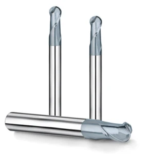
Why Blindly Applying Handbook Parameters Leads to Rapid Chipping in Ball Nose Milling Cutters
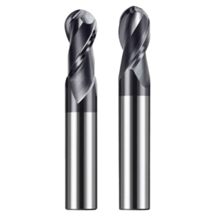
Many junior CAM programmers simply copy-paste the speeds and feeds from a catalog chart directly into their software. The result, all too often, is that the ball nose milling cutter develops micro-chipping along its cutting edge within minutes. Catalog data assumes pristine laboratory conditions with zero spindle runout, minimal tool overhang, and maximum clamping rigidity.
We recently resolved this for a British client experiencing severe peripheral edge chipping while profiling heat-treated mold steel. Excessive tool overhang was inducing minute radial runout—a physical elastic deformation that standard handbook formulas fail to account for. Reducing the standard feed rate by 20% and switching to a trochoidal milling path to maintain a constant radial depth of cut (ae) immediately stopped the chipping.
Distinguishing Effective Cutting Speed From Spindle Speed: The “Zero Linear Velocity” Trap at the Ball-Nose Tip—and How to Avoid It
Your CNC inputs RPM based on the tool’s nominal outer diameter, but 3D finishing often occurs near the bottom apex where the working diameter is tiny. Consequently, your effective cutting speed (Ve) plummets to absolute zero at the dead center of the ball nose milling cutter. This zero linear velocity trap drives intense heat spikes, causing the tool to plow through steel instead of shearing it cleanly.
To defeat this engineering bottleneck, avoid attacking flat or sloped surfaces with a purely vertical tool axis. By tilting the spindle or worktable 15 to 20 degrees, you shift the engagement point completely out of the dead zone and onto the high-velocity side flutes. For a fixed 3-axis setup, manually scale up your RPMs to compensate for the smaller effective diameter and use air or lubrication to evacuate heat.
Bidding Farewell to Broken Tools: How We Help Western Clients Fine-Tune Core Cutting Parameters for CNC Milling Cutters
In our interactions with shop supervisors across North America, we find their biggest headache isn’t bulk roughing. The real stress lies in finishing, where a cnc milling cutter must run stably for dozens of hours without a single mishap. A slight parameter mismatch causes surface ripples or snaps the tool deep inside a cavity, scrapping hours of precision work.
To eliminate tool breakage, look past static handbook values and focus entirely on the dynamic forces acting on the edge at the exact moment of engagement. Real-world shop floors introduce complex variables like spindle runout, thermal displacement, and coolant angles. True optimization means adjusting parameters based on acoustic feedback and chip morphology to balance metal removal rates with thermal fatigue.
Why Blindly Applying Tool Catalog Parameters Leads to Rapid Chipping in Ball Nose Milling Cutters
Many junior CAM programmers simply copy-paste the speeds and feeds from a catalog chart directly into their software. The result, all too often, is that the ball nose milling cutter develops micro-chipping along its cutting edge within minutes. Catalog data assumes pristine laboratory conditions with zero spindle runout, minimal tool overhang, and maximum clamping rigidity.
We recently resolved this for a British client experiencing severe peripheral edge chipping while profiling heat-treated mold steel. Excessive tool overhang was inducing minute radial runout—a physical elastic deformation that standard handbook formulas fail to account for. Reducing the standard feed rate by 20% and switching to a trochoidal milling path to maintain a constant radial depth of cut (ae) immediately stopped the chipping.
Distinguishing Between Effective Cutting Speed and Spindle RPM: The “Zero Linear Velocity” Trap at the Ball-Nose Tip—and How to Avoid It
Your CNC inputs RPM based on the tool’s nominal outer diameter, but 3D finishing often occurs near the bottom apex where the working diameter is tiny. Consequently, your effective cutting speed (Ve) plummets to absolute zero at the dead center of the ball nose milling cutter. This zero linear velocity trap drives intense heat spikes, causing the tool to plow through steel instead of shearing it cleanly.
To defeat this engineering bottleneck, avoid attacking flat or sloped surfaces with a purely vertical tool axis. By tilting the spindle or worktable 15 to 20 degrees, you shift the engagement point completely out of the dead zone and onto the high-velocity side flutes. For a fixed 3-axis setup, manually scale up your RPMs to compensate for the smaller effective diameter and use air or lubrication to evacuate heat.
Step-over and Feed Compensation for Ball Nose Milling Cutters in 3D Surface Finishing
In mold manufacturing and complex surface machining, the finishing stage accounts for a significant portion of total cycle time. When programming toolpaths for a ball nose milling cutter, the interplay between step-over distance and feed rate directly determines final surface quality and manual polishing costs. Setting a fixed step-over on complex profiles leads to unstable metal removal rates and dangerous tool shock.
In our workshops, especially when machining regions with severe curvature variations, we employ an “adaptive feed” control logic. Gaining a deep understanding of the contact arc length allows us to identify the optimal balance between geometric parameters and the machine’s dynamic response. This precise compensation technique maximizes the efficiency of every single toolpath when finishing complex steel mold components.
How We Precisely Back-Calculate Feed Rates for 3-Axis/5-Axis Machines Based on Residual Height
To achieve the micron-level surface roughness our North American clients demand, our primary focus must be on the residual height. While engineering drawings establish our target theoretical scallop height, true simultaneous multi-axis cutting requires this value to undergo a secondary compensation adjustment based on real-time feed rates to protect the ball nose milling cutter.
Last month, we assisted a Canadian automotive mold manufacturer whose machine experienced minute thermal shocks because a rigid 0.05 mm step-over forced frequent mid-pass deceleration. We introduced a geometry compensation model that allowed them to safely increase the step-over to 0.12 mm. By automatically adjusting the feed rate based on the surface inclination angle, we cut the total machining cycle by nearly 40%.
Trochoidal Milling and Dynamic Toolpath Strategies: How Small Radial Depths of Cut Can Unleash the High-Feed Potential of CNC Milling Cutters
In traditional profiling, the cutter’s arc of engagement spikes abruptly at sharp corners, forcing operators to lower the overall feed rate to protect the tool. To overcome this bottleneck, we actively champion trochoidal milling and dynamic toolpaths. By pairing a small radial depth of cut (ae) with a deep axial cut (ap), a high-rigidity cnc milling cutter maintains constant cutting forces throughout the entire path.
This minuscule radial engagement triggers a physical phenomenon known as chip thinning, meaning the actual chip thickness is significantly thinner than the programmed feed per tooth. We capitalize on this trait to boldly increase the overall feed rate to levels 3 to 5 times higher than conventional methods. This high-speed, low-load approach rapidly evacuates heat and fully unlocks the rigidity potential of solid carbide tools.
Machining Challenges With Steel Workpieces That Standard Tools Cannot Solve: When to Consider Custom Milling Cutters
In our 16 years of tool manufacturing, we have learned that standard catalog tools possess inherent physical limitations. When Western workshops face deep cavities or tight gaps in tough mold steels, relying on standard tools leads to a dead end. Rigidity losses, workpiece interference, and poor chip evacuation will quickly bring your automated production lines to a grinding halt.
Our team always runs a strict cost-benefit analysis before altering a setup. If switching to a specialized custom milling cutter consolidates three operations into one or eliminates hand-polishing blend lines, it isn’t a budget drain. It is a direct investment that unlocks higher net profits by maximizing the output of your multi-axis CNC machinery.
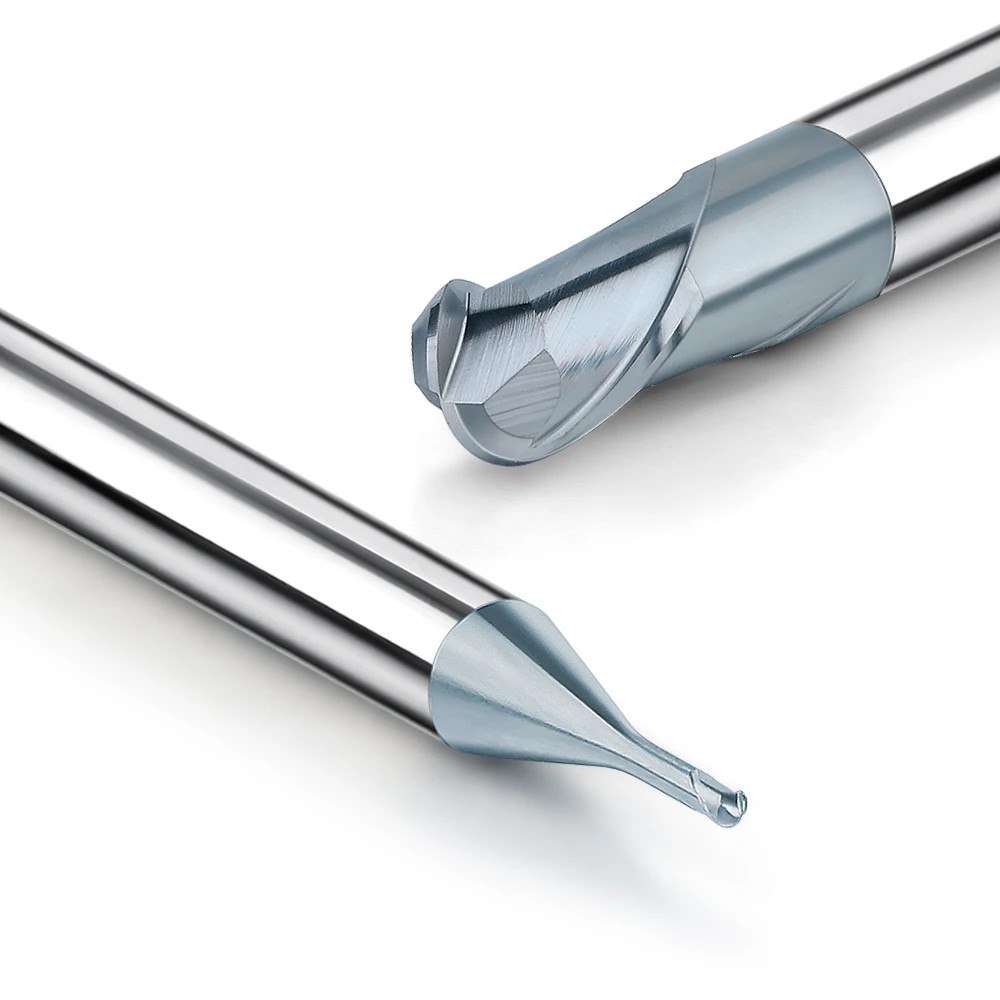
Custom Non-Standard Ball Nose Milling Cutters: Optimizing Neck Diameter and Vibration-Damping Design for Machining Deep Cavities
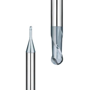
Deep cavities and tall ribs in hardened tool steels are notorious for inducing severe machining vibrations. When your tool reach exceeds five times the cutting diameter, tiny radial forces amplify into massive tool deflection. We recently helped a US shop milling a 120mm narrow slot in an automotive mold where a standard ball nose milling cutter suffered high-pitched chatter and ruined the surface finish.
Instead of changing the tool holder, we engineered a custom solid carbide tool featuring a micro-tapered, reinforced neck. This geometric modification doubled the neck rigidity without creating workpiece interference. We also added a microscopic chamfered relief at the neck transition, which eliminated the conical friction contact that triggers resonance and successfully wiped out all surface “water ripple” defects.
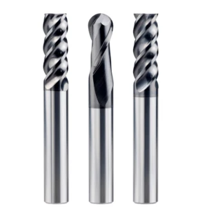
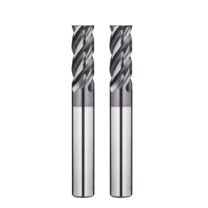
Case Study: Optimizing Cutting Parameters for Custom Variable-Helix End Mills in High-Volume Production
For high-volume manufacturers running round-the-clock automotive or hydraulic lines, saving a single second per part saves thousands of dollars. When machining tough alloy steel forgings, uniform tool engagement creates periodic harmonic resonance that rapidly chips the tool’s flank face. We saw this with a European OEM whose standard four-flute cnc milling cutter failed prematurely due to constant mechanical shock frequencies during side milling.
To break this resonance loop, we developed a non-standard end mill featuring an asymmetrical, unequal-pitch geometry and a variable helix angle. By shifting the flute indexing away from 90 degrees and varying the helix from 38 to 41 degrees, we disrupted the rhythmic impact against the steel workpiece. This allowed the client to boost their feed per tooth by 45% while slashing spindle noise in half.
A Checklist for Fine-Tuning Steel Ball Nose End Milling Cutters Based on On-Site Clues
The most sophisticated CNC machining techniques are never static; they live within the actual acoustics and environment of your shop floor. When profiling tough alloy steels, complex real-world variables will always bypass your CAM simulation. That is why we teach programmers to execute millimeter-level parameter tweaks by reading subtle visual and auditory clues directly from the machine.
This real-time diagnostic capacity is what separates a successful weekend of unattended, lights-out machining from a catastrophic tool smash. We have distilled our years of field experience solving tool failure across North America into a two-part checklist. If you are battling erratic tool life, cross-reference your current ball milling cutter for cutting steel setups against these indicators.
Diagnosing Chatter by Sound: How to Avoid Resonance Frequencies in Steel Machining Through RPM Fine-Tuning
Experienced machinists can instantly evaluate a cut simply by listening to the spindle sound. A smooth, dull hum represents an ideal cut, while a sharp, piercing metallic screech indicates severe system resonance. If your ball nose milling cutter screeches during shallow finishing, dropping the feed rate is counterproductive; the reduced chip load causes the tool to rub, accelerating edge chipping.
Instead, interrupt the resonant equilibrium right at the control board by adjusting your spindle RPM in 3%$ to 5% increments. Often, a quick bump upward by 200 RPM or a drop of 150 RPM alters the impact frequency enough to silence the chatter instantly. If you are trapped in a deep-cavity screech, send us your part drawings and fixture layout so we can analyze your specific system harmonics.
Reading Tool Life from Chips: Judging Feed Rates by Chip Color and Morphology
Metal chips provide a live diagnostic report from your machine’s enclosure. When profiling steel, the majority of the generated heat must evacuate inside the chip. If your scattered chips are a dark, oxidized blue or black with rough, fused edges, your feed per tooth is too low or your speed is too high. Heat is baking into your cnc hrc55 milling cutter tools, rapidly degrading the carbide.
Conversely, thick, jagged, saw-toothed chips mean your feed rate is overloading the cutting edge, causing microscopic flank flaking. Ideally, steel chips should retain a clean silver-gray, pale straw, or light purple hue with uniform curl shapes. If you are dialing in a high-volume aerospace alloy and your chips look spent, share your material specs with us so we can optimize your edge geometry.


