Over the past decade, we have often encountered customers complaining about short tool life, unstable machined surfaces, or recurring dimensional deviations in deep cavity mold projects. Whether working with high-hardness mold steel or complex-profile deep-cavity aluminum alloys, we’ve found that selecting the right types of end mills is not just about following manual recommendations. It requires careful consideration of the specific cavity shape, cutting length, and material allowance strategy.
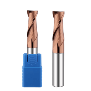
For example, during roughing, using standard flat end mills often leads to poor chip evacuation and significant sidewall vibration. Through repeated practical verification, we’ve found that a wavy edge design and the proper number of cutting edges on a roughing end mill significantly reduce these issues, enabling safe removal of large amounts of material. In finishing, many clients prefer short-edged end mills for deep cavity sidewall finishing. However, we’ve observed that tool length, cutting edge geometry, and coating selection of finishing end mills have a decisive impact on surface finish and dimensional stability, particularly in mold steel cavities above HRC45. Using incorrect tool combinations often results in repeated rework.
In our projects, we frequently communicate with carbide end mill suppliers to ensure consistent tool hardness and cutting edge geometry within the same batch, avoiding fluctuations that could impact machining cycles. Years of experience have taught us that deep cavity machining success relies not solely on tool selection but on a combination of tool type, cutting edge design, cutting parameters, and clamping methods.
Faced with these recurring deep cavity challenges, we always ask ourselves: How can we choose a tool combination that guarantees surface quality, extends tool life, and reduces rework?
At What Stage Do Most Tool Failures Occur in Deep Cavity Machining?
In our experience, every stage of deep cavity machining presents unique challenges. Tool failure is rarely sudden; it typically results from gradual accumulation of stress or wear. Sidewall oscillation and poor chip removal often occur during roughing, while excessive tool overhang in semi-finishing frequently causes dimensional drift. In finishing, surface textures are often mistakenly blamed on spindle vibration or machine tool precision, when in reality improper tool geometry or cutting edge selection is usually the culprit. Recognizing typical problems at each stage allows us to anticipate risks and adjust tool combinations and cutting strategies early in the process.
We analyze deep cavities by dividing them into roughing, semi-finishing, and finishing zones, making trade-offs based on actual cutting conditions and material hardness. For mold steel deep cavities, factors such as cutting edge length, tool diameter, tip radius, coating type, and tool holder rigidity all affect final results. By analyzing past project data, we’ve found that rational tool arrangement and cutting parameter selection significantly reduce the risk of tool breakage and dimensional deviations.
Poor Chip Removal and Sidewall Vibration in the Roughing Stage
During roughing, we typically use long-flute or large-diameter roughing end mills to remove material quickly. However, if the tooth profile is poorly designed or the feed is not optimized for deep cavity sidewalls, chip evacuation issues quickly arise. Even within the same material batch, cutting conditions vary in different cavity locations. While wavy and multi-edged roughing end mills improve chip breaking, we still balance their use with depth of cut and feed rate. On-site observation of chip shape, cutting sound, and tool temperature helps us decide whether to reduce per-tooth depth or adjust feed.
Sidewall vibration is another recurring problem. Long-overhang tools, even in rigid machines, can wobble slightly, causing dimensional drift or surface micro-ripples. We typically adjust tool diameter or employ multi-step feed strategies to maintain uniform cutting forces while preserving tool life. Experience shows that roughing stability directly impacts semi-finishing and finishing quality; poor roughing is almost impossible to fully correct later.
Excessive Tool Overhang in Semi-Finishing Causes Dimensional Drift
Semi-finishing involves medium-diameter tools to refine contours. Deep cavities often increase tool overhang, and insufficient rigidity causes slight bending, resulting in dimensional drift. We’ve found that even with high-precision machines, overhang ratios exceeding 3:1 or 4:1 can lead to tens of micrometers of sidewall deviation. To control deflection, we proactively choose shorter cutting edges, stiffer tools, and reduce per-tooth material removal. Monitoring machining temperature and chip morphology helps us assess tool stability in real time.
Tool selection and cutting strategy are critical. We discuss with clients whether multiple passes or adjusted tool profiles are necessary to balance efficiency and accuracy. Tool holder clamping length, coolant flow, and sidewall allowance all significantly affect final dimensions. Semi-finishing is not just “removing excess material”; it lays the foundation for finishing. Ignoring overhang rigidity often leads to rework.
Surface Textures in Finishing Are Often Tool Selection Issues
In finishing, customers often blame visible textures on spindle or machine accuracy. In our experience, improper finishing end mill selection is usually the root cause. Long-neck tools often produce chatter in deep cavities, while too many cutting edges increase heat, reducing surface quality. We eliminate surface textures by adjusting tool shape, cutting edge number, and optimizing cutting parameters, not just upgrading the machine.
Tool coating and material greatly affect finishing. For high-hardness mold steel, we confirm grinding accuracy and coating uniformity with carbide end mill suppliers. Even with perfect machines, incorrect tool combinations can cause uneven textures or minor dimensional deviations. Evaluating tool geometry, cutting edge length, and coating before finishing ensures stable machining and quality surfaces.
How We Differentiate Types of End Mills in Deep Cavity Machining
Different tools behave differently depending on cavity shape, depth, allowance, and material hardness. We don’t rely solely on manuals but combine machine rigidity, tool overhang, and coolant flow to determine the optimal tool for each area. Years of experience have allowed us to develop a rapid assessment method based on cutting edge type, tool length, and number of edges, preventing machining deviations and chatter during process planning.
We frequently discuss tool combinations with clients. Deep cavity machining is never single-tool; it requires coordinated use of roughing, semi-finishing, and finishing end mills. We track tool life, cutting load, and chip evacuation, adjusting selection and parameters based on data. This reduces breakage risk and stabilizes results, especially in mold steel or high-hardness cavities, where every detail of tool selection affects final surface finish and dimensional accuracy.
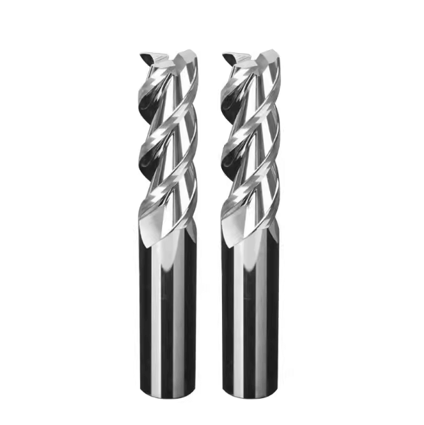
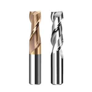
Long-Flute Flat End Mills for Roughing Large Sidewall Allowances
We use long-flute flat end mills for roughing large sidewall allowances. The long-flute design reduces cuts while maintaining depth of cut, shortening cycles. Tool rigidity is crucial; excessive overhang or insufficient clamping can cause micro-vibrations and sidewall deviations. We balance tool holder clamping, feed, and depth of cut for efficiency and tool longevity.
Chip morphology is closely monitored. Long flat cutters can clog, increasing temperature and vibration. Adjusting per-tooth feed or using layered cuts based on cavity width, depth, and material hardness ensures roughing stability. While more steps are required, this approach minimizes rework in semi-finishing and makes tool life predictable.
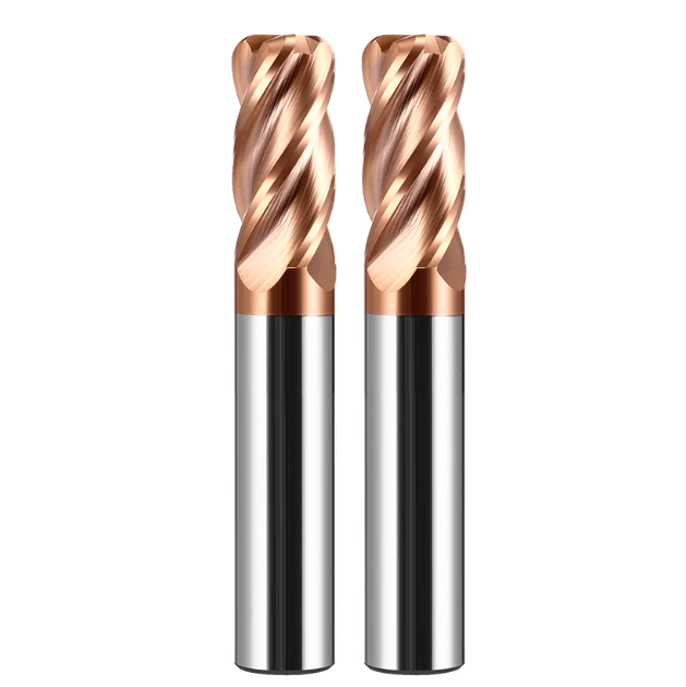
Round Nose Cutters in Deep Cavity Corner Areas
Round nose cutters distribute cutting stress in corners, preventing sharp-angle vibration and cutting edge overload. In mold steel deep cavities, improper tool selection can cause micro-cracks or indentations. We choose a suitable radius for the cavity depth to maintain uniform cutting force and reduce anomalies.
Tool diameter and edge length impact stability. Even round nose cutters with long overhangs can vibrate. Adjusting clamping length and cutting parameters ensures rigidity limits are not exceeded while maintaining surface finish and dimensional consistency.
Ball End Mills for Bottom Contour Transitions
Ball end mills are preferred for deep cavity bottoms and complex contours. They allow smooth toolpath transitions, reducing tool marks and ripples. Flat or round nose end mills often leave noticeable marks on curved surfaces in semi-finishing or finishing.
We control cutting load according to tool diameter and edge length. Long overhang and concentrated forces at the bottom can cause micro-vibrations or tip wear. Pre-assessing cutting path, per-tooth feed, and coolant flow optimizes chip removal. Practical trials show this combination reduces bottom tool marks, extends tool life, and improves predictability when reporting results to clients.

Why is a Roughing End Mill More Stable Than a Conventional Flat End Tool in Deep Cavity Roughing?
In our extensive experience with deep cavity machining, the roughing stage is the most prone to tool failure and sidewall vibration. Conventional flat end tools tend to cause chip buildup, uneven cutting forces, and micro-vibrations when overhanging excessively while cutting large allowances. Through repeated experiments and customer case studies, we have observed that the tooth profile and wavy edge design of roughing end mills effectively distribute cutting forces and improve chip removal efficiency. This results in significantly enhanced machining stability and extended tool life. When selecting tools, we consider tool rigidity, cutting edge length, diameter, and depth of cut simultaneously to maximize roughing robustness.
Furthermore, cutting strategy during roughing directly impacts subsequent semi-finishing and finishing stages. Using an inappropriate tool can cause sidewall vibration or chip accumulation, leading to cavity shape deviations, increased tool wear, and higher rework risk. We select roughing end mills with wavy edge designs appropriate for cavity width, depth, and material hardness. Cutting parameters and coolant flow are optimized to maintain stable chip evacuation and temperature control throughout the roughing process.
The Actual Impact of Wavy Edge Design on Chip Breaking
Chip morphology significantly affects tool life and stability in deep cavity roughing. With standard flat tools, chips are long and thin, prone to entanglement and uneven cutting forces. Wavy edge roughing end mills break chips into shorter segments, reducing removal difficulty and minimizing tool tip impact caused by swirling chips. By observing chip formation and cutting sounds on-site, we adjust feed rates or depth of cut in real time.
The wavy edge design is particularly crucial for high-hardness steel. In mold steel or HRC45+ materials, an unsuitable tooth profile concentrates cutting forces at the tip, accelerating wear and risk of breakage. Practical trials show that using wavy-edged roughing end mills improves chip breaking, reduces tool tip load, and allows smoother semi-finishing with fewer passes.
How Tooth Profile Affects Tool Life During Heat Accumulation
Prolonged cutting in deep cavities generates heat at the cutting edge. Ordinary flat tools struggle to dissipate heat under high loads, accelerating tip wear and risk of breakage. Roughing end mills with specialized tooth profiles and wavy edges improve the cutting contact angle, facilitating rapid chip evacuation. This lowers local temperature and extends tool life.
We also adjust cutting parameters according to cavity depth and material hardness. For high-hardness mold steel, if heat builds too quickly, we reduce feed per tooth or increase coolant flow to prevent excessive wear. Experience shows that selecting the right tooth profile is essential for thermal management, balanced cutting forces, and reduced vibration.
When to Prioritize Lateral Depth of Cut Over High Feed Rates
In deep cavity roughing, balancing efficiency and tool stability is crucial. While higher feed rates theoretically reduce machining time, long-overhang tools cutting large allowances often vibrate at high feed. We prioritize controlling lateral depth of cut based on cavity depth and overhang ratio, keeping cutting forces within the tool’s rigidity limits. Although individual cuts are shallower, overall machining is more stable, with reduced tool wear.
Controlling lateral depth also improves chip removal and heat distribution. Excessive feed causes chip accumulation and localized heat spikes, while smaller lateral cuts enable smoother evacuation and lower tip load. We frequently explain to clients that reducing feed rate is not efficiency loss but a strategy to ensure controllable, stable roughing and provide a solid foundation for subsequent semi-finishing and finishing stages.

Practical Experience in Selecting Finishing End Mills for Deep Cavity Sidewall Finishing
In our long-term experience handling deep cavity mold finishing projects for clients, sidewall finish and dimensional accuracy are often more prone to problems than bottom machining. Tool geometry, cutting edge count, edge length, and tool holder clamping significantly impact the stability of deep cavity machining. Machine tool accuracy or high-speed rotation alone cannot guarantee quality. Correctly selecting finishing end mills and optimizing cutting parameters is key to preventing chatter marks, ripples, and poor surface finish. Before each operation, we evaluate cavity depth, width, material hardness, and tool overhang to select the most suitable tool combination.
Cutting fluid flow direction and tool path also affect heat accumulation and chip buildup. Finishing immediately after semi-finishing deep cavities without sufficient rigidity or correct tool selection can leave micro-vibration marks. Years of observation have shown that even the same type of tool behaves differently under varying overhangs and cutting conditions. Therefore, we emphasize practical experience over theoretical parameters for tool selection and path planning.
Difference Between 4-Flute and 2-Flute Tools in Deep Cavity Sidewall Finishing
We frequently compare 4-flute and 2-flute tools in deep cavity sidewall finishing. Four-flute tools provide smoother cutting force distribution and generally better surface finish. However, in deep cavities with long overhangs, multiple flutes can increase rigidity load, leading to vibration marks. For deep or narrow cavities, we often select 2-flute tools. This sacrifices some cutting efficiency but reduces vibration and surface ripples.
We also optimize feed per tooth and cutting direction in conjunction with tool path. Even a 2-flute tool can produce ripples if feed is excessive or the path is staggered incorrectly. Feed adjustments are based on cavity width, depth, and material hardness, combined with cutting fluid flow for smooth chip evacuation. Our experience shows that 4-flute and 2-flute tools each have trade-offs, and selection depends on overhang, surface finish, and cutting load.
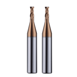
Why Long-Neck Finishing End Mills Are More Prone to Chatter
Long-neck tools reach deep cavities but excessive overhang reduces rigidity, making chatter marks likely. This is especially true for high-hardness steel or deep sidewalls. Slight tip wobble can leave periodic surface marks. We mitigate this by shortening cutting length, increasing tool holder length, and adjusting feed per tooth and cutting speed to maintain stability.
Tool edge profile and coating also matter. High-hardness material wears long-neck tools quickly. Without timely replacement or parameter adjustment, chatter marks increase. We dynamically adapt cutting strategy based on tool wear and overhang, ensuring cavity depth requirements are met while minimizing chatter.
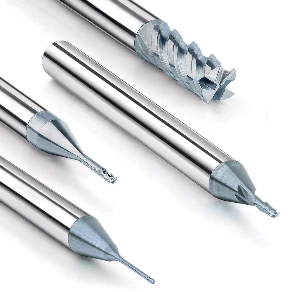
Small Radius Angles Significantly Affect Surface Quality
Many customers focus only on diameter and cutting edges, overlooking small corner radii. Even with the right finishing end mill, a mismatched tip radius can create localized marks or micro-dimples. On-site, we adjust tool tip radius to match cavity corners and combine this with cutting fluid and parameter optimization to improve surface quality.
In HRC45+ mold steel, small radius angles affect tool load and chip removal. Proper tool tip radius improves surface finish, reduces localized cutting force, and minimizes tool tip wear, extending tool life. Before finishing, we assess cavity angle, depth, and tool geometry to make fine adjustments for stable, reliable results.

Type of End Mill for Mold Steel – Most Common Selection Errors
Incorrect tool selection is a frequent cause of rework and tool wear in deep cavity mold steel machining. Different hardness steels require distinct tool substrates, cutting edge designs, and coatings. Many customers focus only on diameter or edge count, ignoring the material’s effect on cutting load and tool life. We combine mold steel HRC, cavity depth, and machining allowance to evaluate tool rigidity and wear resistance, ensuring roughing and finishing remain controllable.
Tool overhang and clamping method also affect stability. Excessive overhang or insufficient clamping can cause vibration or surface texture defects. We simulate cutting paths and tool loads, coordinate coolant flow and chip removal, and optimize tool combinations to reduce anomalies and wear. Empirical judgment based on practical observation is more reliable than simply following specifications, reducing rework and downtime.
HRC32 vs HRC48 Mold Steels Require Different Tool Substrates
HRC32 mold steel, a medium-hardness material, requires high-toughness carbide to withstand cutting loads without breaking. HRC48, being harder, demands wear-resistant and thermally crack-resistant carbide. Substrate selection is based on actual material hardness, such as micro-grained or ultra-fine-grained carbide, reducing wear and breakage risk under high cutting forces.
On-site, we observe temperature, chip morphology, and tool performance. Even with identical profiles, different hardness steels behave differently. Feed per tooth and depth of cut are adjusted to keep cutting within hardness tolerances, maintaining sidewall and bottom dimensional accuracy.
Coating Often More Critical Than Cutting Edge in High-Hardness Steel
In HRC45+ mold steel, coating has a greater impact on tool life and surface quality than cutting edge geometry. Insufficient wear resistance or adhesion can cause rapid wear, built-up edges, or microcracks. We select wear-resistant coatings, like TiAlN or AlCrN, and adjust cutting parameters according to cavity depth.
We also ensure coating compatibility with coolant and cutting speed. Heat concentrates inside deep cavities; mismatched coating or parameters can raise tool temperature, degrade surface finish, and cause micro-vibrations or tip chipping. Tool replacement or parameter adjustment is based on observed wear and cutting noise, providing more reliable results than theoretical calculations.
Why Long Overhangs in High-Hardness Steel Require Reduced Feed per Tooth
Excessive overhang reduces rigidity, concentrating forces at the tip and causing micro-vibration marks or dimensional deviations. We reduce feed per tooth to distribute cutting forces evenly, maintaining machining stability.
Feed rate is selected on-site based on cavity width, depth, and tool diameter. While reducing feed increases machining time, it effectively controls vibration and tool wear, which is more important than maximum feed in deep cavities of HRC45+ mold steel. Experience shows that balancing overhang, cutting force, and feed is key to tool life and machining quality.
How Different Tool Lengths Affect Actual Stability in Deep Cavity Machining
In our years of experience in deep cavity machining, tool length has a greater impact on stability than many customers realize. We often see customers focus excessively on total tool length, neglecting the relationship between effective cutting area and tool rigidity. While long-edged tools can reach the bottom of deep cavities, exceeding the tool’s rigidity tolerance can easily cause vibration and sidewall ripples. We typically assess cavity depth, allowance, and cutting path before determining cutting edge length and tool holder clamping to ensure controllable machining.
Tool length also affects cutting force distribution and chip removal efficiency. In deep cavities, long overhanging tools concentrate load at the tip, hindering chip evacuation and exacerbating vibration and wear. By observing chip morphology and surface texture, we determine whether to shorten cutting edge length or adjust cutting parameters. Years of experience show that controlling effective cutting length, rather than simply using the longest possible tool, ensures better stability and surface quality.
Longer Cutting Edge Length Isn’t Always Better; Consider the Effective Cutting Area
Excessively long cutting edges often reduce tool rigidity, generating micro-vibrations and ripples on sidewalls or bottom surfaces. We calculate the truly necessary effective cutting area based on cavity depth and cutting allowance, selecting a cutting edge length that meets machining requirements without compromising rigidity.
We also consider tool diameter and overhang ratio when planning cutting strategies. Excessive feed or unreasonable cutting angles with long edges can increase tool tip load. By simulating the cutting path and monitoring cutting forces on-site, we optimize feed per tooth and depth of cut, maintaining rigidity and improving surface finish.
Increased Overall Tool Length Impacts Spindle Load More Than Expected
Customers often underestimate the effect of longer tools on spindle load. In deep cavity machining, longer tools transmit more vibration and torque to the spindle, causing significant load variations even with sufficient machine power. We calculate spindle load variations in advance and adjust cutting parameters based on cavity depth and tool length to prevent excessive vibration or tool breakage.
Longer tools also generate higher localized temperatures and faster tip wear when cutting high-hardness mold steel. Without reducing feed per tooth or optimizing coolant flow, tool life shortens considerably. We dynamically adjust cutting strategy using cutting force monitoring and tool wear records to maintain stability and reduce rework risk.
Tool Holder Length Often Determines Final Machining Results
Tool holder length directly affects stability. Even with reasonable cutting edge length, insufficient clamping causes wobble when cutting sidewalls or bottom, resulting in dimensional deviations and chatter marks. We typically clamp at least two-thirds of the effective cutting area and adjust cutting load to guarantee stability.
Clamping methods are adjusted according to cavity depth and tool diameter. Insufficient clamping on long-edged tools concentrates forces at the tip, accelerating wear and causing chipping. We assess clamping adequacy by observing cutting sounds, chip morphology, and surface texture, adjusting clamping and cutting parameters as needed.

Tool Combinations We Commonly Use for Deep Cavity Milling for European and American Clients
In years of deep cavity milling projects for European and American clients, we have observed that using a single tool often compromises stability and surface quality. We typically develop a phased tool combination strategy based on cavity depth, allowance, and material hardness.
First, a roughing end mill removes excess material, ensuring efficient roughing and balanced cutting forces. Then, during semi-finishing or finishing, a finishing end mill completes the sidewalls and bottom, achieving high-quality surface finish and dimensional accuracy. This staged approach significantly reduces vibration, tool wear, and rework rates.
On-site, we adjust tool diameter, number of cutting edges, and cutting edge length for each stage according to cavity shape and depth. Even tools of the same model perform differently under varying overhang lengths and cutting paths. Empirical observation of cutting forces, chip removal, and cutting temperature ensures maximum tool life and machining stability.
Roughing First, Then Finishing
In practice, we almost always start with a roughing end mill. This provides balanced cutting forces, smooth chip removal, and minimizes tool overhang vibration. Tool diameter and tooth profile are selected based on cavity depth and material hardness to ensure stable roughing.
A finishing end mill then completes the sidewalls and bottom, guaranteeing surface finish and dimensional accuracy. This staged tooling strategy is more reliable than a single-cut approach, particularly for deep cavities in high-hardness mold steel.
Allowance after roughing is critical. Insufficient analysis of cavity allowance before tool change can lead to chatter marks or surface tool marks. We maintain an appropriate allowance to keep the finishing end mill within a stable cutting range, reducing tool wear and vibration. This workflow has been validated repeatedly in European and American projects.
Zoned Tool Diameters Are More Stable Than Single-Diameter Finishing
We often divide deep cavities into zones, selecting tools with different diameters based on width and depth. Single-diameter finishing is simple but prone to sidewall vibration and chip clogging, especially in long overhangs. Zoned diameters control cutting loads in each zone, ensuring tools operate within rigidity limits, improving stability and surface quality.
Large diameters clear areas with heavy allowances. Smaller diameters finish corners or narrow areas, avoiding excessive overhang and concentrated cutting forces. Although this increases tool changes, vibration and wear are reduced, and the final machining result is more controllable.
Optimal Bottom Allowance for Stability
Bottom allowance control is crucial for finishing stability. Too little allowance can cause tool vibration or chipping; too much increases rework costs. Based on our experience with deep mold steel cavities, a bottom allowance of 0.1–0.2 mm is generally safest.
We fine-tune allowance according to tool rigidity, overhang length, cavity depth, material hardness, and tool diameter. Longer overhang tools may require slightly higher allowance to reduce cutting load, while shorter tools allow smaller allowances to improve surface finish. This ensures safe and efficient bottom machining while protecting tool life.

Stability of Carbide End Mill Supplier Supply Impacts Deep Cavity Machining
In our experience with European and American clients, stable tool supply has a far greater impact on machining quality and schedule than price. During urgent projects, unstable supply or batch-to-batch variations in carbide performance can cause fluctuations in tool life, inconsistent surface finish, and disrupted machining planning.
When selecting end mill suppliers, we prioritize supply cycles, batch consistency, and after-sales response, in addition to product specifications. We communicate delivery dates and batch characteristics in advance and maintain tool record files to ensure controllable machining during reorders or extended projects. Consistent batches result in predictable tool wear, stable chip removal, and reduced rework.
Carbide Batch Consistency Determines Tool Life
Even the same model of carbide tool may perform differently due to particle size or density variations across batches. We monitor wear, cutting temperature, and chip morphology to determine batch consistency.
Batch inconsistencies can cause tool tip chipping or sidewall chatter under long overhang and high cutting loads. By recording tool usage and linking it to supplier batch information, we predict tool life and rework risks, enhancing controllability in deep cavity machining.
Clients Prioritize Dimensional Consistency Over Price
For European and American clients, reorders focus on tool dimensional and performance consistency rather than cost. Even small deviations in diameter or cutting length can cause chatter, tool marks, or dimensional errors in deep cavities.
We pre-measure tools, maintain batch records, and fine-tune machining parameters to ensure consistent results. By providing clients with data on batch variations, tool wear, and surface finish, we demonstrate that cutting stability and tool consistency are more critical than price, especially under high-load or long-overhang conditions.
Delivery Time of Non-Standard Long Neck Tools Directly Impacts Project Schedule
Non-standard long-neck tools are often required for deep cavity milling. Late delivery can halt subsequent finishing stages, disrupting the entire project. We pre-order such tools and confirm supplier capacity to maintain schedule.
If delayed, we adjust on-site strategies using segmented machining or temporary short tools while ensuring surface precision. This experience underscores that supply chain stability and timely tool delivery are essential for completing deep cavity projects on schedule.